$46
Terex Demag Crane AC 1000 Service Training Manual – PDF DOWNLOAD
Terex Demag Crane AC 1000 Service Training Manual – PDF DOWNLOAD
FILE DETAILS:
Terex Demag Crane AC 1000 Service Training Manual – PDF DOWNLOAD
Language : English
Pages : 1469
Downloadable : Yes
File Type : PDF
IMAGES PREVIEW OF THE MANUAL:
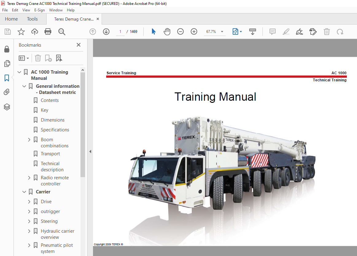

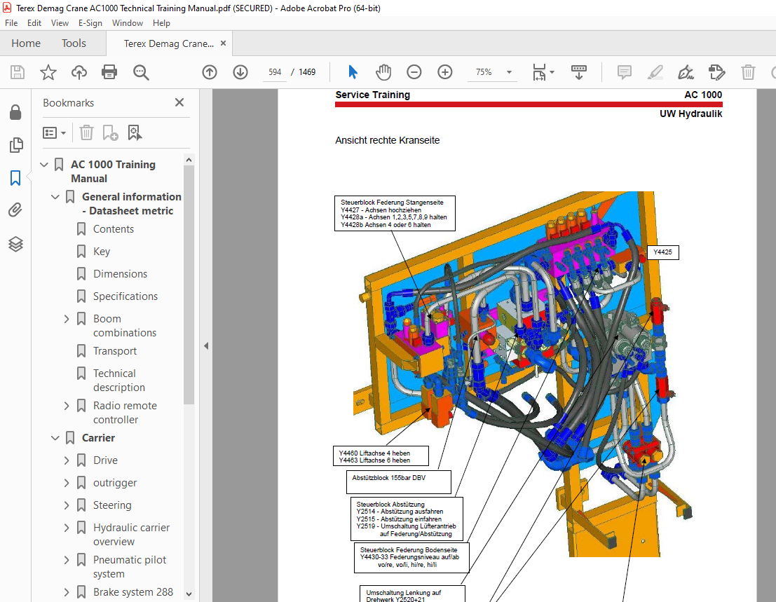
TABLE OF CONTENTS:
Terex Demag Crane AC 1000 Service Training Manual – PDF DOWNLOAD
AC 1000 Training Manual 1
General information – Datasheet metric 2
Contents 3
Key 4
Dimensions 5
Specifications 7
Boom combinations 13
HA / HA-SSL (HA50) 17
F / F-A 0°(HA50) 23
SF-SSL (30°), SF-A-SSL (30°) (HA50) 27
WIHI / WIHI-SSL (HA50) 30
WIHI-VA-SSL (60°) (HA50) 55
HA / HA-SSL (HA100) 60
F-SSL / F-A-SSL (15°/30°) 70
LF / LF-A (0°) 75
LWIHI / LWIHI-SSL (HA100) 79
Transport 16
Technical description 99
Radio remote controller 116
Components 117
Screen 118
Switsch description 119
Carrier 120
Drive 121
View engin, gear box and pump comb 122
Assemly engin and gearbox 123
Engin technical data OM 502 LA EN 3b 124
Gear box 129
Installation dimensions 130
Technical Manual ZF TC Tronic heavy duty, for transmission definition and installation inspections 132
Torque converter lock-up clutch with CAN application 132
Order n° 4245 765 101b 132
Copyright by ZF, Edition: 2009-04 133
Preface 134
List of chapters 136
Table of Contents 137
List of Changes: 4245 765 101 139
Important safety instructions 140
Technical Data and Installation Dimensions 141
1 Structure and Function 142
1 1 Structure of the TC HD 143
1 2 Structure and Function of the Torque Converter 144
1 3 Structure and Function of the Torque Converter Lock-Up Clutch 144
1 4 Structure and Function of the Shift Clutch 145
1 5 Warning Buzzer • Oil Temperature Monitoring 145
2 Mounting of Engine and Transmission 146
2 1 Mounting of Engine and Transmission 147
2 2 Mounting Points for Transport 147
3 Engine Connection 148
3 1 General information 149
3 2 Assembly Sequence 149
4 Torque Converter 150
4 1 Converter 151
4 2 Torque converter diagram 152
4 3 Oil Flow Rate With Ecofluid M in Torque Converter Operation at 90 °C 153
5 Cooling System 154
5 1 Oil/Water Heat Exchanger 155
5 2 Oil/Air Cooler 158
5 3 Installation instructions 159
5 4 Oil Fill Variants 160
6 Operation 162
6 1 Setting Off, Driving Forwards 163
6 2 Maneuvering 164
6 3 Driving in Torque Converter Mode 164
7 Maintenance 166
7 1 Oil Grades 167
7 2 Oil Fill Volume 167
7 3 Oil Change Intervals 167
7 4 Operation at Low Temperatures 167
7 5 Draining Used Oil 168
7 6 Oil Filling and Oil Level Checks 169
7 7 Filter Change 171
7 8 Oil Pressures in Torque Converter, Lock-Up Clutch 172
7 9 Tightening Torques 173
8 Peripherals 174
9 ECU 410 S 176
9 1 TC Tronic HD With ECU 41 Control Unit 177
9 2 Control unit 178
10 Electrical Power and Connection Diagrams 180
10 1 Electrical Power and Connection Diagrams 181
10 2 Electrical circuit diagram 182
10 3 Connection diagram, electrical 183
10 4 TC HD Wiring 185
10 5 Connection Diagram, Hydraulics 186
11 Diagnosis 188
11 Diagnosis, Description of Inputs and Outputs 189
12 Type Plates 190
12 1 Position of type plates 191
12 2 View of type plates (examples) 192
13 Installation Drawings 194
From drawing no 4245 600 001/1 196
From drawing no 4245 600 001/2 197
From drawing no 4245 600,002/1 198
From drawing no 4245 600,002/2 199
Distribution box 201
Gear box outputs 203
Pneumatic pilot system 204
Axle mounting 205
Axle 1 to 9 206
Cooling system EN3a and EM3b 215
Fuel system 217
Air filter system 218
EM SCR- Anlage 220
Over view 220
Suply unit 221
Pneumatic location in frame 222
Diagram SCR- system 223
SCR system EM 3b connection 224
Adblue supply unit 225
outrigger 228
Outrigger beam 229
Slewing cylinder 233
Mounting outrigger plate 234
Self- configuration of the outrigger 235
1 General 235
1 AC1000 with 12t axle load, 16″ tyres 235
1 1 Configuration of the front supports with rear auxiliary supports 0
Dismantling the auxiliary supports 0
1 3 Configuring the rear supports 0
1 4 Deconfiguring the supports 0
2 AC1000 with 100m boom with 16 5 t axle load (United Kingdom), 16″ tyres 247
2 1 Configuration of the front supports with rear supports 0
2 2 Deconfiguring the front supports with rear supports 0
3 AC1000 with 50m boom with 13 5 t axle load, 16″ tyres 251
4 Configuring the supports with the radio remote control 252
4 1 Switching on and selecting the “Supports” operating screen 0
4 2 Description of the “Supports” operating screen 0
4 3 Emergency operation 0
Steering 0
Steering overview 258
View Steering electric and hydraulic 259
Function description steering system 260
Overview steering hydraulik and electric 268
Steering electric 0
Technical datas steering computer 269
Steering hydraulic 274
Hydr – block Failop assistance steering circuit A8+9 275
Hydr – block Failsafe A7 277
Hydr – block Failop main steering circuit A8+9 279
Angle transducer steering 281
safety angle transducer 533 211 A1+A9(old) und A1,A6, A7, A9 (new) 281
angle transducer 533 250 A1+A7 old version 284
angle transducer 533 257 A6+A9 old version 285
safety angle transducer 533 450 with lever at the top pdf 286
System documentation steering 287
General system description 287
Functional description 318
Diagnostics and alarm memory 363
Alarm codes 403
Diagnostic trouble codes 444
Hydraulic carrier overview 593
Hydraulic drawing carrier 291 701 12f 595
Hydraulic tank 199 901 12d 598
Hydraulic tank 197 373 12d 599
Ass pump 197 255 12c 602
States diagram of solenoid valves 603
Pneumatic pilot system 606
Brake system 289 161 12c 608
ass pneumatic frame right 289 162 12b 611
ass pneumatik frame right side 520 270 12a 612
Brake system 288 045 12b 613
Assembly and maintenance instruction 615
Control system carrier 645
Indicator Lights in the Driver Information System 646
Electric carrier 0
Electric schematics carrier 395 104 12 V2 9 690
Elektric cabin 874
interface for programming und steering computer 896
Superstructure 0
Power unit superstructure hydraulic pumps 897
System description 898
Hoist 900
Reassignment of control lever functions 901
Hoist 0 909
Hoist 1 910
Hoist 2 911
Hoist 3 912
Reeving winch 913
Reeving winch without hoist 3 913
Reeving winch with hoist 3 917
Whirl 921
Counterweight 923
View rigging counterweight 924
Configuring the counterweight 926
Counterweight configurations page 1-9 948
Mounting counterweight frame with cyl 957
Main boom 959
Drawings 0
Tele 50m 960
Tele 50m boom assembly 393 000 12F1 960
Tele 50m boom assembly 393 000 12F2 961
Tele 50m roop reeving 4 IC 393 000 12F3 962
Tele 50m roop reeving 4 IC 393 000 12F4 963
Tele 100m 964
Tele 100m boom assembly 393 001 12F1 964
Tele 100m boom assembly 393 001 12F2 965
Tele 100m roop reeving 8 IC 393 001 12F3 966
Tele 100m roop reeving 8 IC 393 001 12F4 967
Telescopic cylinder with SVE 968
Tele sections 970
Basic case 39200012F1 970
1 IC 39210012E1 971
1 IC 39210012E2 972
2 IC 39220012E1 973
2 IC 39220012E2 974
3 IC 39230012E1 975
3 IC 39230012E2 976
4 IC 39240012E1 977
4 IC 39240012E2 978
5 IC 39250012E1 979
5 IC 39250012E2 980
6 IC 39260012E1 981
6 IC 39260012E2 982
7 IC 39270012E1 983
7 IC 39270012E2 984
8 IC 39280012E1 985
8 IC 39280012E2 986
Positioning cut off device 987
Tele cut off 5 – 6 IC 988
Position Tele 1 – 4 IC 989
Position Tele 5 – 8 IC 990
Telecylinder 393 050 12h 991
Telecylinder 393 051 12 993
SVE 393 052 12g 994
Mounting parts 4 IC 995
Emergency release pinning T1- T8 996
1 IC 56631312A 996
2 IC 56631412A1 997
3 IC 56631512A1 998
4 IC 56631612A1 999
5 IC 56631712A1 1000
6 IC 56631812A1 1001
7 IC 56631912A1 1002
8 IC 56632012A1 1003
Heavy attachment 8 IC 1004
Heavy attachment 4 IK 1005
Main boom view 1006
SVE- function prox switches 1008
Telescope example 1009
Telescope example Tele 5 from 0% zu 100% 1011
Telecope example Tele 1 from 0% to 100% 1012
Pinning positions 1013
Telemanual 1014
Configuration program for the 100m boom 1015
Replacement main boom 50m to 100m 1027
Hydraulic superstructure 1030
Hydr – drawing superstructure 291 700 12e 1031
Hydraulic function superstructure 1034
Description of the pump actuation 1037
View rotary joint 1048
Hydraulic connection rotary joint 1049
Slew gear 1050
Hydraulic drawing slew gear 1051
Control modes slew gear 1052
Pressure-less circuit, closed circuit right 1053
Open circuit left and right 1054
Electric superstructure 1194
E-drawing 565 026 12 V2 1 0 1057
X2 1194
Fail safe inductive sensor 1208
Control system superstructure 1226
Menus operating display 1227
Menus IC-1 Service 1248
Error codes 1317
Equipment 0
SSL 1371
View SSL- Cylinder 1372
SSL configuration progamm 1373
Main boom bracing 396 549 12c 1387
SSL cpl 396 572 12d 1394
SSL arm cpl left 396 573 12d 1396
Conditions SSL functions 1398
Retension matrix 100m and 50m m b 1400
View sensors and prox switches 1402
Pressure adjustment SSL 1403
Luffing fly jib 1404
Overview lenght combinations WIHI 1405
WIHI 50m HA 24m- 126m 1405
LWIHI an 100m HA 24m- 84m 1406
SF 50m HA 8m- 74m and F 14m- 74m 1407
LF – 100m HA and F – 100m HA 1408
Two hook block mode 24m-84m 1409
Offsetable luffing fly jib on 50m boom 1410
Combination luffing fly jib 1412
Dimensions and weights jib parts 1411
Assembling WIHI 50m HA 1412
Rigging =< 72m 1413
WIHI low and high position 1414
Erecting WIHI => 78m 1415
Removel or change WIHI lenght =< 72m 1416
Lowering WIHI => 78m 1417
Rigging WIHI with offset 40° 1418
Assembling LWIHI 100m HA 1419
Rigging LWIHI 1420
LWIHI low and high position 1421
LWIHI removal or change jib lenght 1422
2-Hook block mode 1423
Offset on Pos 6 to Pos 4 1424
Offset F44m with 0°, 8°, 20° and 40° 1425
Option VA- Adapter assembling 1426
Option VA- Adapter rigging until 72m 1427
Option VA- Adapter to telescope 1428
Option VA- Adapter rigging WIHI => 78m 1429
Reeving mode on pos 9 HiA- head piece 6m > 78m 1430
Reeving mode on pos 7 HiA- head piece 3m =< 72m 1431
Intermediate bracing 1432
Fix bridle with rocker arm 1433
Configuring and operating the fixed bridle 1434
Configuring and operating the luffing fly jib 1449
Assembling proximity switches 1467
More products