$44
Terex Demag Crane CC2800-1 600T Mounting Manual – PDF DOWNLOAD
Terex Demag Crane CC2800-1 600T Mounting Manual – PDF DOWNLOAD
FILE DETAILS:
Terex Demag Crane CC2800-1 600T Mounting Manual – PDF DOWNLOAD
Language : English
Pages : 938
Downloadable : Yes
File Type : PDF
IMAGES PREVIEW OF THE MANUAL:
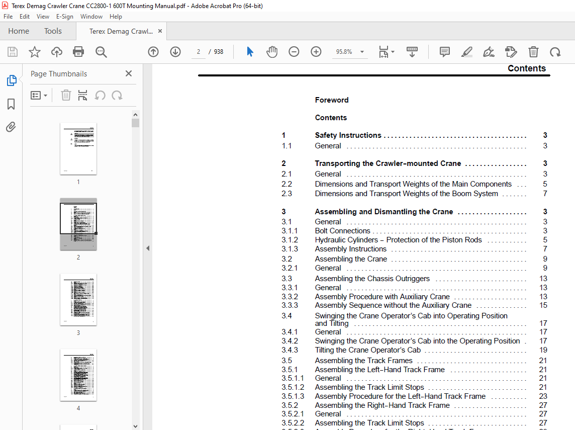

TABLE OF CONTENTS:
Terex Demag Crane CC2800-1 600T Mounting Manual – PDF DOWNLOAD
Foreword
Contents
1 Safety Instructions 3
1 1 General 3
2 Transporting the Crawler–mounted Crane 3
2 1 General 3
2 2 Dimensions and Transport Weights of the Main Components 5
2 3 Dimensions and Transport Weights of the Boom System 7
3 Assembling and Dismantling the Crane 3
3 1 General 3
3 1 1 Bolt Connections 3
3 1 2 Hydraulic Cylinders — Protection of the Piston Rods 5
3 1 3 Assembly Instructions 7
3 2 Assembling the Crane 9
3 2 1 General 9
3 3 Assembling the Chassis Outriggers 13
3 3 1 General 13
3 3 2 Assembly Procedure with Auxiliary Crane 13
3 3 3 Assembly Sequence without the Auxiliary Crane 15
3 4 Swinging the Crane Operator’s Cab into Operating Position
and Tilting 17
3 4 1 General 17
3 4 2 Swinging the Crane Operator’s Cab into the Operating Position 17
3 4 3 Tilting the Crane Operator’s Cab 19
3 5 Assembling the Track Frames 21
3 5 1 Assembling the Left–Hand Track Frame 21
3 5 1 1 General 21
3 5 1 2 Assembling the Track Limit Stops 21
3 5 1 3 Assembly Procedure for the Left–Hand Track Frame 23
3 5 2 Assembling the Right–Hand Track Frame 27
3 5 2 1 General 27
3 5 2 2 Assembling the Track Limit Stops 27
3 5 2 3 Assembly Procedure for the Right–Hand Track Frame 29
3 5 3 Connecting the Hydraulic Lines 35
3 6 Assembling the Central Ballast on the Chassis 37
3 6 1 General 37
3 6 2 Assembly Procedure 37
3 7 Assembling the Counterweight 39
3 7 1 General 39
3 7 2 Mounting Sequence 41
3 8 Raising the A–Frame and Placing the A–Frame in the Assembly
Position 43
Contents
062–3003–200 2
3 9 Dismantling the Crane 45
3 9 1 General 45
3 10 Folding the A–Frame into the Transport Position 49
3 11 Dismantling the Counterweight 51
3 12 Dismantling the Central Ballast on the Chassis 53
3 13 Dismantling the Track Frame 55
3 13 1 Dismantling the Hydraulic Lines 55
3 13 2 Assembling the Track Limit Stops 55
3 13 3 Supporting the Crane on Outriggers 57
3 13 4 Dismantling the Right–Hand Track Frame 59
3 13 4 1 General 59
3 13 4 2 Dismantling the Right–Hand Track Frame 61
3 13 5 Dismantling the Left–Hand Track Frame 65
3 13 5 1 General 65
3 13 6 Dismantling the Left–Hand Track Frame 67
3 14 Tilting and Swinging the Cab into the Transport Position 71
3 14 1 General 71
3 14 2 Tilting the Crane Operator’s Cab 71
3 14 3 Swinging the Crane Operator’s Cab into the Transport Position 73
3 15 Dismantling the Chassis Outriggers 75
3 15 1 General 75
3 15 2 Dismantling Procedure with the Auxiliary Crane 75
3 15 3 Dismantling Procedure without the Auxiliary Crane 77
4 Assembling the Main Boom 3
4 1 General 3
4 2 Assembling and Fitting the Main Boom SH 5
4 2 1 Assembling Main Boom Combinations SH 7
4 2 2 Fitting Main Boom Combination SH 29
4 2 3 Assembling the Main Boom Stay Bars with the Combination SH 39
4 2 4 Fitting the Runner on the Connecting Head 41
4 2 5 Dismantling the Runner 45
4 3 Assembling and Fitting the Main Boom SH/LH,
Heavy Basic Length of the Main Boom 58 5 m 47
4 3 1 Assembling the Main Boom Combinations SH/LH,
Heavy Basic Length of the Main Boom 58 5 m 49
4 3 2 Fitting the Main Boom Combinations SH/LH 71
4 3 3 Assembling the Main Boom Stay Bars for the
Combination SH/LH 79
4 3 4 Fitting the Runner on the Main Boom SH/LH 81
4 3 5 Dismantling the Runner 85
4 3 6 Assembling the Auxiliary Bracing (Bracing Chains) for the
Combination SH/LH 87
4 3 6 1 Assembling the Auxiliary Bracing (Bracing Chains) for the
Combination SH/LH — Jib Length 90 m and 96 m 87
4 3 6 2 Assembling the Auxiliary Bracing (Bracing Chains) for the
Combination SH/LH — Jib Length 102 m 89
Contents
062–3003–200 3
5 Assembling the Main Boom and Fly Jib 3
5 1 General 3
5 2 Assembling and Fitting Fly Jib Combination SW 5
5 2 1 Assembling Main Boom Combination SH for Variant SW 7
5 2 2 Assembling Fly Jib Combinations for Variant SW 21
5 2 3 Fitting Main Boom and Fly Jib SW 43
5 2 4 Fitting the Runner 73
5 2 5 Assembling Stay Bars HA and HI and Bracing Rods WU for the
Combination SW 81
5 2 6 Assembling the additional bracing (bracing chains) for the
combination SW 83
6 Assembling and Dismantling the Superlift 3
6 1 General 3
6 1 1 Bolt Connections 3
6 1 2 Hydraulic Cylinders — Protecting the Piston Rods 7
6 1 3 Assembly Instructions 9
6 2 Assembling and Fitting the Superlift Mast 11
6 2 1 General 11
6 3 Assembling the Superlift Mast (SL Mast) 17
6 3 1 Superlift mast with counterweight supporting frame
(SL counterweight radius 11 m, mast radius 11 5 m) 17
6 3 1 1 Counterweight Frame and Connecting Ropes
(SL Counterweight Radius 11 m) 19
6 3 2 Superlift mast with counterweight supporting frame
(SL counterweight radius 13 m, mast radius 13 5 m) 21
6 3 2 1 Counterweight frame and connecting ropes
(SL Counterweight Radius 13 m) 23
6 3 3 Superlift mast with counterweight supporting frame
(SL counterweight radius 15 m, mast radius 15 5 m) 25
6 3 3 1 Counterweight Frame and Connecting Ropes
(SL Counterweight Radius 15 m) 27
6 3 4 Fitting the Superlift mast 29
6 3 5 Assembling the Luffing Lifting Beam 35
6 3 6 Fitting the Superlift Counterweight 37
6 4 Dismantling the Superlift 43
6 4 1 General 43
6 4 2 Dismantling the Superlift Counterweight 45
6 4 3 Dismantling the Luffing Lifting Beam 51
6 4 4 Dismantling the Superlift Mast 53
6 4 4 1 Dismantling the Hydraulic Lines for Luffing Gear 2 53
6 4 4 2 Setting Down the Superlift Mast 53
7 Assembling the Main Boom with Superlift 3
7 1 General 3
7 2 Assembling and Fitting the SSL Superlift Combination 7
7 2 1 Assembling the SSL Main Boom Combinations 9
7 2 2 Fitting the SSL Main Boom Combination 35
7 2 2 1 Fitting Procedure on the Ground 35
7 2 2 2 Fitting Procedure “Assembly in the Air”: 41
7 2 3 Assembling the HA Stay Bars on the SSL Combination 51
Contents
062–3003–200 4
7 2 4 Fitting the Runner on the Connecting Head 53
7 2 5 Dismantling the Runner 57
7 3 Assembling and Fitting the SSL/LSL Main Boom 59
7 3 1 Assembling the SSL/LSL Main Boom Combinations 61
7 3 2 Fitting the SSL/LSL Main Boom Combination 93
7 3 3 Assembling the HA Stay Bars for Combination SSL/LSL 101
7 3 4 Fitting the Runner on the Top Piece 103
7 3 5 Dismantling the Runner 107
7 3 6 Assembly of the additional suspension (suspension chains) for the
combination SSL/LSL 109
8 Assembling the Main Boom and Fly Jib with Superlift 3
8 1 General 3
8 2 Assembling and Fitting the Boom Combination SWSL 5
8 2 1 Assembling the Main Boom Combination for the Variant SWSL 7
8 2 2 Assembling the Fly Jib Combination for the Variant SWSL 59
8 2 3 Fitting the Main Boom and Fly Jib Combination SWSL 81
8 2 4 Fitting the Runner 111
8 2 5 Assembling the Stay Bars HA and HI and the Bracing Rods WU
for the Combination SWSL 121
8 2 6 Assembling the additional suspension (suspension chains) for the
combination SWSL 123
9 Reeving the Ropes 3
9 1 General 3
9 2 Reeving the Derricking Ropes 5
9 2 1 General 5
9 2 2 Table for Reeving the Derricking Ropes 5
9 3 Reeving the Luffing Ropes 7
9 3 1 Reeving the Luffing Rope W1 7
9 3 1 1 General 7
9 3 1 2 Table for Reeving the Luffing Rope W1 7
9 3 2 Reeving the Luffing Rope W2 9
9 3 2 1 General 9
9 3 2 2 Table for reeving the luffing rope W2 9
9 4 Reeving the Hoist Ropes 11
9 4 1 Reeving the Hoist Ropes — Combination SH and SSL 11
9 4 2 Reeving the Hoist Ropes — Combination SH/LH and SSL/LSL 23
9 4 3 Reeving the Hoist Rope — Combination SW and SWSL 37
9 4 4 Reeving the Hoist Ropes — Combination LF 51
9 4 4 1 Combination LF — Main boom SH 53
9 4 4 2 Combination LF — main boom SH/LH 61
9 4 5 Reeving the Hoist Ropes — Combination LFSL 69
9 4 5 1 Combination LFSL — Main boom SSL 71
9 4 5 2 Combination LFSL — main boom SSL/LSL 79
10 —
11 —
12 —
Contents
062–3003–200 5
13 Hydraulic Power Pack with Pin Locking Cylinder 3
13 1 General 3
13 2 Starting the Hydraulic Power Pack 7
13 3 Actuation of the Pin Locking Cylinder 7
13 4 Setting down the Hydraulic Power Pack 7
14 —
15 Assembling the Main Boom and Fly Jib LF 3
15 1 General 3
15 2 Assembling and Fitting the Fly Jib Combination LF
(Main boom SH) 5
15 2 1 Assembling the Main Boom Combination SH for the Variant LF 7
15 2 2 Assembling the Fly Jib Combination for the Variant LF
(Main Boom SH) 29
15 2 3 Fitting the Main Boom and Fly Jib Combination SH + LF 35
15 3 Assembling and fitting the fly jib combination LF (main boom SH/LH,
heavy basic length SGL of the main boom 58 5 m) 57
15 3 1 Assembling the main boom combinations SH/LH for the variant LF (SGL
58 5 m) 59
15 3 2 Assembling the Fly Jib Combination for the Variant LF
(Main Boom SH/LH) 81
15 3 3 Fitting the main boom and fly jib combinations
SH/LH + LF 93
15 3 4 Assembling the Auxiliary Bracing (Bracing Chains) for the
Combination SH/LH 115
15 3 4 1 Assembling the Auxiliary Bracing (Bracing Chains) for the
Combination SH/LH — Jib Length 90 m and 96 m 115
15 3 4 2 Assembling the Auxiliary Bracing (Bracing Chains) for the
Combination SH/LH — Jib Length 102 m 117
16 —
17 —
18 Assembling the Main Boom and Fly Jib LF with Superlift 3
18 1 General 3
18 2 Assembling and Fitting the Fly Jib Combination LF
(Main Boom SSL) 7
18 2 1 Assembling the Main Boom Combination SSL for the Variant LF 9
18 2 2 Assembling the fly jib combinations LF
(main boom SSL) 27
18 2 3 Fitting the Main Boom and Fly Jib Combination SSL + LF 33
18 3 Assembling and fitting the fly jib combination LF
(main boom SSL/LSL) 57
18 3 1 Assembling the Main Boom Combination SSL/LSL for the
Variant LF 59
18 3 2 Assembling the fly jib combinations LF
(main boom SSL/LSL) 91
18 3 3 Fitting the main boom and fly jib combinations SSL/LSL + LF 103
18 3 4 Assembly of the additional suspension (suspension chains) for the
combination SSL / LSL 127

