$39
Terex TX 51-19MD Rough Terrain Forklift Shop Manual – PDF DOWNLOAD
Terex TX 51-19MD Rough Terrain Forklift Shop Manual – PDF DOWNLOAD
FILE DETAILS:
Terex TX 51-19MD Rough Terrain Forklift Shop Manual – PDF DOWNLOAD
Language : English
Pages : 494
Downloadable : Yes
File Type : PDF
Light Capability Rough Terrain Forklift
(LRTF)
TX 51-19MD
SHOP MANUAL
Document 57.4400.9204 – Rev. 0 01/2011
PCN 500 091352 00
TM 09135C-OI
CONTRACT NO. M67854-10-D-5074
IMAGES PREVIEW OF THE MANUAL:
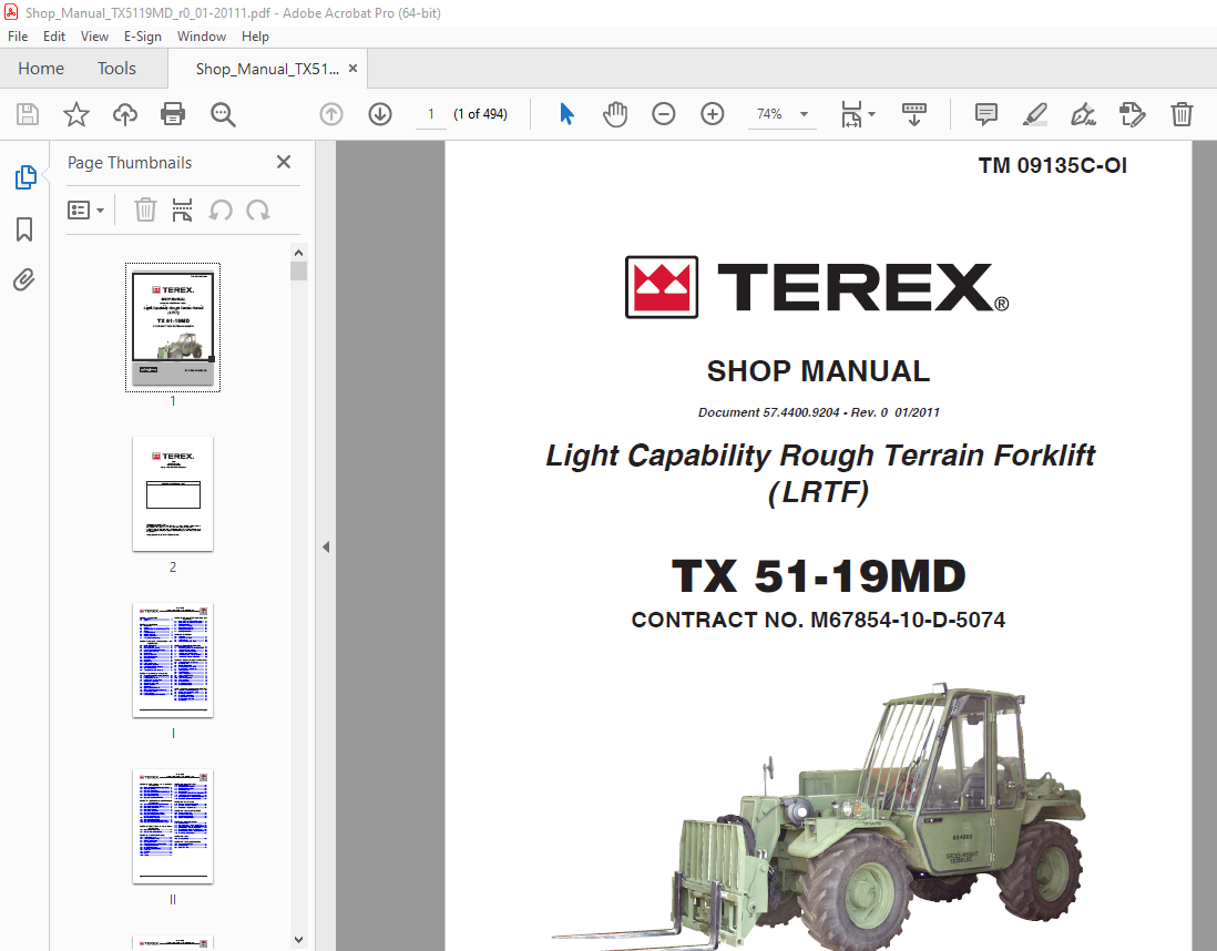
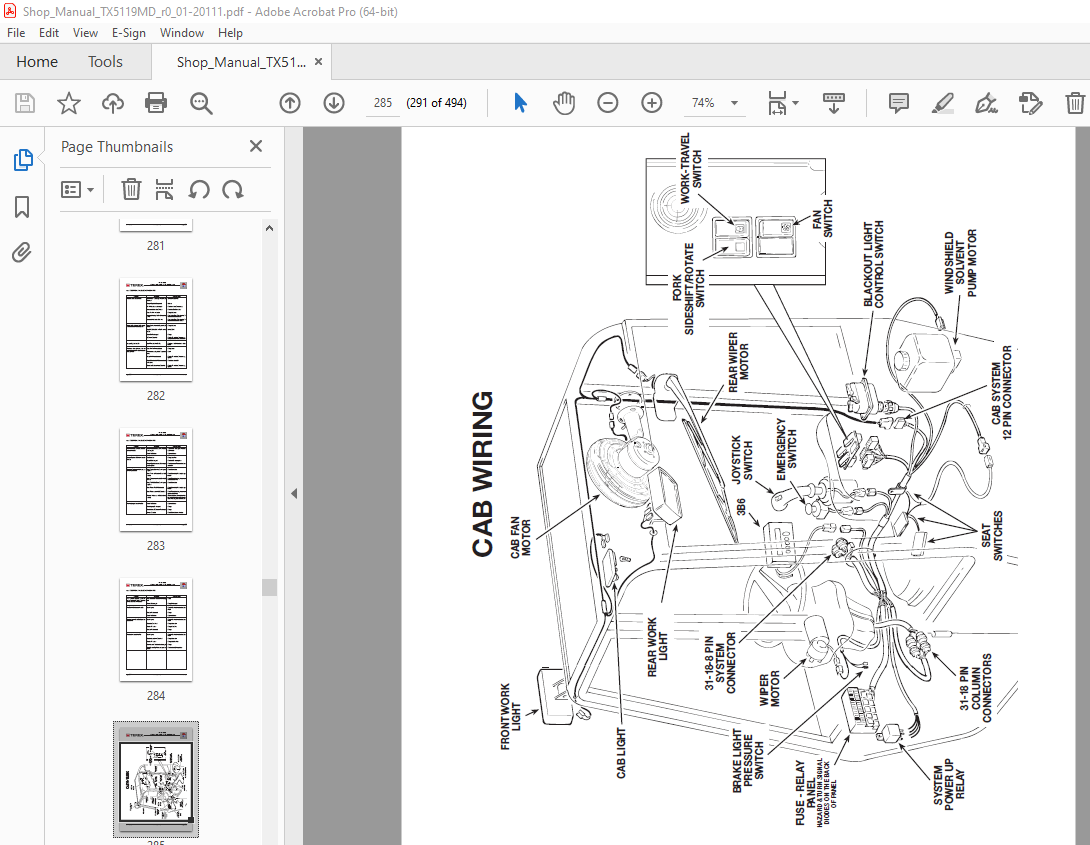
TABLE OF CONTENTS:
Terex TX 51-19MD Rough Terrain Forklift Shop Manual – PDF DOWNLOAD
Section 1 – Introduction
1 0 Introduction 3
1 1 Symbols 4
Section 2 – Safety Rules
2 0 Safety Rules 7
2 1 General 7
2 2 Operators Maintenance Staff Responsibilities 7
2 3 Clothing 7
2 4 Personal Equipment 8
2 5 Safety Precautions 8
2 6 Getting Ready to Work 8
2 7 During Work or Maintenance 8
Section 3 – General Information and
Specification
3 0 Machine References 13
3 1 Machine Position 13
3 2 Labels and Warning Decals 14
3 3 Explanation of the Different Symbols 19
3 4 Machine Model and Type 20
3 5 Manufacturer 20
3 6 Machine Identification 20
3 7 Chassis Serial Number 21
3 8 Identification Plates 21
3 9 Allowed Use 21
3 10 Improper Use 21
3 11 Applicable Standards 22
3 12 List of Main Components 22
3 13 Description of Main Components 23
3 14 Optional Accessories 23
3 15 Technical Data and Performance 24
Section 4 – Controls and Instruments
4 0 Preoparation, Inspection and Adjustments 29
4 1 Adjusting the Seat 29
4 2 Fastening the Seat Belts 30
4 3 Adjusting the Rear View Mirrors 30
4 4 Controls and Operations 32
4 5 Controls and Instruments 33
4 6 Control Description 34
4 7 Control Lever 43
4 8 Operating the Control Lever 44
4 9 Tilting the Forks Forward and Rearward 45
4 10 Side Shifting the Forks 46
4 11 Rotating the Forks 47
4 12 Quick-Coupling the Fork Attachment 48
Section 5 – Pre-operation Inspection and
Adjustment
5 0 Pre-operation Inspection and Adjustment 51
5 1 Pre-operation Inspection and Check List 51
5 2 Starting the Engine 51
5 3 Jump-Starting the Engine 52
5 4 Battery Disconnect Switch 52
5 5 Stopping / Parking Machine 53
5 6 Refueling the Machine 53
Section 6 – Lubrication
6 0 Lubrication 57
6 1 Lubricant Specification 57
6 2 Lubricant Chart 58
6 3 Lube and Fluid Capacity Chart 59
Section 7 – Preventive Maintenance
7 0 Preventive Maintenance 63
7 1 Using the Suggested Schedule Check Sheet 63
7 2 50 Hours or Weekly Services 65
7 3 250 Hours or Monthly Services 66
7 4 500 Hours or Quarterly Services 67
7 5 1000 Hours or Semi-Annually Services 68
7 6 3000 Hours or Three Years Services 69
Section 8 – 50 Hours or Weekly Maintenance
8 0 50 Hours Or Weekly Maintenance 73
8 1 Check Engine Oil 73
8 2 Drain Engine Fuel Filter 73
8 3 Check Hydraulic Reservoir Oil 74
8 4 Check Brake Oil Reservoir Level 74
8 5 Lube Boom Pads 74
8 6 Lube Drive Shaft 75
8 7 Lube Axle King Pins 75
8 8 Lube Axle Rear Pivot Pin 75
8 9 Lube Cylinders 75
8 10 Lube Fork Attachments 76
8 11 Lube Boom Pivot 76
8 12 Check Tire Inflation 76
8 13 Check Tire Wheel Nuts 76
8 14 Check Drive Shaft Bolts 77
Section 9 – 250 Hours or Monthly Maintenance
9 0 250 Hours Or Monthly Maintenance 81
9 1 Engine and Hydraulic Oil Sampling 81
9 2 Check Engine Air Filter 81
9 3 Check Engine Drive Belts 82
9 4 Check Axle Wheel Ends Oil 82
9 5 Check Axle Differential Oil 83
9 6 Check Battery 83
Page II TX51-19MD-1-SM 57 4400 9204
TX 51-19MD
Light Capability Rough Terrain Forklift (LRTF)
Section 10 – 500 Hours or Quarterly
Maintenance
10 0 500 Hours or Quarterly Maintenance Checks 87
10 1 Change Engine Oil 87
10 2 Change Engine Oil Filter 88
10 3 Change Engine Air Filter (external cartridge) 89
10 4 Change Engine Fuel Filter 90
10 5 Check Engine Glow Plugs 91
10 6 Change Hydraulic Reservoir Filter 91
Section 11 – 1000 Hours or Semi-Annually
Maintenance
11 0 1000 Hours or Semi-Annually Maintenance 95
11 1 Check Engine Valve Tip Clearance 95
11 2 Check Electrical Alternator 95
11 3 Check Electrical Starter 95
11 4 Check Electrical System 96
11 5 Check Hydraulic Hoses and Fitting 96
11 6 Change Hydraulic Reservoir Oil Filter,
Cleaning Hydraulic Magnet 96
11 7 Change Axle Wheel End Oil 97
11 8 Change Axle Differential Oil 97
11 9 Check Accumulator Pre-charge Pressure 98
11 10 Change Engine Air Filter (internal cartridge) 98
Section 12 – 3000 Hours or Three Years
Maintenance
12 0 3000 Hours or Three Years 101
12 1 Check Atomisers (Fuel Injector) 101
Section 13 – Routine Maintenance
13 0 Routine Maintenance 105
13 1 Replacing the Attachments 105
13 2 Slider Pads Adjustment 106
13 3 Changing Slider Pads 106
13 4 Attachment Plate Removal / Installation 108
13 5 Parking Brake Adjustment 109
13 6 Bleeding Brake System 111
13 7 Proximity Switch Adjustment 111
13 8 Drive Shaft 111
13 9 Fuel Tank 113
13 10 Oil Tank 114
13 11 Radiator 115
Section 14 – Hydraulic Boom
14 0 Boom Introduction 121
14 1 Boom Removal / Installation 121
14 2 Tilt Cylinder Replacement 124
14 3 Boom Disassembly 125
14 4 Boom Assembly 126
14 5 Compensation Cylinder Removal / Installation 127
14 6 Locking Cylinder Removal / Installation 128
14 7 Boom Hoist Cylinder – Removal / Installation 130
14 8 Extend Cylinder Removal / Installation 133
Section 15 – Carraro Axles
15 0 Front Alxe – Removel / Installation 137
15 1 Rear Axle – Removel / Installation 141
15 2 Carraro Axles – Repair manual 143
Section 16 – Troubleshooting Guide
16 0 Troubleshooting Guide 275
16 1 General Troubleshooting 275
16 2 Hydraulic Troubleshooting 276
16 3 Electrical Troubleshooting 281
Section 17 – Hydraulic System
17 0 Hydraulic System 297
17 1 Hyd Drive Pump – Removal / Installation 297
17 2 Cylinder Holding Valve – Removal / Installation 298
17 3 Hydraulic Motor – Removel / Installation 298
17 4 Rexroth Pump (A4vG) – Repair istructions 299
17 5 Rexroth Motor (A6Vm107) – Repair istructions 341
17 6 Rexroth Operating Istructions 381
Section 18 – Engine
18 0 Operating Manual 399
Section 19 – Tables and Enclosures
19 0 Torque Wrench Settings 453
19 1 Pressure Setting 455
19 2 Special Tool List 457
57 4400 9204 TX51-19MD-1-SM Page III
TX 51-19MD
Light Capability Rough Terrain Forklift (LRTF)
Section 20 – 3B6 Technologies LMI System
20 0 3B6 Load Moment Indicator Manual 465
20 1 System lay-out and connections 466
20 2 Components location on the machine 467
20 3 Infolift main unit: Characteristics 468
20 4 Infolift main unit: Dimensions 469
20 5 Load cell amplifier: Dimensions,
characteristics, cable 470
20 6 Control panel description 471
20 7 Display information: Working messages 472
– Power-on sequence
– Safe working condiotion
– Warning condition
– Shut-off condition
– Setting mode
– Shut-off over ride
20 8 Display information: Diagnostics messages 475
– A01 crc error
– A02 cellalarm
– A03 cellallarm
20 9 Standard operating mode 476
– Normal / safe working load
– Pre-warning working load
– Overload working load
– By-pass pushbutton
20 10 Accuracy verification 480
– Pushbuttons functions
– Procedure
20 11 Accuracy verification mode 482
– First time accuracy verification
– Re-accuracy verification
– Load cell reading
– Empty accuracy verification
– Laden accuracy verification
– Cut-off percentage
– Empty moment
– Laden moment
– Filter
20 12 How to set a numeric value 485
20 13 How to set the password 486
20 14 External wiring 487
20 15 Spare parts list 488
20 16 Warnings 488
More products