$25.95
UTILEV UT80-100P DSL 8T-10T Internal Combustion Forklift Truck Service Manual PDF
UTILEV UT80-100P DSL 8T-10T Internal Combustion Counterbalanced Forklift Truck Service Manual – PDF DOWNLOAD
FILE DETAILS:
UTILEV UT80-100P DSL 8T-10T Internal Combustion Counterbalanced Forklift Truck Service Manual – PDF DOWNLOAD
Language : English
Pages : 98
Downloadable : Yes
File Type : PDF
IMAGES PREVIEW OF THE MANUAL:
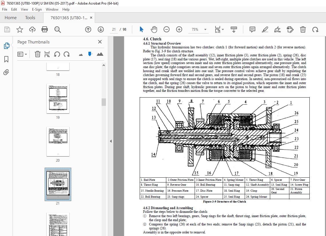
TABLE OF CONTENTS:
UTILEV UT80-100P DSL 8T-10T Internal Combustion Counterbalanced Forklift Truck Service Manual – PDF DOWNLOAD
I Power System 1
1 Engine 2
2 Intake System 5
3 Exhaust System 7
4 Cooling System 7
II Universal Joint 8
III Hydraulic Transmission Gearbox 9
1 Overview 9
2 Main Technical Parameters 10
3 Principles of Operation 11
4 Structural Overview 13
5 Precautions for Fitting and Use 18
6 Troubleshooting 18
IV Drive Axle Assembly 19
1 Drive Shaft Basic Structure and Working Principles 19
2 Periodic Technical Services 21
3 Lubricating the Drive Shaft 21
4 Lifting
the Drive Axle 21
5 Driven Spiral Bevel Gear Meshing Condition and Adjustment Method 22
6 Troubleshooting 23
7 Removal and Fitting 24
V Steering System 31
1 Hydraulic Steering Mechanism 31
2 Steering Axle 33
VI Brake System 36
1 Specifications 36
2 Troubleshooting 37
3 Pedal Height and Free Travel 38
4 Maste
r Cylinder and Accumulator 39
5 Parking brake 41
6 Service Brake 44
7 Troubleshooting Hydraulic Brake Issues 47
8 Bleeding Air from the Hydraulic Brake System 47
VII Hydraulic System 48
1 Oil Pump 48
2 Control Valve 50
3 Rotating Pipe Filter 53
4 Flow Regulator Valve 54
5 Lift Cylinder 55
6 Tilt Cylinder 55
7 Bleeding Air from the Hydraulic System 56
8 Fault Diagnosis and Troubleshooting the Hydraulic System 56
9 Schematic Diagram of Hydraulic System 57VIII Lifting System 58
1 Assembly and Commissioning Data 59
2 Fault Diagnosis and Troubleshooting 60
3 Overview 61
4 Mast Removal, Fitting and Adjustment 62
5 Removal and Fitting of Lift Cylinders 64
6 Removal and Fitting of Tilt Cylinder 65
7 Commissioning After Installation 65
IX Removal and Fitting of the Overhead Guard 66
X Electrical System 68
1 Control Module 68
2 Key (start) Switch71
3 Instrument Cluster Assembly
3 Instrument Cluster Assembly 7272
4 Combination Switch Assembly
4 Combination Switch Assembly 7474
5 Gear Lever
5 Gear Lever 7474
6 Lamp Combination Switch
6 Lamp Combination Switch 7575
7 Starter and Alternator Troubleshooting
7 Starter and Alternator Troubleshooting 7777
8 Engine Fault Inspection
8 Engine Fault Inspection 7878
9 Circuit Diagram
9 Circuit Diagram 9393
More products