$23
Volvo Penta 31, 32, 41, 42, 43, 44, 300 Series Electrical System wiring Diagrams Workshop Manual PDF
Volvo Penta 31, 32, 41, 42, 43, 44, 300 Series Electrical System wiring Diagrams Workshop Manual_336168663 – PDF DOWNLOAD
FILE DETAILS:
Volvo Penta 31, 32, 41, 42, 43, 44, 300 Series Electrical System wiring Diagrams Workshop Manual_336168663 – PDF DOWNLOAD
Language : English
Pages : 84
Downloadable : Yes
File Type : PDF
Size: 24.8 MB
IMAGES PREVIEW OF THE MANUAL:


DESCRIPTION:
Volvo Penta 31, 32, 41, 42, 43, 44, 300 Series Electrical System wiring Diagrams Workshop Manual_336168663 – PDF DOWNLOAD
General information :About the workshop manual :
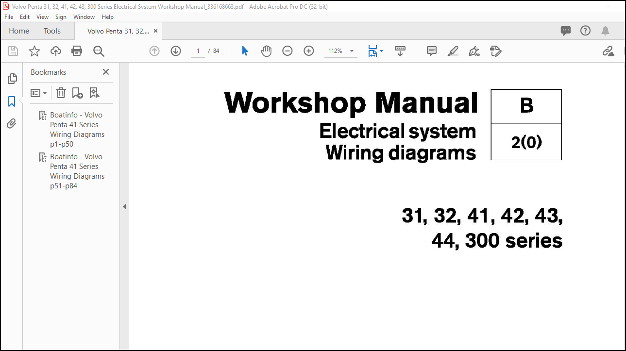
This workshop manual contains wiring diagrams, descriptions and repair instructions for the electrical system used in the standard engines in the 31, 32, 41, 42, 43, 44 and 300 series. However, electrical components in the EDC system for engines in the 44 and 300 series are covered in a separate workshop manual, see “EDC I fuel system”.
- This Workshop Manual has been developed primarily for Volvo Penta service workshops and qualified personnel. Persons using this book are assumed to have a grounding in marine drive systems and be able to carry out related mechanical and electrical work.
- Volvo Penta is continuously developing their products. We therefore reserve the right to make changes. All the information contained in this book is based on product data available at the time of going to print. Any essential changes or modifications introduced into production or updated or revised service methods introduced after the date of publication will be provided in the form of Service Bulletins.
Replacement parts:
Replacement parts for electrical and fuel systems are subject to statutory requirements (US Coast Guard Safety Regulations for example). Volvo Penta Genuine parts meet these requirements. Any type of damage which results from the use of non-original Volvo Penta replacement parts for the product will not be covered under any warranty provided by Volvo Penta.
TABLE OF CONTENTS:
Volvo Penta 31, 32, 41, 42, 43, 44, 300 Series Electrical System wiring Diagrams Workshop Manual_336168663 – PDF DOWNLOAD
Safety infonnation .. . ……… ………. ……… ……… ……. 2
General information . . . . .. . . . . . . . .. . . . . . . . . .. . . . . . . . .. . . . . . . . .. . . 5
Special tools .. . ……… ……… ………. ……… ……… ……. 6
Other special equipment . ……… ………. …….. ……… 6
Design and function ……… ……… ………. ……… ……. 7
General……………………………………………………… 7
Generator…………………………………………………… B
Starter motor . . . . . . . . . . . . . . . . . . . . . . . . . . . . . . . . . . . . . . . . . . . . . . . . . . . . . . B
Electrical connection box ……. ……….. ………. ……. 9
Fuses and circuit breakers …………………………… 10
Monitors . . . .. . . . . . . . .. . . . . . . . .. . . . . . . . .. . . . . . . . . .. . . . . . . . .. . . . . . . . .. . . 10
Glow plugs…………………………………………………. 10
Sensors …………………………………………………….. 11
Solenoid valve .. . …….. …….. ……… …….. …….. …….. 11
Engine speed relay .. …….. ……. …… …….. ……. ……. 12
Charging system ………………………………………….. 14
General ……………………………………………………… 14
Technical data .. . …….. …….. ……… …….. …….. …….. 14
Faultfinding … . ……. …….. …….. …….. ……. …….. ……. 15
Wiring diagrams, engine ………………………………. 20
31/411-pole ……………………………………………….. 20
KAD32, KA(M)D42/43 1-pole ………………………… 22
TAMD42AWJ, BWJ, WJ 1.5-pole ………………….. 24
31/41 1.5-pole 12 V ……………………………………… 26
31/41 1.5-pole 24 V ……………………………………… 28
441300 ……………………………………………………….. 30
Wiring diagrams, instrument panel ……………….. 34
Instrument panel, main station ……………………… 34
Instrument panel, fly bridge ………………………….. 36
Instrument kit, main station ………………………….. 3B
Instrument kit, fly bridge ………………………………. 40
Clutch control panel, water jet ………………………. 42
Diode cable, 1.5-pole electrical system ………….. 44
EDC control system … . ……… ……… ……… ……… ….. 46
Control panels…………………………………………….. 46
Color-codes for EDC cables …………………………. 58
Electronic control ………………………………………… 61
Mechanical control………………………………………. 64
Wiring diagrams, Power trim ………………………… 66
SX, DP-S …………………………………………………… 67
290, SP, DP ………………………………………………. 72
DPX ……………………………………………………….. … 75
Corrosion protection system ……. ………. ……… …. 76
Active corrosion protection system ……………….. 76


