$32
Volvo Penta 4.3GXi- 8.1GXil EFI Repair Workshop Manual_118130011 – PDF DOWNLOAD
Volvo Penta 4.3GXi- 8.1GXil EFI Repair Workshop Manual_118130011 – PDF DOWNLOAD
FILE DETAILS:
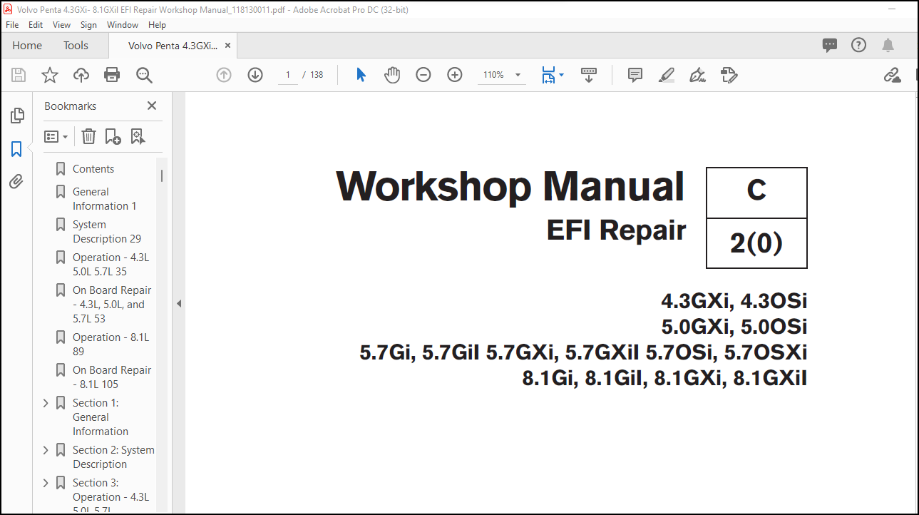
Volvo Penta 4.3GXi, 4.3OSi 5.0GXi, 5.0OSi 5.7Gi, 5.7GiI 5.7GXi, 5.7GXiI 5.7OSi, 5.7OSXi 8.1Gi, 8.1GiI, 8.1GXi, 8.1GXiI EFI Repair Workshop Manual_118130011 – PDF DOWNLOAD
Language : English
Pages : 138
Downloadable : Yes
File Type : PDF
Size: 5.22 MB
IMAGES PREVIEW OF THE MANUAL:
DESCRIPTION:
Volvo Penta 4.3GXi, 4.3OSi 5.0GXi, 5.0OSi 5.7Gi, 5.7GiI 5.7GXi, 5.7GXiI 5.7OSi, 5.7OSXi 8.1Gi, 8.1GiI, 8.1GXi, 8.1GXiI EFI Repair Workshop Manual_118130011 – PDF DOWNLOAD
4.3GXi, 4.3OSi
5.0GXi, 5.0OSi
5.7Gi, 5.7GiI 5.7GXi, 5.7GXiI 5.7OSi, 5.7OSXi
8.1Gi, 8.1GiI, 8.1GXi, 8.1GXiI
General Information
Good Service Practice
Service required for the engine and sterndrive is generally one of three
kinds:
• Normal care and maintenance – which includes putting a new
engine and stern drive into operation, storing, lubrication, and
care under special operating conditions such as salt water and
cold weather.
• Operating malfunctions – due to improper engine or drive
mounting, propeller condition or size, boat condition, or the malfunction
of some part of the engine. This includes engine servicing
procedures to keep the engine in prime operating
condition.
• Complete disassembly and overhaul – such as major service
or rebuilding a unit.
It is important to determine before disassembly just what the trouble is
and how to correct it quickly, with minimum expense to the owner.
When repairing an assembly, the most reliable way to ensure a good
job is to do a complete overhaul on that assembly, rather than just to
replace the bad part. Wear not readily apparent on other parts could
cause malfunction soon after the repair job. Repair kits and seal kits
contain all the parts needed to ensure a complete repair, to eliminate
guesswork, and to save time.
Repair time can also be minimized by the use of special tools. Volvo
Penta special tools are designed to perform service procedures unique
to the product that cannot be completed using tools from other
sources. They also speed repair work to help achieve service flat rate
times. In some cases, the use of substitute tools can damage the part.
Preparation for Service :
Proper preparation is extremely helpful for efficient service work. A
clean work area at the start of each job will minimize tools and parts
becoming misplaced. Clean an engine that is excessively dirty before
work starts. Cleaning will occasionally uncover trouble sources. Obtain
tools, instruments and parts needed for the job before work is started.
Interrupting a job to locate special tools or repair kits is a needless
delay.
TABLE OF CONTENTS:
Volvo Penta 4.3GXi, 4.3OSi 5.0GXi, 5.0OSi 5.7Gi, 5.7GiI 5.7GXi, 5.7GXiI 5.7OSi, 5.7OSXi 8.1Gi, 8.1GiI, 8.1GXi, 8.1GXiI EFI Repair Workshop Manual_118130011 – PDF DOWNLOAD
Contents 3
General Information 1 3
System Description 29 3
Operation – 4 3L 5 0L 5 7L 35 3
On Board Repair – 4 3L, 5 0L, and 5 7L 53 3
Operation – 8 1L 89 3
On Board Repair – 8 1L 105 3
Section 1: General Information 5
Good Service Practice 6
Preparation for Service 6
Service Policy 6
Replacement Parts 7
Parts Catalogs 7
Special Service Tools 7
Product References, Illustrations & Specifications 7
Tuning the Engine 7
Engine Compression Testing 8
2 Visually inspect stern drive unit for leaks, missing parts or other obvious defects Replace deteriorated parts 8
3 Compression check: Proper compression is essential for good engine performance An engine with low or uneven compression cannot be properly tuned 8
Ignition System Components 9
Fuel System Components 9
Test Procedures 10
1 Install a vacuum gauge to a good intake manifold source (usually at the PCV valve port), following the gauge manufacturer’s instructions Start and warm up the engine 10
2 Observe the vacuum gauge while operating the engine over a range of engine speeds 10
Draining and Filling the Engine Crankcase 13
Table 2: Temperature Viscosity Recommendations 14
Table 3: Crankcase Capacities 14
Sterndrive 14
Inboards 14
Oil Filter 14
Limited Use 15
Storage 15
Prepare a storage mixture 15
Electric Fuel Pumps and Fuel Cells 16
Stuck Pumps 16
Noisy Fuel Pumps 16
Change Motor Oil and Oil Filter 16
Front 17
1 Remove inlet (A) and outlet (B) hoses from raw water pump and rotate engine with starter 1-2 revolutions If engine starts to run, shut off immediately 17
2 Disconnect the small water by-pass hose at the top of the thermostat housing 17
3 Disconnect and drain large hose at the circulation pump 17
4 Disconnect the fuel cell water discharge hose Lower the hose into the bilge to allow draining Blow out and remaining water with compressed air Reconnect after draining is complete 17
Port 17
5 Remove cylinder block drain plug Clear hole with small wire to ensure complete drainage 17
6 Remove exhaust manifold drain plug Clear hole with small wire to ensure complete drainage 18
Starboard 18
7 Remove cylinder block drain plug Clear hole with small wire to ensure complete drainage 18
8 Remove exhaust manifold drain plug Clear hole with small wire to ensure complete drainage 18
9 Reinstall drain plugs after draining is complete to keep the threads of the drain holes from corroding It will be difficult to install the drain plugs if the plugs are left out over the winter 18
Front 18
1 Remove inlet (A) and outlet (B) hoses from raw water pump and rotate engine with starter 1-2 revolutions If engine starts to run, shut off immediately 18
2 Disconnect and drain large hose at the circulation pump 18
Port 18
1 Remove cylinder block drain plug Clear hole with small wire to ensure complete drainage 18
2 Remove exhaust manifold drain plug located at the rear of the exhaust manifold Clear hole with small wire to ensure complete drainage 18
Starboard 18
1 Remove cylinder block drain plug Clear hole with small wire to ensure complete drainage 18
2 Remove exhaust manifold drain plug located at the rear of the exhaust manifold Clear hole with small wire to ensure complete drainage 18
3 Reinstall drain plugs after draining is complete to keep the threads of the drain holes from corroding It will be difficult to install the drain plugs if the plugs are left out over the winter 18
Front 18
1 Remove inlet (A) and outlet (B) hoses from raw water pump and rotate engine with starter 1-2 revolutions If engine starts to run, shut off immediately 18
2 Disconnect and drain large hose at the circulation pump 18
Port 19
1 Remove cylinder block drain plug Clear hole with small wire to ensure complete drainage 19
2 Remove exhaust manifold drain plug located at the front of the port exhaust manifold, behind the power steering pump Clear hole with small wire to ensure complete drainage 19
Starboard 19
1 Remove cylinder block drain plug Clear hole with small wire to ensure complete drainage 19
2 Remove exhaust manifold drain plug located at the rear of the exhaust manifold Clear hole with small wire to ensure complete drainage 19
3 Reinstall drain plugs after draining is complete to keep the threads of the drain holes from corroding It will be difficult to install the drain plugs if the plugs are left out over the winter 19
1 Install all drain plugs if they were left out during storage Install cooling hoses and clamps Check condition of hoses, manifold end caps and clamps Connect hoses to engine and tighten clamps securely Install boat drain plug, if removed 19
2 Remove the distributor cap and rotor Wipe the inside of the distributor cap dry with a clean cloth and spray with Corrosion Spray Replace the rotor and cap 19
3 Clean the battery terminals With the ignition switch in the “OFF” position, install the battery and attach the battery cables Spray terminals with Corrosion Spray 19
4 Open the fuel shut-off valve (if so equipped) and check all fuel line connections for leaks 19
5 Check the flame arrestor and clean if necessary Reinstall, make sure all parts are in place and tighten nut securely 19
6 Make a thorough check of the boat and engine for loose or missing nuts and screws Pump the bilge dry and air out the engine compartment 19
7 Test run engine: Launch boat or use a flushing adaptor installed on Sterndrive 20
8 With engine compartment open, start the engine Monitor the voltmeter, oil pressure and water temperature gauges frequently to be sure all systems are operating properly Check for fuel, oil, and water leaks 20
First Two Hours 20
Next Eight Hours 20
Final Ten Hours 20
1 Check crankcase oil level frequently Maintain oil level in safe range, between “add” and “full” marks on dipstick 21
2 Watch oil pressure gauge If indicator fluctuates whenever boat attitude (i e turning, climbing on plane, etc ) is changed, 21
3 Watch engine temperature indicator to be sure there is proper water circulation 21
Operation After Break-in 21
Submerged Engine 21
20-Hour Check 21
1 Change engine oil and oil filter 21
2 Check power trim/tilt reservoir for proper fluid level 21
3 Change fuel filter/water separator 22
4 Check flame arrestor for proper mounting, cleanliness or damage 22
5 Start engine and check complete fuel system for leaks 22
6 Lubricate steering cable ram with Volvo Penta grease Check power steering pump reservoir for correct fluid level on models equipped with power steering Failure to properly lubricate the steering system could lead to loss of steering control 22
7 Check shift system for proper adjustment and operation 22
8 Inspect exhaust system Tighten all hose clamps, and check for leaks 22
9 Check tension on all drive belts 22
10 Check all engine mount screws for tightness 22
11 Check for any deficiencies, malfunctions, signs of abuse, etc Correction of any problems at this time will prevent the worsening of a minor problem and help ensure a trouble-free boating season 22
12 Check oil level in Sterndrive and add as necessary with GL-5 Synthetic Gear Lubricant or Mobilube 1 SHC Fully Synthetic SAE 75W-90 (meeting or exceeding MIL-L-2105C or D, API GL-4 or 5) gear lubricant 22
13 Make sure engine can achieve maximum rated RPM See engine specifications 22
22902 22
5 0L and 5 7L engines only 23
With Engine Idling 23
1 Remove PCV valve from its mounting, but leave vacuum inlet side connected to hose If the valve is functioning properly and n 23
2 Reinstall PCV valve, then remove crankcase air inlet hose at flame arrestor connection Loosely hold a small piece of stiff p 23
With Engine Stopped 23
Servicing PCV Valve 23
1 Discharged or dead Battery 24
2 Loose or corroded connections 24
3 Cranking System Troubleshooting Chart in the Electrical Ignition/ Fuel Service Manual 24
1 Distributor Cap 24
2 Coil and spark plug leads 24
3 Ignition timing 24
4 Automatic spark advance 24
5 Appropriate Ignition Troubleshooting Chart in the Electrical/Ignition/Fuel Service Manual 24
1 Fuel Tank, valves, and lines 24
2 Fuel pump and filter 24
3 Boat Fuel System Troubleshooting Chart 24
4 Engine Fuel System Troubleshooting Chart 24
1 Compression 24
2 Ignition system 24
3 Fuel and injection system 24
4 Lubrication system 24
5 Cooling System 24
6 Sterndrive and propeller 24
7 PCV Valve 24
8 Engine Troubleshooting Guides 24
Starter Circuit – Check: 25
Ignition Circuit – Check: 25
Fuel System – Check: 26
Cylinder Compression – Check 26
Has Engine Always Done This? Check: 26
1 Fuel tank antisiphon valve (if equipped) 26
2 Fuel lines for obstructions 26
3 For debris inside fuel tank 26
4 See Electrical/Ignition/Fuel System Service Manual 26
Was Engine Used For A Long Time? Check: 26
1 For clean external fuel filters 26
2 Water in fuel due to condensation 26
3 Fuel quality deterioration 26
4 See Electrical/Ignition/Fuel System Service Manual 26
Is This A New Condition? Check: 26
1 Fuel tank antisiphon valve (if equipped) 26
2 Fuel system for leaks, dirt, or obstructions 26
3 Engine and ignition system 26
4 See Electrical/Ignition/Fuel System Service Manual 26
Has Engine Always Done This? Check: 26
1 Fuel tank antisiphon valve (if equipped) 26
2 See Electrical/Ignition/Fuel System Service Manual 26
Is This A New Condition? Check: 26
1 Brand, type or octane of fuel 26
2 Spark plugs 26
3 Water in fuel 26
4 Condition of battery and cables 26
5 Starter motor for overheat damage 26
Did Engine Refuse To Start After Being Run? Check: 27
1 Ignition system primary circuit 27
Ignition coil(s)/ignition module 27
2 Engine timing 27
3 Fuel tank antisiphon valve (if equipped) 27
4 See Electrical/Ignition/Fuel System Service Manual 27
If At Slow Speed – Check: 27
1 Fuel tank antisiphon valve (if equipped) 27
2 Idle speed 27
3 Engine timing and spark plugs 27
4 Fuel pressure 27
5 Water or contaminants in fuel 27
6 Manifold vacuum leak 27
7 See Electrical/Ignition/Fuel System Service Manual 27
If At High Speed – Check: 27
1 Air leak on suction side of fuel system 27
2 Too low octane fuel 27
3 Ignition system secondary circuit 27
4 Engine timing 27
5 Fuel filter 27
6 Fuel pump pressure 27
7 Engine compression 27
8 Water or contaminants in fuel, water in cylinders 27
9 See Electrical/Ignition/ Fuel System Service Manual 27
Valves – Hydraulic Lifters 27
1 Rapping only when starting (oil too heavy for prevailing weather, varnish on lifter, oil needs to be changed) 27
2 Intermittent rapping (leakage at lifter check ball) 27
3 Idle noise (excessive leak down rate, faulty check ball seat) 27
4 Generally noisy (excessive oil in crankcase, stuck lifter plunger) 27
5 Loud noise at operating temperature (scored lifter plunger, fast leak down rate, oil viscosity too light for prevailing weather or operating temperatures) 27
6 See appropriate Engine section 27
Ignition System (Ping or Knock) 27
1 Incorrect spark plugs 27
2 Incorrect spark plug wire routing 27
3 Use higher octane fuel 27
4 See Electrical/Ignition/Fuel Service Manual 27
Cooling System 27
1 Supply pump 27
2 Loose belts, pulleys 27
3 See Cooling System section 28
Mountings 28
1 Loose, broken or worn engine mounts 28
2 Loose lag screws holding mounts to stringer 28
3 Check engine alignment see Removing and Installing Engine section 28
Crankshaft Balancer or Flywheel 28
1 Loose bolt(s) 28
Alternator 28
1 Loose pulley, worn bearings 28
2 Loose mounting bolts 28
Sterndrive 28
1 Failed U-joints or gimbal bearing 28
2 Damaged internal drive components 28
3 Worn, bent or broken propeller hub or blades 28
4 Loose, worn or damaged engine coupler 28
1 Actual engine temperature by verifying with an accurate thermometer 28
2 Gauge operation and wiring circuit 28
3 Sending unit operation and wiring circuit 28
4 Supply pump, circulating pump and belt(s) 28
5 Water intake screens for blockage 28
6 Thermostat 28
7 Water supply hoses 28
8 Engine timing 28
9 Water leaks on pressure side of supply pump 28
10 Air leaks on suction side of supply pump 28
11 Engine compression 28
Loss Of, Or Out Of, Fuel – Check: 28
1 Fuel gauge operation and wiring 28
2 Fuel level in tank 28
3 Water or debris in fuel 28
4 Fuel pickup tube and screen blockage 28
5 Fuel tank vent blockage 28
6 Plugged fuel filter 28
7 Air leak on suction side of fuel system 28
8 Fuel leak on pressure side of fuel system 28
9 Inoperative, restricted or incorrectly sized anti-siphon valve 28
10 Boat fuel lines too small in diameter 28
11 Fuel pump pressure and suction 28
12 See Electrical/Ignition/Fuel System Service Manual 29
Loss Of Ignition – Check: 29
1 Primary and secondary ignition circuits 29
2 Ignition switch 29
3 Circuit breakers 29
4 Wiring between engine and dash 29
5 Main engine harness wiring 29
6 See Electrical/Ignition/Fuel Service Manual 29
Engine Stops Or Dies Out Due To Seizure – Check: 29
1 Sterndrive for internal damage 29
2 Oil pressure gauge 29
3 Crankcase oil level 29
4 Water in engine or sterndrive oil 29
5 Temperature gauge and cooling system operation 29
6 Internal engine components as required 29
1 Fuel type or octane 29
2 Propeller pitch or diameter, damaged blades, slipping hub 29
3 Crankcase oil level 29
4 Marine growth on hull and drive 29
5 Wrong Sterndrive gear ratio 29
6 Operating at high altitude 29
7 Restricted air intake 29
8 Restricted exhaust outlets in engine, transom bracket or drive 29
9 Poor cylinder compression 29
10 Fuel pump pressure and vacuum 29
11 Boat overloaded, or load improperly placed 29
12 Engine overheating 29
13 Engine timing and ignition system operation 29
14 Remote control cables and linkage for proper attachment and travel 29
Engine Components – Check: 29
1 Clogged or incorrect oil filter 29
2 Worn oil pump gears, cover or shaft 29
3 Worn or collapsed oil pump relief valve spring, or foreign material caught on valve seat 29
4 Oil pump relief valve plunger loose in cover 29
5 Damaged filter bypass grommet 29
6 Clogged oil pickup screen, broken tube or housing 29
7 Plugged crankshaft or blocked oil galleys 29
8 Dirty or defective hydraulic lifters, clogged push rod passages 30
9 Poor quality, incorrect viscosity or oil level 30
10 Incorrect hose routing on remote filter systems 30
11 Water in crankcase oil from condensation, defective head gasket, oil cooler, or cracked manifold/block water passages 30
Oil Pressure Warning System – Check: 30
1 Oil gauge/warning horn operation and wiring 30
2 Engine temperature 30
3 Oil pressure gauge and warning horn sender operation and wiring 30
Engine/Boat Components – Check: 30
1 All electrical accessories including ignition circuit off 30
2 Disconnect main battery negative cable from battery 30
3 Connect ammeter or voltmeter in series between negative battery cable and negative battery post 30
4 Disconnect main engine harness 10-Pin Connector 30
5 Repair or replace components as necessary 30
Abbreviations 31
Table 4: Abbreviations used in this manual 31
Section 2: System Description 33
Visual / Physical Inspection 33
Basic Knowledge and Tools Required 33
Electrostatic Discharge Damage 33
Engine Wiring 34
Engine Control Module (ECM) Self- Diagnostics 34
Malfunction Indicator Lamp (MIL) 34
Intermittent Malfunction Indicator Lamp (MIL) 34
Reading Diagnostic Trouble Codes (DTC’s) 35
VODIA Scan Tool 35
Volvo Penta Marine Diagnostic Scan Tool (P/N 3851228) 35
Diacom PC Software 35
Updates 36
Service Mode 36
Normal Mode 36
On-Board Diagnostic (OBD) System Check 36
1 Are the on-board diagnostics working? This is determined by performing the “On-Board Diagnostic (OBD) System Check ” Since th 36
2 Is there a DTC stored? If a DTC is stored, go directly to the number in the DTC table see “Running H/F 1” Section 7 This will determine if the fault is still present 36
DLC Scan Tools 36
Special Tool and Equipment 37
Table 1: Special Tools and Equipment 37
Section 3: Operation – 4 3L 5 0L 5 7L 39
General Description 40
Basic Knowledge Required 40
ECM Service Precautions 40
Engine Control Module (ECM) 40
Fuel Metering Modes of Operation 41
Starting Mode 41
Run Mode 41
Acceleration Mode 41
Deceleration Mode 41
Battery Correction Mode 42
Fuel Cutoff Mode 42
Electronic Ignition (EI) System 42
Malfunction Indicator Lamp (MIL) – optional 42
Soft Warning 42
Hard Warning 42
RPM Reduction Mode 43
Power Derate 2 43
Low Rev Limit 43
Input Sensors 43
Output Actuators 43
Fuel System 44
Fuel Metering System Components 44
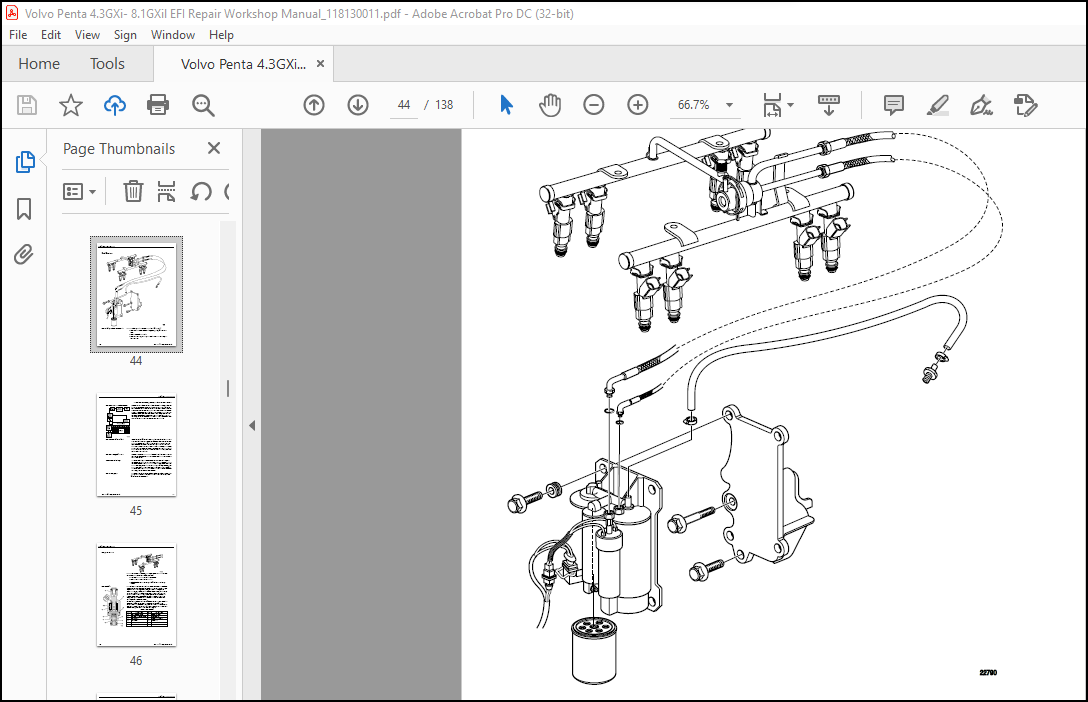
Fuel Supply Components (Typical) 45
Fuel Pump Electrical Circuit 45
Fuel Feed and Return Pipes 45
Quick-Connect Fittings 45
Fuel Pipe O-Rings 45
Fuel Rail Assembly 46
Fuel Injectors 46
Table 1: Fuel Injector 46
Fuel Pressure Regulator Assembly 47
Table 2: Fuel Pressure Regulator 47
Throttle Body Assembly 47
Idle Air Control (IAC) Valve 48
Table 3: Idle Air Control Valve Function 48
Table 4: IAC Valve 48
Distributor Ignition (DI) System 48
Crankshaft Position (CKP) Sensor and Reluctor Wheel 49
Camshaft Position (CMP) Sensor and Reluctor Wheel 49
Ignition Coil and ICM 49
Secondary Ignition Components 49
Circuits Affecting Ignition Control 50
Noteworthy Ignition Information 50
Engine Control Module (ECM) 50
Modes of Operation 51
Knock Sensor (KS) System 51
Purpose 51
Operation 51
4 Upper fail region 51
5 Knock sensor calculated average 51
6 Knock sensor signal 51
7 Lower fail region 51
RPM Reduction and Warnings Table 52
Table 5: RPM Reduction and Warnings 52
IAT 52
Oil 52
Pressure 52
ECT 52
MAP 52
EGT 52
Baro 52
Pressure 52
Knock 52
Sensors 52
Battery 52
Voltage 52
5V 52
External 52
Throttle 53
Position 53
Sensor 53
(TPS) 53
Engine 53
Speed 53
Fuel 53
Injector 53
Driver 53
Fuel 53
Pump 53
Relay 53
Control/ 53
Coil 53
Ignition 53
Relay 53
Control/ 53
Coil 53
Buzzer 53
Control 53
MIL 53
Control 53
IAC 53
Gauge 53
Diagnostics 53
Cam/ 54
Crank 54
Sensors 54
Internal 54
Processor 54
Diagnostics 54
J1939 54
Network 54
(EVC) 54
ECM Pin Function 55
Table 6: ECM pin function 4 3L, 5 0L, 5 7L 55
Section 4: On Board Repair – 4 3L, 5 0L, and 5 7L 57
Repair Instructions 58
Fuel Control On-Board Service 58
Fuel Pressure Relief Procedure 58
1 Disconnect negative battery cable to avoid possible fuel discharge if an accidental attempt is made to start the engine 58
2 Connect fuel pressure gauge J 34730-1 to fuel pressure connector assembly Wrap a shop towel around fitting while connecting the gauge to avoid any spillage 58
3 Install bleed hose into an approved container and open valve to bleed system pressure Fuel connections are now safe for servicing 58
4 Drain any fuel remaining in the gauge into an approved container 58
Engine Cover 59
Remove 59
1 Turn Ignition OFF 59
2 Thumb screw nuts 59
3 Engine cover 59
Install 59
1 Place engine cover on studs 59
2 Thumb screws nuts 59
3 Finger tighten thumb screw nuts securely 59
Fuel Pressure Relief Procedure 59
1 Turn the ignition OFF 59
2 Disconnect the negative battery cable in order to avoid possible fuel discharge if an accidental attempt is made to start the engine 60
3 Remove the engine cover See “Engine Cover” on page 55 60
4 Connect the 3855353 fuel pressure gauge to the fuel pressure valve Wrap a shop towel around the fitting while connecting the gauge in order to avoid spillage 60
5 Install the bleed hose of the gauge into an approved container 60
6 Open the valve on the gauge to bleed the system pressure The fuel connections are now safe for servicing 60
7 Drain any fuel remaining in the gauge into an approved container 60
Quick Connect Fittings Service 60
Tools Required 60
Removal 60
1 Relieve the fuel system pressure before servicing an fuel system connection See “Fuel Pressure Relief Procedure” on page 55 60
2 Remove the retainer from the quick-connect fitting 60
3 Blow dirt out of the fitting using compressed air 60
4 Using Volvo Penta 885384 Fuel Line Disconnect Tool, insert the tool into the female connector, then push inward in order to release 60
5 Pull the connection apart 61
6 Use a clean shop towel in order to wipe off the male pipe end 61
7 Inspect both ends of the fitting for dirt and burrs Clean or replace the components as required 61
Installation 61
1 Apply a few drops of clean engine oil to the male pipe end 61
2 Push both sides of the fitting together in order to snap the retaining tabs into place 61
3 Once installed, pull on both sides of the fitting in order to make sure the connection is secure 61
4 Install the retainer to the quick-connect fitting 61
Flame Arrestor 61
Remove 61
1 Engine cover See “Engine Cover” on page 55 61
2 Flame arrestor retaining screws 61
3 Flame arrestor 61
Inspect 61
Install or Connect 61
1 Flame arrestor to throttle body 61
2 Flame arrestor retaining screws to flame arrestor 61
3 Tighten screws to 14-16 in lb 61
Engine Control Module (ECM) 61
Removal 62
1 Shut the battery power switch OFF or, Disconnect the negative battery cable if a battery switch is unavailable 62
2 Disconnect the connector from ECM 62
3 Remove the four ECM mounting screws 62
4 Remove the ECM from mounting bracket 62
Installation 62
1 Install the new ECM to the mounting bracket 62
2 Install the three ECM mounting screws Tighten the screw to 10- 14 Nm (88-124 lb in) 62
3 Reconnect the connector to the ECM 62
4 Turn ON the battery switch if equipped or, reconnect the negative battery cable 62
System/Ignition Relay 63
Table 1: Fuse Box 63
Removal 63
1 Turn the ignition OFF 63
2 Open the cover 63
3 Remove the system/ignition relay (E) from the socket 63
Installation 63
1 Install the system relay in the socket 63
2 Close the cover 63
Fuel Pump Relay 63
Removal 63
1 Turn the ignition OFF 63
2 Open the cover 63
3 Remove the fuel pump relay (D) from the socket 63
Installation 63
1 Install the fuel pump relay 63
2 Close the cover 64
Engine Coolant Temperature Sensor (ECT) 64
Removal 64
1 Turn OFF the ignition 64
2 Drain the cooling system below the level of the ECT sensor if equipped with closed cooling 64
3 Disconnect the ECT electrical connector 64
4 Remove the ECT sensor 64
Installation 64
1 Install the ECT sensor Tighten the ECT sensor to 20 Nm (15 ft lb ) 64
2 Reconnect the ECT electrical connector 64
3 Refill the cooling system if equipped with closed cooling 64
T-MAP Sensor 64
Removal 64
1 Loosen the fasteners from the engine cover 64
2 Remove the engine cover See “Engine Cover” on page 55 64
3 Disconnect the manifold absolute pressure (MAP) sensor electrical connector 64
4 Remove the T-MAP sensor retaining bolt and washer 64
5 Remove the T-MAP sensor from the intake manifold 64
6 Inspect the T-MAP sensor seal for wear or damage and replace as necessary 64
Installation 64
1 Install the T-MAP sensor 64
2 Install the T-MAP sensor retaining bolt and washer Tighten the MAP sensor retaining bolt to 12 Nm (106 in lb ) 64
3 Connect the T-MAP sensor electrical connector 64
4 Install the intake manifold engine cover Tighten the engine cover fasteners 64
Throttle Position Sensor (TPS) 65
Removal 65
1 Turn OFF ignition and remove the keys to prevent someone from inadvertently starting the engine 65
2 Remove the engine cover See “Engine Cover” on page 55 65
3 Disconnect the throttle position sensor wiring harness connector 65
4 Remove the mounting screws (1) from the TP sensor 65
5 Remove the TP sensor (2) and gasket (3) from the throttle body assembly 65
Installation 65
1 With the throttle valve closed, install the TP sensor on the throttle shaft Rotate the TP sensor counter-clockwise in order to align the mounting holes 65
2 Install the TP sensor mounting screws Tighten the screws to 2 Nm (18 in lb ) 65
3 Connect the TP sensor harness 65
4 Install the engine cover 65
Idle Air Control Valve (IAC) 65
Removal 65
1 Turn OFF ignition and remove the keys to prevent someone from inadvertently starting the engine 65
2 Remove the engine cover See “Engine Cover” on page 55 65
3 Remove the IAC valve attaching screws 66
4 Remove the IAC valve assembly 66
5 Remove the O-ring 66
Cleaning and Inspection 66
1 1 Clean the IAC valve O-ring sealing surface, the pintle valve seat, and the air passage 66
a Use a carburetor cleaner and a parts cleaning brush in order to remove any carbon deposits Follow the instructions on the container 66
b Do not use a cleaner that contains methyl ethyl ketone MEK is an extremely strong solvent and not necessary for this type of deposit 66
c Shiny spots on the pintle or seat are normal and do not indicate misalignment or a bent pintle shaft 66
d If the air passage has heavy deposits, remove the throttle body for a complete cleaning Refer to Throttle Body Assembly and to Throttle Body Cleaning Procedure 66
2 Inspect the IAC valve O-ring for cuts, cracks, or distortion Replace the O-ring if damaged 66
Installation 66
1 Measure the distance between tip of the IAC valve pintle and the mounting flange If the distance (A) is more than 28 mm (1 1 66
2 Lubricate the IAC valve O-ring with clean engine oil 66
3 Install the IAC valve assembly 66
4 Install the attaching screws Tighten the IAC valve screws to 3 Nm (27 in lb ) 66
5 Connect the IAC wire harness connector 67
6 Install the engine cover See “Engine Cover” on page 55 67
7 Reset the IAC valve pintle position 67
IAC Valve Reset Procedure 67
a Turn ON the ignition for 5 seconds, leaving the engine OFF 67
b Turn OFF the ignition for 10 seconds 67
c Start the engine 67
d Check for the proper idle speed 67
Throttle Body Assembly 67
Removal 67
1 Turn OFF ignition and remove the keys to prevent someone from inadvertently starting the engine 67
2 Remove the engine cover See “Engine Cover” on page 55 67
3 Remove the flame arrestor See “Fuel Pressure Relief Procedure” on page 55 67
4 Remove throttle linkage 67
5 Disconnect the IAC and TP sensor wiring harness connectors 67
6 Remove the throttle body retaining screws 67
7 Remove the throttle body assembly 67
8 Discard the throttle body seal 67
9 Clean the gasket surface on the intake manifold 68
Installation 68
1 Install the throttle body assembly with a new seal 68
2 Install the throttle body assembly retaining studs 68
3 Tighten the studs to 9 Nm (80 in lb ) 68
4 Connect the IAC and TP sensor wire harness connectors 68
5 Reconnect the throttle linkage 68
6 Install the flame arrestor See “Fuel Pressure Relief Procedure” on page 55 68
7 Install the engine cover See “Engine Cover” on page 55 68
Throttle Body Cleaning 68
1 Inspect the throttle body bore and the throttle valve plate for deposits You must open the throttle valve in order to inspect all of the surfaces 68
2 Clean the throttle body bore and the throttle valve plate using a clean shop towel with commercially available Throttle Body Cleaner 69
3 If the deposits are excessive, remove and disassemble the throttle body for cleaning Refer to the following procedures: 69
4 After disassembly, clean the throttle body using a parts cleaning brush DO NOT immerse the throttle body in any cleaning solvent 69
5 5 If you removed and disassembled the throttle body for cleaning, assemble and install the throttle body Refer to the following procedures: 69
Fuel Rail Assembly 70
Removal 70
1 Relieve the fuel system pressure See “Fuel Pressure Relief Procedure” on page 54 70
2 Remove the engine cover 70
3 Before removal, clean the fuel rail assembly with a spray type engine cleaner, if necessary Do not soak fuel rails in liquid cleaning solvent 70
4 Remove the upper engine wiring harness bracket studs and position the upper engine wire harness aside 70
5 Identify the connectors to their corresponding injectors to ensure correct injector firing order after re-assembly 70
6 Slide the top portion of the injector connector up until it clicks There should be a click when the slide reaches the end of its stroke Do not pull the top portion of the connector past the stop tabs 70
7 Press the tab on the upper portion of the injector connector in order to release the connector from the injector 70
8 Repeat steps 6 and 7 for each injector connector 70
9 Disconnect the fuel feed and return pipes (1), (2) from the fuel rail See “Quick Connect Fittings Service” on page 56 70
10 Disconnect the fuel pressure regulator vacuum line (3) 70
11 Remove the fuel rail attaching bolts (4) 70
12 Remove the fuel rail assembly (3) 70
13 Remove the injector lower O-ring seal from the spray tip end of each injector 71
14 Discard the O-ring seals 71
Installation 71
1 Lubricate the new lower injector O-ring seals with clean engine oil 71
2 Install the new O-ring seals on the spray tip end of each injector 71
3 Install the fuel rail assembly (1) to the intake manifold 71
4 Apply a 5 mm (0 020 in) band of Volvo Penta 8701528 or Loctite® 243 threadlock to the threads of the fuel rail attaching bolts 71
5 5 Install the fuel rail attaching bolts (2) Tighten the fuel rail attaching bolts to 12 Nm (106 lb in) 71
6 Connect the fuel pressure regulator vacuum line (3) 71
7 Connect the fuel feed and return lines (2) and (1) to the fuel rail See “Quick Connect Fittings Service” on page 56 71
8 Connect the injector electrical connectors as follows: 71
a Install each connector on the proper injector to ensure correct injector firing order 71
b Rotate the injectors as required to avoid stretching the wire harness 71
9 Reconnect engine power 71
10 Inspect for leaks 71
a Turn the ignition ON for 5 seconds 71
b Turn the ignition OFF for 10 seconds 71
c Turn the ignition ON 71
d Inspect for fuel leaks 71
11 Install the engine cover See “Engine Cover” on page 55 72
Fuel Pressure Regulator 72
Removal 72
1 Relieve the fuel system pressure See “Fuel Pressure Relief Procedure” on page 55 72
2 Disconnect the pressure regulator vacuum line 72
3 Clean any dirt from the fuel pressure regulator retainer and the surrounding area 72
4 Remove the fuel pressure regulator retainer (2) 72
5 Remove the fuel pressure regulator (1) from its housing 72
Clean and Inspect 72
Installation 72
1 Install the backup ring (3) on the fuel pressure regulator (if equipped ) 72
2 Install the large O-ring (4) onto the fuel pressure regulator 72
3 Install the filter screen (5) onto the fuel pressure regulator 72
4 Install the small O-ring (6) onto the fuel pressure regulator 72
5 Lubricated the fuel pressure regulator O-rings with a small amount of clean engine oil 72
6 Push the fuel pressure regulator in its housing on the fuel rail 72
7 Install a new fuel pressure regulator retainer (2) 72
8 Connect the fuel pressure regulator vacuum line 72
9 Reconnect the battery power to the engine 72
10 Inspect for leaks 72
a Turn the ignition ON for 5 seconds 72
b Turn the ignition OFF for 10 seconds 72
c Turn the ignition ON 72
d Inspect for fuel leaks 72
11 Install the engine cover See “Engine Cover” on page 55 72
Fuel Injector 72
Removal 72
1 Relieve the fuel pressure See “Fuel Pressure Relief Procedure” on page 54 72
2 Remove the fuel rail assembly See “Fuel Rail Assembly” on page 66 73
3 Remove the injector retainer clip 73
4 Insert the fork of tool J 43013 between the fuel rail pod and the 3 protruding retaining clip edges Use a prying potion while inserting the tool to force the injector out of the pod 73
5 Discard the injector retaining clip 73
6 Remove the injector O-ring seals from both ends of the injector Discard the O-ring seals 73
Installation 73
7 Lubricate the new O-ring seals with clean engine oil 73
8 Install the new injector O-ring seals on the injector 73
9 Install a new retainer clip on the injector 73
10 Push the fuel injector into the fuel rail socket with the electrical connector facing outwards The retainer clip locks on to a flange on the fuel rail injector socket 73
11 Install the fuel rail assembly Fuel Rail Assembly” on page 66 73
Distributor 74
Removal 74
1 Turn OFF the ignition 74
2 Remove the engine cover See “Engine Cover” on page 55 74
3 Remove the spark plug wires from the distributor cap 74
4 Remove the electrical connector from the base of the distributor 74
5 Remove the 2 screws that retain the distributor cap to the housing 74
6 Discard the screws 74
7 Remove the distributor cap from the housing 74
8 Use a grease pencil in order to mark the position of the rotor in relation to the distributor housing (1) 74
9 Mark the distributor housing and the intake manifold with the grease pencil 74
10 Remove the mounting clamp hold-down bolt 75
11 As the distributor is being removed from the engine, watch the rotor move in a counter-clockwise direction about 42 degrees This will appear as slightly more than one clock position 75
12 Note the position of the rotor segment 75
13 Remove the distributor 76
14 Place a second mark on the base of the distributor (2) This will aid in achieving the proper rotor alignment during the distributor installation 76
Installation 76
1 If installing a new distributor assembly, place 2 marks on the new distributor housing in the same location as the marks on the original housing 76
2 Remove the new distributor cap, if necessary 76
3 Align the rotor with the second mark (2) 76
4 Guide the distributor into the engine 76
5 Align the hole in the distributor hold-down base over the mounting hole in the intake manifold 76
6 As the distributor is being installed, observe the rotor moving in a clockwise direction about 42 degrees 76
7 Once the distributor is completely seated, the rotor segment should be aligned with the mark on the distributor housing 76
a If the rotor segment is not aligned with the mark, the driven gear teeth and the camshaft have meshed one or more teeth out of alignment 76
b In order to correct this condition, remove and reinstall the distributor 76
8 Install the distributor mounting clamp bolt Tighten the bolt to 25 Nm (18 ft lb ) 77
9 Install the distributor cap 77
10 Install the new distributor cap screws Tighten the screws to 2 4 Nm (21 in lb ) 77
11 Install the electrical connector to the distributor 77
12 Install the spark plug wires to the distributor cap 77
13 Install the ignition coil wire to the distributor cap 77
14 Install the engine cover See “Engine Cover” on page 55 77
Ignition Coil 78
Removal 78
1 Remove the engine cover See “Engine Cover” on page 55 78
2 Disconnect the electrical connectors from the ignition coil and ignition module (1) 78
3 Remove the ignition coil wire (2) 78
4 Remove the nut and bolt holding the bracket and the ignition coil to the flywheel housing 78
5 Remove the bracket and the ignition coil assembly 78
Installation 78
1 Install the ignition coil to the bracket with the 2 screws 7-9 Nm (5- 7 ft lb ) 78
2 Install the ignition coil and the bracket to the intake manifold with studs Tighten the nut and screw to 34-39 Nm (20-25 ft lb ) 78
3 Install the ignition coil wire (2) 78
4 Install the electrical connectors 78
5 Install the engine cover See “Engine Cover” on page 55 78
Ignition Control Module 79
Removal 79
1 Remove the engine cover See “Engine Cover” on page 55 79
2 Disconnect the electrical connector (3) 79
3 Remove the screws (4) holding the ignition control module (2) and the heat sink (1) to the bracket 79
4 Remove the ignition control module and the heat sink 79
Installation 79
1 Install the ignition control module (2) and the heat sink (1) on the bracket with the screws (4) Tighten the screws to 3 5 Nm (31 in lb ) 79
2 Reconnect the electrical connector (3) 79
3 Install the engine cover See “Engine Cover” on page 55 79
Fuel Cell 80
Removal 80
1 Disconnect negative battery cable 80
2 Relieve the fuel system pressure before servicing any fuel system component See “Fuel Pressure Relief Procedure” on page 55 80
3 Clean all the fuel fitting connections and the surrounding areas before disconnecting the fuel pipes in order to avoid possible contamination of the fuel system 80
4 Disconnect the threaded fittings from the fuel cell 80
5 Cap the fuel pipes in order to prevent possible fuel system contamination 80
6 Disconnect the fuel pump electrical connectors 80
7 Disconnect the cooling lines to the fuel cell 80
8 Remove the fuel filter and dispose of it in an approved manner 80
9 Remove the 4 retaining screws and retain for installation on the new fuel cell 80
10 Remove the fuel cell 80
Installation 80
1 Install the fuel cell 80
2 Reconnect the fuel pump electrical connectors 80
3 Remove the caps from the fuel pipes 80
4 Reconnect the threaded fittings into the fuel pump Tighten the fittings to 25 Nm (18 ft lb ) 80
5 Reconnect the cooling lines 80
6 If a fuel filter does not come installed on the new fuel cell, install a new fuel filter 80
7 Connect the negative battery cable 80
8 Inspect for leaks 80
a Turn the ignition ON for 5 seconds 80
b Turn the ignition OFF for 10 seconds 80
c Turn the ignition ON 80
d Inspect for fuel leaks 80
High Pressure Fuel Pump Replacement 81
1 Disconnect the negative battery cable 81
2 Relieve the fuel system pressure before servicing any fuel system component See “Fuel Pressure Relief Procedure” on page 55 81
3 Clean all the fuel fitting connections and the surrounding areas before disconnecting the fuel pipes in order to avoid possible contamination of the fuel system 81
4 Use a small container or shop towel an place below the high pressure fuel pump to catch any fuel that will be spilled when the pump is removed 81
5 Using fuel pressure test kit P/N 3855533 connect hose (B) of the tester to the fuel pressure test port on the fuel cell Open the bleed valve on the pressure tester (C) and drain the fuel cell into an approved container 81
6 Disconnect the high pressure fuel pump’s electrical connector (K) 81
7 Disconnect the fuel line (I) using a 7/8 inch wrench (M) to support the pump outlet (H) and a 5/8 inch wrench (L) to disconnect the fuel line nut (I) 82
8 Using a T-20 Torx® screwdriver head in a ratchet wrench, remove the retaining bracket screw (N) 82
9 Remove the fuel pump retaining bracket (G) 82
10 Remove the pump by twisting and pulling upward on the pump by hand 82
11 If you are unable to remove the fuel pump by twisting and pulling up on the fuel pump by hand, you may use a screwdriver to 83
Installation 83
1 Remove the new fuel pump for its packaging and inspect the ends of the pump for damage Be sure that the O-rings are installed If they are not installed, use the O-rings that come with the pump 83
2 Lubricate the O-rings with 1 drop of clean engine oil 83
3 Place the new high pressure fuel pump onto the fuel cell housing by sliding into place Be sure the pump is fully seated 83
4 Install fuel pump clamp and install a new Torx head screw Tighten to 5 1-6 2 Nm (45-55 in lb ) 83
5 Install a new O-ring on the fuel line and re-attach the fuel line Using a 7/8 in wrench to counter-hold the regulator housing, tighten the nut to 16 9-20 3 Nm (12-15 ft lb ) with a 5/8 in wrench 83
6 Reconnect the electrical connection 83
7 Reconnect the negative battery cable 83
Spark Plug 84
Removal 84
1 Remove the spark plug wires See “Spark Plug Wire Replacement” on page 80 84
2 Loosen each spark plug one or two turns 84
3 Brush or air blast away any dirt from around the spark plugs 84
4 Remove the spark plugs one at a time and place each plug in a tray marked with the corresponding cylinder numbers 84
Installation 84
1 Inspect each spark plug gap Adjust each plug gap as needed Spark plug gap: 1 524 mm (0 060 in) 84
2 Install the spark plugs Tighten the spark plugs to 20 Nm (15 ft lb ) 84
3 Install the spark plug wires See “Spark Plug Wire Replacement” on page 80 84
Spark Plug Wire Inspection 84
1 Correct routing of the spark plug wires Incorrect routing may cause cross-firing 84
2 Any signs of cracks or splits in the wires 84
3 Inspect each boot for the following conditions: 84
a Tearing 84
b Piercing 84
c Arcing 84
d Carbon tracking 84
e Corroded terminal 84
Spark Plug Wire Replacement 84
Removal 84
1 Disconnect the spark plug wire at each spark plug 84
a Twist each spark plug wire 1/2 turn 84
b Pull only on the boot in order to remove the wire from each spark plug 84
2 Disconnect the spark plug wire from each ignition coil 84
a a) Twist each spark plug wire 1/2 turn 84
b b) Pull only on the boot in order to remove the wire from each ignition coil 84
Installation 84
1 Install the spark plug wire at each ignition coil 84
2 Install the spark plug wire at each spark plug 84
3 Inspect the wires for proper installation: 84
a Push sideways on each boot in order to inspect the seating 85
b Reinstall any loose boot 85
Spark Plug Inspection 85
Spark Plug Usage 85
1 Ensure that the correct spark plug is installed An incorrect spark plug causes driveability conditions 85
2 Ensure that the spark plug has the correct heat range An incorrect heat range causes the following conditions: 85
a Spark plug fouling – colder plug 85
b Pre-ignition causing spark plug and/or engine damage – hotter plug 85
3 Inspect the terminal post (1) for damage 85
a Inspect for a bent or broken terminal post (1) 85
b Inspect the spark plug boot for damage 85
c Inspect the spark plug recess area of the cylinder head for moisture, such as oil, coolant or water A spark plug boot that is saturated causes arcing to ground 85
4 Inspect the insulator (2) for cracks All or part of the electrical charge may arc through the crack instead of the electrodes (3, 4) 85
5 5 Inspect for evidence of improper arcing 85
a Measure the gap between the center electrode (4) and the side electrode (3) terminals An excessively wide electrode gap can prevent correct spark plug operation 85
b Inspect for the correct spark plug torque Insufficient torque can prevent correct spark plug operation An over torqued spark plug may cause the insulator (2) to crack 85
c Inspect for signs of tracking that occurred near the insulator tip instead of the center electrode (4) 85
d Inspect for a broken or worn side electrode (3) 85
e Inspect for a broken, worn or loose center electrode (4) by shaking the spark plug 85
6 A rattling sound indicates internal damage 85
7 A loose center electrode (4) reduces the spark intensity 85
a Inspect for bridged electrodes (3, 4) Deposits on the electrodes (3, 4) reduce or eliminates the gap 85
b Inspect for worn or missing platinum pads on the electrodes (3, 4), if equipped 85
c Inspect for excessive fouling 85
8 Inspect the spark plug recess area of the cylinder head for debris Dirty or damaged threads can cause the spark plug not to seat correctly during installation 85
Spark Plug Visual Inspection 85
1 Normal Operation – Brown to greyish-tan with small amounts of white powdery deposits are normal combustion by-products from fuels with additives 85
2 Carbon Fouled – Dry, fluffy black carbon, or soot caused by rich fuel mixtures 85
3 Leaking fuel injectors 86
4 Excessive fuel pressure 86
5 Restricted flame arrestor/air filter element 86
6 Incorrect combustion Reduced ignition system voltage output 86
7 Weak coil(s) 86
8 Worn ignition wires 86
9 Incorrect spark plug gap Excessive idling or slow speeds under light loads can keep spark plug temperatures so low that normal combustion deposits may not burn off 86
10 Inspect for evidence of improper arcing 86
a Measure the gap between the center electrode (4) and the side electrode (3) terminals An excessively wide electrode gap can prevent correct spark plug operation 86
b Inspect for the correct spark plug torque Insufficient torque can prevent correct spark plug operation An over torqued spark plug may cause the insulator (2) to crack 86
c Inspect for signs of tracking that occurred near the insulator tip instead of the center electrode (4) 86
d Inspect for a broken or worn side electrode (3) 86
e Inspect for a broken, worn or loose center electrode (4) by shaking the spark plug 86
11 A rattling sound indicates internal damage 86
12 A loose center electrode (4) reduces the spark intensity 86
a Inspect for bridged electrodes (3, 4) Deposits on the electrodes (3, 4) reduce or eliminates the gap 86
b Inspect for worn or missing platinum pads on the electrodes (3, 4), if equipped 86
c Inspect for excessive fouling 86
13 Inspect the spark plug recess area of the cylinder head for debris Dirty or damaged threads can cause the spark plug not to seat correctly during installation 86
Crankshaft Position (CKP) Sensor 87
Removal 87
1 Disconnect the negative battery cable 87
2 Disconnect the CKP sensor harness connector 87
3 Remove the CKP sensor mounting bolt 87
4 Remove the CKP sensor 87
Installation 87
1 Replace the CKP sensor O-ring 87
2 Lubricate the O-ring with clean engine oil before installing the CKP sensor 87
3 Install the CKP sensor 87
4 Install the CKP sensor mounting bolt Tighten the CKP sensor mounting bolt to 9 Nm (80 in lb ) 87
5 Connect the CKP sensor harness connector 87
Camshaft Position Sensor (CMP) 88
Removal 88
1 Remove the engine cover See “Engine Cover” on page 55 88
2 Disconnect the spark plug wires and ignition coil wire from the distributor See “Spark Plug Wire Replacement” on page 80 88
3 Disconnect the camshaft position (CMP) sensor harness connector from the distributor 88
4 Remove the distributor cap screws (1) See “Distributor” on page 70 88
5 Remove the distributor cap 88
6 Remove the rotor screws (2) 88
7 Align the square slot in the reluctor wheel with the CMP sensor 89
8 Remove CMP sensor screws (3) 89
9 Remove the CMP sensor 89
Installation 89
1 Insert the CMP sensor through the reluctor wheel slot 89
2 Install new CMP mounting screws Tighten the screws to 2 2 Nm (19 in lb ) 89
3 Install the rotor onto the reluctor wheel 89
4 Install new rotor screws Tighten the screws to 2 Nm (18 in lb ) 89
5 Install distributor cap See “Distributor” on page 70 89
6 Reinstall the spark plug wires in their original locations 89
7 Install engine cover See “Engine Cover” on page 55 89
Knock Sensor 90
Removal 90
1 Disconnect the negative battery cable 90
2 Remove the engine cover See “Engine Cover” on page 55 90
3 Disconnect the knock sensor harness connector 90
4 Remove the knock sensor from drain tee 90
Installation 90
1 Install the knock sensor in drain tee 90
2 Tighten the sensor to 18 Nm (13 ft lb ) 90
3 Connect the knock sensor harness connector 90
4 Connect the negative battery cable 90
Ignition System Specifications – 5 0L and 5 7L 91
Metric 91
English 91
1-8-4-3-6-5-7-2 91
5,000 Ohms/ft 91
27 Nm 91
20 ft lb 91
1 524 mm 91
0 060 91
Volvo Penta P/N 3861632 91
42 degrees 91
Fuel System Specifications 91
Metric 91
English 91
55 kPa 91
8 psi 91
344-413 kPa 91
50-60 psi 91
Fastener Tightening Specifications 91
Metric 91
English 91
2 2 Nm 91
19 in lb 91
9 Nm 91
80 in lb 91
2 4 Nm 91
21 in lb 91
25 Nm 91
18 ft lb 91
2 Nm 91
18 in lb 91
7-11 Nm 91
61-97in lb 91
20 Nm 91
15 ft lb 91
1 5-1 8 Nm 91
14-16 in lb 91
5 1-6 2 Nm 91
45-55 in lb 91
12 Nm 91
106 in lb 91
16 9-20 3 Nm 91
12-15 ft lb 91
3 Nm 91
27 in lb 91
7-9 Nm 91
5-7 ft lb 91
3 5 Nm 91
31 in lb 91
18 Nm 91
13 ft lb 91
15 Nm 91
11 ft lb 91
9 Nm 91
80 in lb 91
2 Nm 91
18 in lb 91
12 Nm 91
106 in lb 91
Section 5: Operation – 8 1L 93
General Description 94
Basic Knowledge Required 94
ECM Service Precautions 94
Engine Control Module (ECM) 94
Malfunction Indicator Lamp (MIL) 95
Soft Warning 95
Hard Warning 95
RPM Reduction Mode 95
Power Derate 95
Low Rev Limit 95
Forced Idle 96
Engine Shutdown 96
Input Sensors 96
Output Actuators 96
Fuel System 97
Fuel Feed Pipe 97
Quick-Connect Fittings 98
Fuel Pipe O-Rings 98
Fuel Rail Assembly 98
Fuel Injectors 98
FUel Pressure Regulator Assembly 99
Fuel Metering Modes of Operation 99
Starting Mode 99
Run Mode 99
Acceleration Mode 99
Deceleration Mode 99
Battery Correction Mode 100
Fuel Cutoff Mode 100
Electronic Ignition (EI) System 100
Crankshaft Position (CKP) Sensor and Reluctor Wheel 100
Camshaft Position (CMP) Sensor and Reluctor Wheel 101
Ignition Coils 101
Circuits Affecting Ignition Control 101
Noteworthy Ignition Information 102
Engine Control Module (ECM) 102
Knock Sensor (KS) System 102
Purpose 103
Operation 103
6 Upper fail region 103
7 Knock sensor calculated average 103
8 Knock sensor signal 103
9 Lower fail region 103
ECM Pinout 108
Table 2: ECM pin function 8 1L 108
Section 6: On Board Repair – 8 1L 109
Engine Control Module (ECM) 109
Removal 110
1 Disconnect battery power from the engine 110
2 Slide the connector lock to the unlocked position (1) 110
3 Disconnect the connector from ECM (2) 110
4 Remove four ECM mounting screws 110
5 Remove the ECM from mounting bracket 110
Installation 110
1 Install the new ECM to the mounting bracket 110
2 Install the four ECM mounting screws Tighten the screw to 10-14 Nm (88-124 lb in) 110
3 Reconnect the connector to the ECM (2) 110
4 Slide the connector lock to the locked position (2) 110
5 Reconnect battery power to the engine 110
System/Ignition Relay 111
Table 1: Fuse Box 111
Removal 111
1 Turn the ignition OFF 111
2 Open the cover 111
3 Remove the system/ignition relay (E) from the socket 111
Installation 111
1 Install the system relay in the socket 111
2 Close the cover 111
Fuel Pump Relay 111
Removal 111
1 Turn the ignition OFF 111
2 Open the cover 111
3 Remove the fuel pump relay (D) from the socket 111
Installation 112
1 Install the fuel pump relay 112
2 Close the cover 112
Engine Coolant Temperature Sensor (ECT) 112
Removal 112
1 Turn OFF the ignition 112
2 Drain the cooling system below the level of the ECT sensor if equipped with closed cooling 112
3 Disconnect the ECT electrical connector 112
4 Remove the ECT sensor 112
Installation 112
1 Install the ECT sensor Tighten the ECT sensor to 20 Nm (15 ft lb ) 112
2 Reconnect the ECT electrical connector 112
3 Refill the cooling system if equipped with closed cooling 112
Engine Cover 112
Removal 112
1 Turn engine OFF and remove key from ignition to prevent inadvertent starting 112
2 Using a 10 mm socket and ratchet, remove the engine cover retaining screws 112
3 Remove the engine cover 112
Installation 112
1 Place engine cover on intake manifold and align mounting holes with the engine cover 112
2 Install the engine cover retaining screws 112
3 Tighten the engine cover retaining screws to 6-10 Nm (53-88 in lb ) 112
(MAP) Manifold Absolute Pressure 113
Removal 113
1 Loosen the fasteners (4) from the intake manifold engine cover 113
2 Remove the engine cover from the intake manifold (2) 113
3 Disconnect the manifold absolute pressure (MAP) sensor electrical connector 113
4 Remove the MAP sensor retaining bolt and washer (1) 113
5 Remove the MAP sensor (3) from the intake manifold (2) 113
6 Inspect the MAP sensor seal for wear or damage and replace as necessary 113
Installation 113
1 Install the MAP sensor (3) 113
2 Install the MAP sensor retaining bolt and washer (1) Tighten the MAP sensor retaining bolt to 12 Nm (106 lb in ) 113
3 Connect the MAP sensor electrical connector (2) 113
4 Install the intake manifold engine cover (1) Tighten the engine cover fastener to 10 Nm (89 lb in) 113
(MAT) Manifold Air Temperature Sensor 113
Removal 113
1 Disconnect the manifold air temperature (MAT) sensor electrical connector 113
2 Using a 19 mm (3/4 in ) wrench, remove the MAT sensor from the rear of the intake manifold 113
Installation 113
1 Coat the threads of the new MAT sensor with Volvo Penta P/N 1141570 113
2 Install sensor in the intake manifold 113
3 Tighten the sensor to 40 Nm (29 ft lb ) 113
4 Reconnect electrical connector 113
Flame Arrestor 114
Removal 114
1 Turn ignition OFF 114
2 Loosen the flame arrestor element retaining clamp 114
3 Remove the flame arrestor element 114
Installation 114
1 Install the flame arrestor element to the throttle body 114
2 Tighten the flame arrestor retaining clamp to flame arrestor element 114
Throttle Body Assembly 114
Removal 114
1 Disconnect the negative battery cable 114
2 Disconnect the wiring harness connector 114
3 Remove the flame arrestor (if applicable) 114
4 Remove the throttle body assembly attaching nuts 114
5 Remove the throttle body assembly and gasket 114
6 Discard the gasket 114
Inspect 114
Installation 115
1 Install a new throttle body gasket 115
2 Install the throttle body assembly and the throttle body assembly attaching nuts Tighten the throttle body assembly attaching nuts to 10 Nm (89 lb in) 115
3 Reconnect the electrical connector 115
4 Install the flame arrestor 115
5 Reconnect the negative battery cable 115
Fuel Pressure Relief Procedure 116
1 Turn the ignition OFF 116
2 Disconnect the negative battery cable in order to avoid possible fuel discharge if an accidental attempt is made to start the engine 116
3 Remove the engine cover See “Engine Cover” on page 108 116
4 Connect the 3855353 fuel pressure gauge to the fuel pressure valve Wrap a shop towel around the fitting while connecting the gauge in order to avoid spillage 116
5 Install the bleed hose of the gauge into an approved container 116
6 Open the valve on the gauge to bleed the system pressure The fuel connections are now safe for servicing 116
7 Drain any fuel remaining in the gauge into an approved container 116
Quick Connect Fittings Service 117
Tools Required 117
Removal 117
1 Relieve the fuel system pressure before servicing an fuel system connection See “Fuel Pressure Relief Procedure” on page 112 117
2 Remove the retainer from the quick-connect fitting 117
3 Blow dirt out of the fitting using compressed air 117
4 Using Volvo Penta 885384 Fuel Line Disconnect Tool, insert the tool into the female connector, then push inward in order to release 117
5 Pull the connection apart 117
6 Use a clean shop towel in order to wipe off the male pipe end 117
7 Inspect both ends of the fitting for dirt and burrs Clean or replace the components as required 117
Installation 118
1 Apply a few drops of clean engine oil to the male pipe end 118
2 Push both sides of the fitting together in order to snap the retaining tabs into place 118
3 Once installed, pull on both sides of the fitting in order to make sure the connection is secure 118
4 Install the retainer to the quick-connect fitting 118
Fuel Cell 119
Removal 119
1 Disconnect negative battery cable 119
2 Relieve the fuel system pressure before servicing any fuel system component See “Fuel Pressure Relief Procedure” on page 112 119
3 Clean all the fuel fitting connections and the surrounding areas before disconnecting the fuel pipes in order to avoid possible contamination of the fuel system 119
4 Disconnect the threaded fittings from the fuel cell 119
5 Cap the fuel pipes in order to prevent possible fuel system contamination 119
6 Disconnect the fuel pump electrical connectors 119
7 Disconnect the cooling lines to the fuel cell 119
8 Remove the fuel filter and dispose of it in an approved manner 119
9 Remove the 4 retaining screws and retain for installation on the new fuel cell 119
10 Remove the fuel cell 119
Installation 119
1 Install the fuel cell 119
2 Reconnect the fuel pump electrical connectors 119
3 Remove the caps from the fuel pipes 119
4 Reconnect the threaded fittings into the fuel pump Tighten the fittings to 25 Nm (18 ft lb ) 119
5 Reconnect the cooling lines 119
6 If a fuel filter does not come installed on the new fuel cell, install a new fuel filter 119
7 Connect the negative battery cable 119
8 Inspect for leaks 119
a Turn the ignition ON for 5 seconds 119
b Turn the ignition OFF for 10 seconds 119
c Turn the ignition ON 119
d Inspect for fuel leaks 119
High Pressure Fuel Pump Replacement 120
1 Disconnect the negative battery cable 120
2 Relieve the fuel system pressure before servicing any fuel system component See “Fuel Pressure Relief Procedure” on page 112 120
3 Clean all the fuel fitting connections and the surrounding areas before disconnecting the fuel pipes in order to avoid possible contamination of the fuel system 120
4 Use a small container or shop towel an place below the high pressure fuel pump to catch any fuel that will be spilled when the pump is removed 120
5 Using fuel pressure test kit P/N 3855533 connect hose (B) of the tester to the fuel pressure test port on the fuel cell Open the bleed valve on the pressure tester (C) and drain the fuel cell into an approved container 120
6 Disconnect the high pressure fuel pump’s electrical connector (K) 120
7 Disconnect the fuel line (I) using a 7/8 inch wrench to support the pump outlet (H) and a 5/8 inch wrench to disconnect the fuel line nut (I) 120
8 Using a T-20 Torx® screwdriver head in a ratchet wrench, remove the retaining bracket screw 121
9 Using a Torx® T-20 screwdriver socket and a ratchet, remove three retaining screws holding the pressure regulator to the fuel cell 121
10 Remove the pressure regulator (H) and the fuel pump retaining clamp (G) 121
11 Remove the fuel pump Remove the pump by twisting and pulling upward on the pump by hand 122
12 Replace the O-ring (O) on the return fitting under the pressure regulator casting 122
13 Inspect the regulator O-ring (N) without removing it If it is damaged, the fuel pressure regulator must be replaced P/N 3861279 122
14 If you are unable to remove the fuel pump by twisting and pulling up on the fuel pump, you may use a screwdriver to CAREFULLY pry up on the fuel pump to remove it 122
Installation 122
1 Remove the new fuel pump for its packaging and inspect the ends of the pump for damage Be sure that the O-rings are installed If they are not installed, use the O-rings that come with the pump 122
2 Place the new high pressure fuel pump onto the fuel cell housing by sliding into place Be sure the pump is fully seated 122
3 Install fuel pump clamp and install a new Torx head screw Tighten to 5 1-6 2 Nm (45-55 in lb ) 122
4 Install the pressure regulator casting using new Torx head screws Tighten screws to 4 5-5 6 Nm (40-50 in lb ) 122
5 Install a new O-ring on the fuel line and re-attach the fuel line Using a 7/8 in wrench to counter-hold the regulator housing, tighten the nut to 16 9-20 3 Nm (12-15 ft lb ) with a 5/8 in wrench 123
6 Reconnect the electrical connection 123
7 Reconnect the negative battery cable 123
Fuel Rail Assembly 123
Removal 123
1 Relieve the fuel system pressure See “Fuel Pressure Relief Procedure” on page 112 123
2 Before removal, clean the fuel rail assembly with a spray type engine cleaner, if necessary Do not soak fuel rails in liquid cleaning solvent 123
3 Remove the engine cover and brackets 123
4 Identify and mark the connectors to their corresponding injectors to ensure correct injector firing order after re-assembly 123
5 Identify the connectors to their corresponding injectors to ensure correct injector firing order after re-assembly 123
6 Pull the top portion of the injector connector up Do not pull the top portion of the connector past the top of the white portion 124
7 Push the tab labeled “PRESS” on the lower side of the injector connector in order to release the connector from the injector 124
8 Repeat step 9 and step 10 for each injector connector 124
9 Disconnect the fuel feed from the fuel rail 124
10 Disconnect the fuel pressure regulator vacuum line 124
11 Remove the fuel rail attaching bolts 124
12 Remove the fuel rail assembly 124
13 Remove injector lower O-ring seal (4) from the spray tip end of each injector 125
14 Discard the O-ring seals 125
Installation 125
1 Lubricate the new lower injector O-ring seals with clean engine oil 125
2 Install the new O-ring seals on the spray tip end of each injector 125
3 Install the fuel rail assembly to the intake manifold 125
4 Apply a 5 mm (0 020 in) band of Volvo Penta P/N 1161053 Threadlocking compound to the threads of the fuel rail attaching bolts 125
5 Install the fuel rail attaching bolts Tighten the fuel rail attaching bolts to 12 Nm (106 lb in) 125
6 Connect the fuel pressure regulator vacuum line 125
7 Connect the fuel feed line to the fuel rail 126
8 Connect the injector electrical connectors as follows: 126
a Install each connector on the proper injector in order to ensure correct injector firing order 126
b Rotate the injectors as required in order to avoid stretching the wire harness 126
9 Install the upper engine wire harness bracket 126
10 Install the retainer studs to the upper engine wire harness Tighten the nut to 10 Nm (89 lb in) 126
11 Install the engine cover Tighten the bolts 10 Nm (89 lb in) 127
12 Connect the negative battery cable 127
13 Inspect for leaks 127
a Turn the ignition ON for 5 seconds 127
b Turn the ignition OFF for 10 seconds 127
c Turn the ignition ON 127
d Inspect for fuel leaks 127
Removal 127
1 Relieve the fuel system pressure Fuel Pressure Relief Procedure” on page 112 127
2 Disconnect the fuel pressure regulator vacuum line 127
3 Clean any dirt from the fuel pressure regulator retainer and the surrounding area 128
4 Remove the fuel pressure regulator retainer (9) 128
5 Remove the fuel pressure regulator (8) from the fuel pressure regulator housing 128
Installation 128
1 Install the backup ring (10) on the fuel pressure regulator (8) 128
2 Install the new large O-ring (11) on the fuel pressure regulator 128
3 Install the regulator filter (12) on the fuel pressure regulator 128
4 Install the new small O-ring (13) on the fuel pressure regulator 128
5 Lubricate the fuel pressure regulator large O-ring and the small O- ring with clean engine oil 128
6 Push the fuel pressure regulator into the regulator housing on the fuel rail 128
7 Install a new fuel pressure regulator retainer (9) 128
8 Connect the fuel pressure regulator vacuum line 128
9 Connect the negative battery cable 128
10 Inspect for leaks 128
a Turn the ignition ON for 5 seconds 128
b Turn the ignition OFF for 10 seconds 128
c Turn the ignition ON 128
d Inspect for fuel leaks 128
11 Install the engine cover 128
Removal 129
1 Remove the fuel rail assembly Fuel Pressure Relief Procedure” on page 112 129
2 Remove the injector retainer clip (4) 129
3 Insert the fork of J 43013, the fuel injector assembly removal tool, between the fuel rail pod and the 3 protruding retaining clip ledges Use a prying motion while inserting the tool in order to force the injector out of the fuel rail pod 129
4 Discard the injector retainer clip (1) 129
5 Remove the injector O-ring seals (2), (4) from both ends of the injector Discard the O-ring seals 129
Installation 129
1 Lubricate the new O-ring seals (2), (4) with clean engine oil 130
2 Install the new injector O-ring seals on the injector 130
3 Install a new retainer clip (1) on the injector 130
4 Push the fuel injector (5) into the fuel rail injector socket with the electrical connector facing outwards The retainer clip (4) locks on to a flange on the fuel rail injector socket 130
5 Install the fuel rail assembly See “Fuel Rail Assembly” on page 119 130
Ignition Coil(s) 130
Removal 130
1 Disconnect the spark plug wires at the ignition coils See “Spark Plug Wire Replacement” on page 127 130
2 Disconnect the ignition coil harness connector 130
3 Remove the ignition coil mounting bolts 130
4 Remove the ignition coil 130
Installation 130
1 1 Install the ignition coil 130
2 Install the ignition coil mounting bolts Tighten the ignition coil mounting bolts to 12 Nm (106 lb in) 131
3 Connect the ignition coil harness connector 131
4 Connect the spark plug wires at the ignition coils See “Spark Plug Wire Replacement” on page 127 131
Removal 131
1 Remove the spark plug wires See “Spark Plug Wire Replacement” on page 127 131
2 Loosen each spark plug one or two turns 131
3 Brush or air blast away any dirt from around the spark plugs 131
4 Remove the spark plugs one at a time and place each plug in a tray marked with the corresponding cylinder numbers 131
Installation 131
1 Inspect each spark plug gap Adjust each plug gap as needed Spark plug gap: 1 524 mm (0 060 in) 131
2 Install the spark plugs Tighten the spark plugs to 20 Nm (15 ft lb ) 131
3 Install the spark plug wires See “Spark Plug Wire Replacement” on page 127 131
Spark Plug Wire Inspection 131
1 Correct routing of the spark plug wires Incorrect routing may cause cross-firing 131
2 Any signs of cracks or splits in the wires 131
3 Inspect each boot for the following conditions: 131
a Tearing 131
b Piercing 131
c Arcing 131
d Carbon tracking 131
e Corroded terminal 131
Spark Plug Wire Replacement 131
Removal 131
1 Disconnect the spark plug wire at each spark plug 131
a Twist each spark plug wire 1/2 turn 131
b Pull only on the boot in order to remove the wire from each spark plug 131
2 Disconnect the spark plug wire from each ignition coil 131
a a) Twist each spark plug wire 1/2 turn 132
b b) Pull only on the boot in order to remove the wire from each ignition coil 132
Installation 132
1 Install the spark plug wire at each ignition coil 132
2 Install the spark plug wire at each spark plug 132
3 Inspect the wires for proper installation: 132
a Push sideways on each boot in order to inspect the seating 132
b Reinstall any loose boot 132
Spark Plug Inspection 132
Spark Plug Usage 132
1 Ensure that the correct spark plug is installed An incorrect spark plug causes driveability conditions 132
2 Ensure that the spark plug has the correct heat range An incorrect heat range causes the following conditions: 132
a Spark plug fouling – colder plug 132
b Pre-ignition causing spark plug and/or engine damage – hotter plug 132
3 Inspect the terminal post (1) for damage 132
a Inspect for a bent or broken terminal post (1) 132
b Inspect the spark plug boot for damage 132
c Inspect the spark plug recess area of the cylinder head for moisture, such as oil, coolant or water A spark plug boot that is saturated causes arcing to ground 132
4 Inspect the insulator (2) for cracks All or part of the electrical charge may arc through the crack instead of the electrodes (3, 4) 132
5 5 Inspect for evidence of improper arcing 132
a Measure the gap between the center electrode (4) and the side electrode (3) terminals An excessively wide electrode gap can prevent correct spark plug operation 132
b Inspect for the correct spark plug torque Insufficient torque can prevent correct spark plug operation An over torqued spark plug may cause the insulator (2) to crack 132
c Inspect for signs of tracking that occurred near the insulator tip instead of the center electrode (4) 132
d Inspect for a broken or worn side electrode (3) 132
e Inspect for a broken, worn or loose center electrode (4) by shaking the spark plug 132
6 A rattling sound indicates internal damage 132
7 A loose center electrode (4) reduces the spark intensity 132
a Inspect for bridged electrodes (3, 4) Deposits on the electrodes (3, 4) reduce or eliminates the gap 132
b Inspect for worn or missing platinum pads on the electrodes (3, 4), if equipped 132
c Inspect for excessive fouling 132
8 Inspect the spark plug recess area of the cylinder head for debris Dirty or damaged threads can cause the spark plug not to seat correctly during installation 133
Spark Plug Visual Inspection 133
1 Normal Operation – Brown to greyish-tan with small amounts of white powdery deposits are normal combustion by-products from fuels with additives 133
2 Carbon Fouled – Dry, fluffy black carbon, or soot caused by rich fuel mixtures 133
3 Leaking fuel injectors 133
4 Excessive fuel pressure 133
5 Restricted flame arrestor/air filter element 133
6 Incorrect combustion Reduced ignition system voltage output 133
7 Weak coil(s) 133
8 Worn ignition wires 133
9 Incorrect spark plug gap Excessive idling or slow speeds under light loads can keep spark plug temperatures so low that normal combustion deposits may not burn off 133
10 Inspect for evidence of improper arcing 133
a Measure the gap between the center electrode (4) and the side electrode (3) terminals An excessively wide electrode gap can prevent correct spark plug operation 133
b Inspect for the correct spark plug torque Insufficient torque can prevent correct spark plug operation An over torqued spark plug may cause the insulator (2) to crack 133
c Inspect for signs of tracking that occurred near the insulator tip instead of the center electrode (4) 133
d Inspect for a broken or worn side electrode (3) 133
e Inspect for a broken, worn or loose center electrode (4) by shaking the spark plug 133
11 A rattling sound indicates internal damage 133
12 A loose center electrode (4) reduces the spark intensity 133
a Inspect for bridged electrodes (3, 4) Deposits on the electrodes (3, 4) reduce or eliminates the gap 133
b Inspect for worn or missing platinum pads on the electrodes (3, 4), if equipped 133
c Inspect for excessive fouling 133
13 Inspect the spark plug recess area of the cylinder head for debris Dirty or damaged threads can cause the spark plug not to seat correctly during installation 133
Crankshaft Position (CKP) Sensor 134
Removal 134
1 1 Disconnect the crankshaft position (CKP) sensor harness connector at the CKP sensor 134
2 Remove the CKP sensor retaining bolt 134
3 Remove the CKP sensor 134
Installation 134
1 Install the CKP sensor 134
2 Install the CKP sensor retaining bolt Tighten the bolt 10 Nm (88 lb in) 134
3 Connect the CKP sensor harness connector 134
Camshaft Position (CMP) Sensor 134
Removal 134
1 Disconnect the camshaft position (CMP) sensor harness connector (3) from the CMP sensor (1) 134
2 Remove the CMP sensor retaining bolt (2) 134
3 Remove the CMP sensor (1) 134
4 Inspect the CMP sensor for wear, cracks or leakage if the sensor is not being replaced 134
Installation 134
1 Install the CMP sensor (1) 134
2 Install the CMP sensor retaining bolt (2) Tighten the bolt 10 Nm (88 lb in) 134
3 Connect the CMP sensor harness connector (3) 134
Removal 135
1 Remove the wiring harness connector (1) from the knock sensor (2) 135
2 Remove the knock sensor (2) from the engine block Use 7/8 inch deep socket 135
Installation 135
1 Install the knock sensor into the engine block Tighten the knock sensor to 19 Nm (14 ft lb ) 135
2 Connect the knock sensor harness connector (1) to the knock sensor (2) 135
Specifications 136
Temperature v Resistance IAT and ECT 136
More products