$36
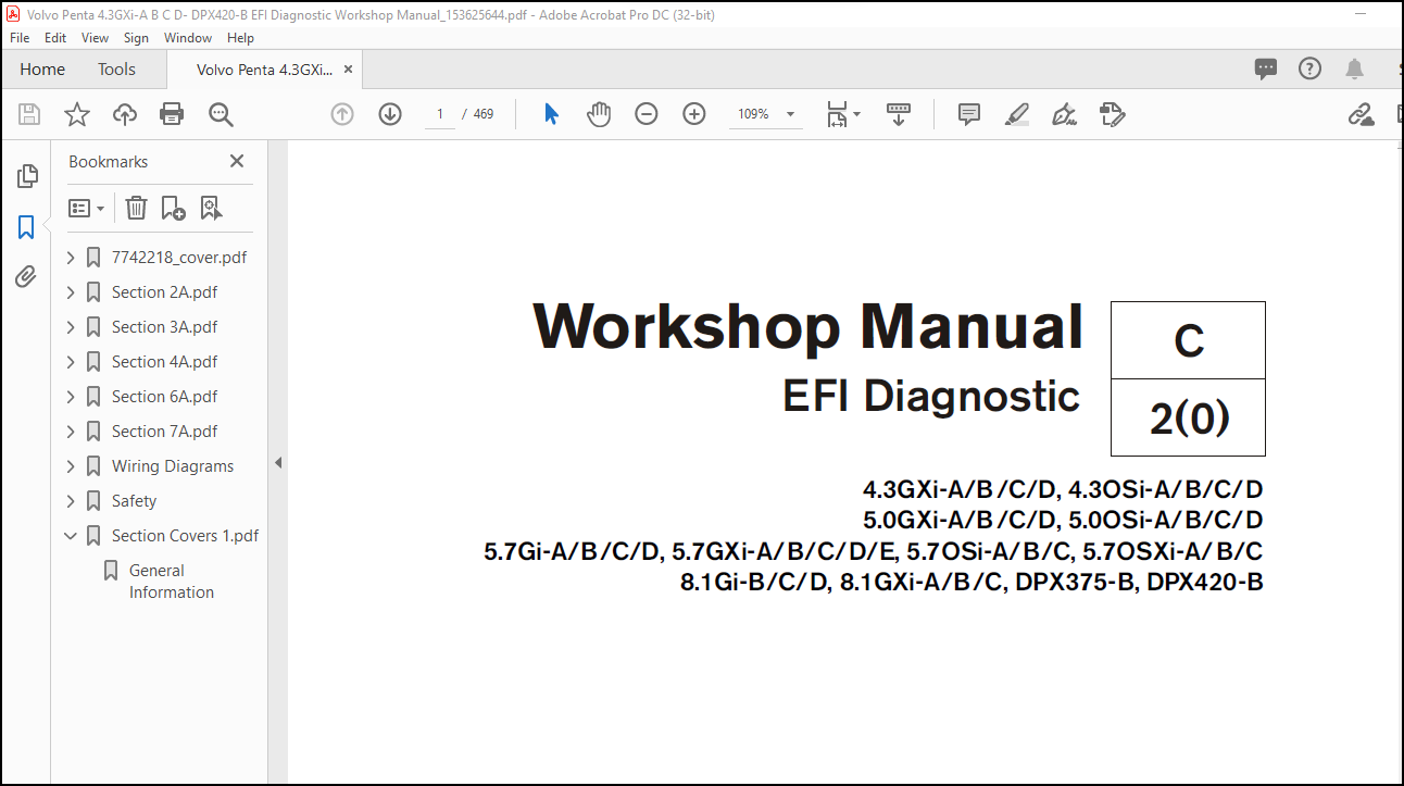
Volvo Penta 4.3GXi-A B C D- DPX420-B EFI Diagnostic Workshop Manual_153625644 – PDF DOWNLOAD
Volvo Penta 4.3GXi-A B C D- DPX420-B EFI Diagnostic Workshop Manual_153625644 – PDF DOWNLOAD
FILE DETAILS:
Volvo Penta 4.3GXi-A B C D- DPX420-B EFI Diagnostic Workshop Manual_153625644 – PDF DOWNLOAD
Language : English
Pages : 469
Downloadable : Yes
File Type : PDF
Size: 19.1 MB
IMAGES PREVIEW OF THE MANUAL:
DESCRIPTION:
Volvo Penta 4.3GXi-A B C D- DPX420-B EFI Diagnostic Workshop Manual_153625644 – PDF DOWNLOAD
4.3GXi-A/B/C/D, 4.3OSi-A/B/C/D
5.0GXi-A/B/C/D, 5.0OSi-A/B/C/D
5.7Gi-A/B/C/D, 5.7GXi-A/B/C/D/E, 5.7OSi-A/B/C, 5.7OSXi-A/B/C
8.1Gi-B/C/D, 8.1GXi-A/B/C, DPX375-B, DPX420-B
General Description :
The Electronic Fuel Injection (EFI) system on 43GXi-A, 50GXI-A, 57Gi-A, and 57GXi-B are equipped with a Marine Electronic Fuel Injection generation 3 (MEFI 3) computer that provides the operator with state-of-the-art fuel delivery and spark control. Computers use voltage to send and receive information as described below.
Sensors and Voltage Signals :
Voltage is electrical pressure. Voltage does not flow through circuits; instead, voltage causes current. Current does the real work in electrical circuits. It is current, the flow of electrically charged particles, that energizes solenoids, closes relays and lights lamps. Besides causing currents in circuits, voltage can be used as a signal. Voltage signals can send information by changing levels, changing wave form (shape), or changing the speed at which the signal switches from one level to another. Computers use voltage signals to communicate with one another. The different sections inside computers also use voltage signals to talk to each other. There are two kinds of voltage signals, analog and digital. Both of these are used in computer systems.
TABLE OF CONTENTS:
Volvo Penta 4.3GXi-A B C D- DPX420-B EFI Diagnostic Workshop Manual_153625644 – PDF DOWNLOAD
7742218_cover.pdf………………………………………………………………. 0
Page 1…………………………………………………………………….. 1
Section 2A.pdf…………………………………………………………………. 0
Contents…………………………………………………………………… 32
………………………………………………………………………. 32
General Description ……………………………………………………. 33
Sensors and Voltage Signals ……………………………………………… 33
Engine Control Module (ECM) ……………………………………………… 34
ECM Function ………………………………………………………….. 34
Memory ……………………………………………………………….. 34
Speed Density System ……………………………………………………. 35
ECM Inputs / Sensor Descriptions …………………………………………. 35
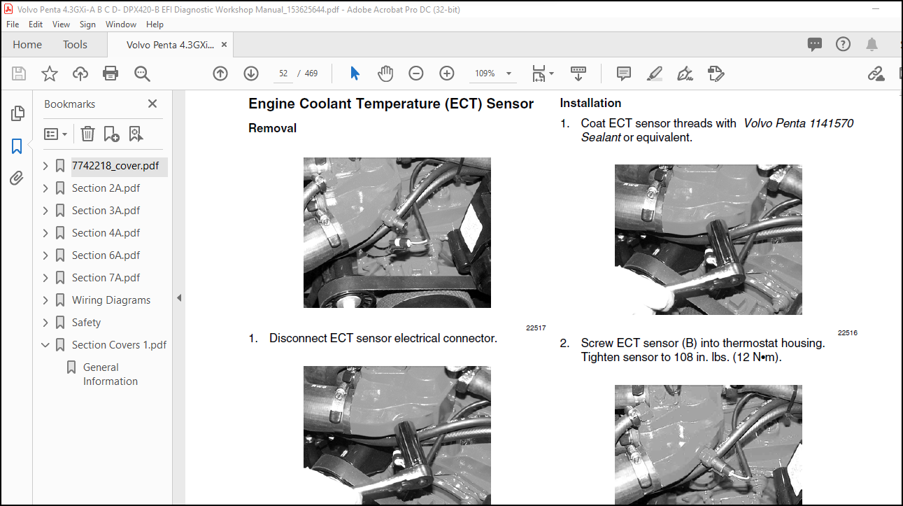
Engine Coolant Temperature (ECT) Sensor ………………………………….. 37
Manifold Absolute Pressure (MAP) Sensor ………………………………….. 37
Knock Sensor (KS) System ………………………………………………… 38
ENGINE PROTECTION MODE …………………………………………………. 39
Fuel System ……………………………………………………………. 40
Modes Of Operation ……………………………………………………… 40
Fuel Supply Components ………………………………………………….. 41
Fuel Pump Electrical Circuit …………………………………………….. 41
Fuel Injectors …………………………………………………………. 42
Pressure Regulator Assembly ……………………………………………… 42
Fuel System Operation ………………………………………………….. 44
Ignition System ………………………………………………………… 45
Ignition Coil ………………………………………………………….. 46
Ignition Control (IC) Module …………………………………………….. 46
Pole Piece and Coil Assembly ……………………………………………. 46
Engine Control Module (ECM) …………………………………………….. 47
Ignition Timing ……………………………………………………….. 47
Section 3A.pdf…………………………………………………………………. 0
Contents…………………………………………………………………… 50
………………………………………………………………………. 50
General Information ……………………………………………………. 51
Engine Control Module (ECM) …………………………………………….. 51
Engine Coolant Temperature (ECT) Sensor …………………………………… 52
Manifold Absolute Pressure (MAP) Sensor …………………………………… 53
Throttle Position (TP) Sensor ……………………………………………. 54
Idle Air Control (IAC) Valve …………………………………………….. 55
Knock Sensor (KS) ………………………………………………………. 56
Fuel System Component Replacement ………………………………………… 57
Fuel Control Service ……………………………………………………. 57
Fuel Pressure Relief Procedure …………………………………………… 58
Throttle Body Injector (TBI) Unit ……………………………………….. 59
Fuel Meter Cover Assembly ……………………………………………….. 61
Fuel Injector ………………………………………………………….. 63
Fuel Cell ……………………………………………………………… 66
Circuit Breaker ……………………………………………………….. 68
Relay Replacement ………………………………………………………. 68
Relay Ohmmeter Tests …………………………………………………… 69
Troubleshooting Electric Pump(s) ………………………………………… 70
Pressure Testing Fuel System ……………………………………………. 70
Troubleshooting Boat Fuel System …………………………………………. 71
Vacuum Testing Fuel System ……………………………………………… 71
Engine Fuel System Troubleshooting ………………………………………. 72
Engine Will Start When Primed – Will Not Continue to Run ……………………. 72
Engine Hard Starting, Cold ………………………………………………. 72
Engine Hard Starting, Hot ……………………………………………….. 72
Engine Runs Rough, Low Speed …………………………………………….. 72
Engine Runs Rough, High Speed ……………………………………………. 72
Engine Dies (On Initial Acceleration) or Has Acceleration Flat Spot ………….. 72
Engine Will Not Run at Recommended RPM ……………………………………. 72
Ignition System Description …………………………………………….. 73
Ignition Coil Test ……………………………………………………… 73
Pickup Coil Test ……………………………………………………….. 74
Ignition Module Test ……………………………………………………. 75
Inductor ………………………………………………………………. 75
Distributor ……………………………………………………………. 75
Setting Initial Timing …………………………………………………. 78
Setting Timing ………………………………………………………… 78
Ignition Coil Replacement ………………………………………………. 79
Ignition and Pickup Coils ……………………………………………….. 81
Specifications …………………………………………………………. 81
Ignition System Problems ……………………………………………….. 82
Torque Specifications …………………………………………………… 83
Section 4A.pdf…………………………………………………………………. 0
Contents…………………………………………………………………… 84
Important Preliminary Checks …………………………………………….. 87
Hard Start Symptom ……………………………………………………… 88
Surges Symptom …………………………………………………………. 89
Hesitation, Sag, or Stumble Symptom ………………………………………. 90
Detonation / Spark Knock Symptom …………………………………………. 91
Lack of Power, Sluggish, or Spongy Symptom ………………………………… 92
Cuts Out, Misses Symptom ………………………………………………… 93
Rough, Unstable or Incorrect Idle and Stalling Symptom ……………………… 94
Backfire (intake) Symptom ……………………………………………….. 95
Backfire (exhaust) Symptom ………………………………………………. 96
Dieseling, Run-On Symptom ……………………………………………….. 97
Poor Fuel Economy Symptom ……………………………………………….. 98
ECM J1 Connector and Symptoms Identification ………………………………. 99
ECM J1 Connector and Symptoms Identification (cont.) ………………………..100
ECM J2 Connector and Symptoms Identification ……………………………….101
Section 6A.pdf…………………………………………………………………. 0
Contents……………………………………………………………………130
Section 7A.pdf…………………………………………………………………. 0
Contents……………………………………………………………………154
DTC 14 – Engine Coolant Temperature (ECT) Sensor Low Temperature Indicated ……155
DTC 15 – Engine Coolant Temperature (ECT) Sensor – High Temperature Indicated ….157
DTC 21 – Throttle Position (TP) Sensor – Signal Voltage High …………………159
DTC 22 – Throttle Position (TP) Sensor – Signal Voltage Low ………………….161
DTC 33 – Manifold Absolute Pressure (MAP) Sensor – Signal Voltage High ………..163
DTC 34 – Manifold Absolute Pressure (MAP) Sensor – Signal Voltage Low …………165
DTC 41 – Ignition Control (IC) – Open IC Circuit ……………………………167
DTC 42 – Ignition Control (IC) – Grounded IC Circuit, Open or Grounded Bypass ….169
DTC 44 – Knock Sensor (KS) – System Inactive ……………………………….171
DTC 51 – ECM Calibration Memory Failure ……………………………………173
Engine Protection Mode Circuit …………………………………………..175
Wiring Diagrams…………………………………………………………………438
4.3GXi-A_5.0GXi-A_5.7Gi-A_5.7GXi-B…………………………………………….438
4.3GXi-B……………………………………………………………………440
4.3GXi-C/D………………………………………………………………….442
50GXi-B_57Gi-B_57GXi-C……………………………………………………….444
50GXi-C/D_57Gi-C/D_57GXi-D/E………………………………………………….446
81Gi-B, 81GXi-A……………………………………………………………..448
81Gi-C/D, 81GXi-B/C………………………………………………………….450
DPX375-B_DPX420-B.pdf………………………………………………………..452
Safety…………………………………………………………………………454
Part A……………………………………………………………………..455
Part B……………………………………………………………………..464
Section Covers 1.pdf……………………………………………………………. 0
General Information ………………………………………………………… 8
More products