$34
Volvo Penta 4.3GXi-A B C D- DPX420-B EFI Diagnostic Workshop Manual_263121146 – PDF DOWNLOAD
olvo Penta 4.3GXi-A B C D- DPX420-B EFI Diagnostic Workshop Manual_263121146 – PDF DOWNLOAD
FILE DETAILS:
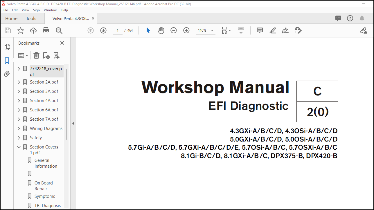
Volvo Penta 4.3GXi-A/B/C/D, 4.3OSi-A/B/C/D 5.0GXi-A/B/C/D, 5.0OSi-A/B/C/D 5.7Gi-A/B/C/D, 5.7GXi-A/B/C/D/E, 5.7OSi-A/B/C, 5.7OSXi-A/B/C 8.1Gi-B/C/D, 8.1GXi-A/B/C, DPX375-B, DPX420-B EFI Diagnostic Workshop Manual_263121146 – PDF DOWNLOAD
Language : English
Pages : 464
Downloadable : Yes
File Type : PDF
Size: 41.4 MB
IMAGES PREVIEW OF THE MANUAL:
DESCRIPTION:
Volvo Penta 4.3GXi-A/B/C/D, 4.3OSi-A/B/C/D 5.0GXi-A/B/C/D, 5.0OSi-A/B/C/D 5.7Gi-A/B/C/D, 5.7GXi-A/B/C/D/E, 5.7OSi-A/B/C, 5.7OSXi-A/B/C 8.1Gi-B/C/D, 8.1GXi-A/B/C, DPX375-B, DPX420-B EFI Diagnostic Workshop Manual_263121146 – PDF DOWNLOAD
4.3GXi-A/B/C/D, 4.3OSi-A/B/C/D
5.0GXi-A/B/C/D, 5.0OSi-A/B/C/D
5.7Gi-A/B/C/D, 5.7GXi-A/B/C/D/E, 5.7OSi-A/B/C, 5.7OSXi-A/B/C
8.1Gi-B/C/D, 8.1GXi-A/B/C, DPX375-B, DPX420-B
Service Precautions :
Tools Needed To Service The System Refer to Special Tools and Equipment List.The following requirements must be observed when working on MEFI equipped engines.1. Before removing any ECM system component, disconnect the negative battery cable.2. Never start the engine without the battery being solidly connected.3. Never separate the battery from the on-board electrical system while the engine is running.4. Never separate the battery feed wire from the charging system while the engine is running.5. When charging the battery, disconnect it from the vessel’s electrical system.6. Ensure that all cable harnesses are connected solid and the battery connections are thoroughly clean.7. Never connect or disconnect the wiring harness at the ECM when the ignition is switched “ON”.8. Before attempting any electric arc welding on the vessel, disconnect the battery leads and the ECM connector(s).9. When steam cleaning engines, do not direct the nozzle at any ECM system components. If this happens, corrosion of the terminals or damage of components can take place.10. Use only the test equipment specified in the diagnostic tables, since other test equipment may either give incorrect test results or damage good components.11. All measurements using a multimeter must use a digital meter with a rating of 10 megaohm input impedance.12. When a test light is specified, a “low-power” test light must be used. Do not use a high-wattage test light. While a particular brand of test light is not suggested, a simple test on any test light will ensure it to be safe for system circuit testing. Connect an accurate ammeter (such as the high-impedance digital multimeter) in series with the test light being tested, and power the test light ammeter circuit with the vessel battery.
TABLE OF CONTENTS:
Volvo Penta 4.3GXi-A/B/C/D, 4.3OSi-A/B/C/D 5.0GXi-A/B/C/D, 5.0OSi-A/B/C/D 5.7Gi-A/B/C/D, 5.7GXi-A/B/C/D/E, 5.7OSi-A/B/C, 5.7OSXi-A/B/C 8.1Gi-B/C/D, 8.1GXi-A/B/C, DPX375-B, DPX420-B EFI Diagnostic Workshop Manual_263121146 – PDF DOWNLOAD
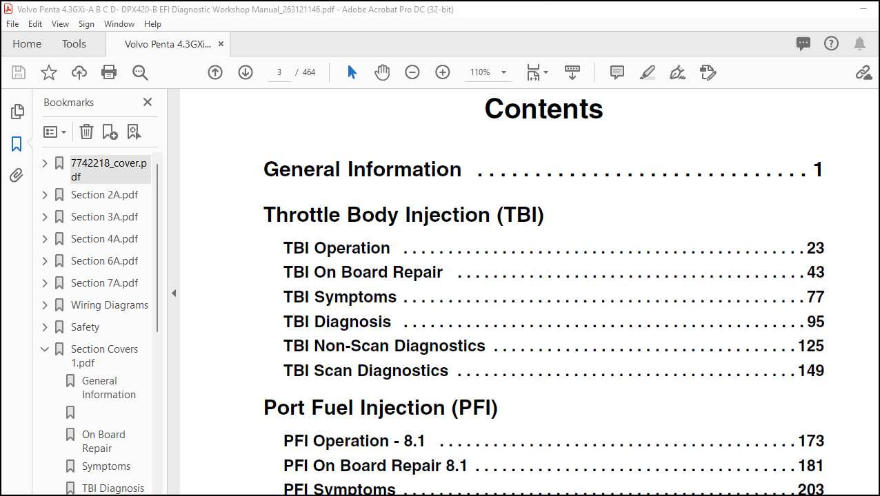
General Information . . . . . . . . . . . . . . . . . . . . . . . . . . . . . 1
Throttle Body Injection (TBI)
TBI Operation . . . . . . . . . . . . . . . . . . . . . . . . . . . . . . . . . . . . . . . . . . . . . 23
TBI On Board Repair . . . . . . . . . . . . . . . . . . . . . . . . . . . . . . . . . . . . . . . 43
TBI Symptoms . . . . . . . . . . . . . . . . . . . . . . . . . . . . . . . . . . . . . . . . . . . . . 77
TBI Diagnosis . . . . . . . . . . . . . . . . . . . . . . . . . . . . . . . . . . . . . . . . . . . . . 95
TBI Non-Scan Diagnostics . . . . . . . . . . . . . . . . . . . . . . . . . . . . . . . . . . 125
TBI Scan Diagnostics . . . . . . . . . . . . . . . . . . . . . . . . . . . . . . . . . . . . . . 149
Port Fuel Injection (PFI)
PFI Operation – 8.1 . . . . . . . . . . . . . . . . . . . . . . . . . . . . . . . . . . . . . . . . 173
PFI On Board Repair 8.1 . . . . . . . . . . . . . . . . . . . . . . . . . . . . . . . . . . . . 181
PFI Symptoms . . . . . . . . . . . . . . . . . . . . . . . . . . . . . . . . . . . . . . . . . . . . 203
PFI Diagnosis . . . . . . . . . . . . . . . . . . . . . . . . . . . . . . . . . . . . . . . . . . . . 219
PFI Scan Diagnostics 8.1 . . . . . . . . . . . . . . . . . . . . . . . . . . . . . . . . . . . 265
PFI Operation – 4.3, 5.0, 5.7 . . . . . . . . . . . . . . . . . . . . . . . . . . . . . . . . . 329
PFI On Board Repair 4.3, 5.0, 5.7 . . . . . . . . . . . . . . . . . . . . . . . . . . . . . 337
PFI Scan Diagnostics – 4.3, 5.0, 5.7 . . . . . . . . . . . . . . . . . . . . . . . . . . . 375
Wiring Diagrams
4.3GXi-A, 5.0GXi-A, 5.7Gi-A, 5.7GXi-A/B . . . . . . . . . . . . . . . . . . . . . . . . . . . . 435
4.3GXi-B . . . . . . . . . . . . . . . . . . . . . . . . . . . . . . . . . . . . . . . . . . . . . . . . . . . . . . 437
4.3GXi-C/D . . . . . . . . . . . . . . . . . . . . . . . . . . . . . . . . . . . . . . . . . . . . . . . . . . . . 439
5.0GXi-B, 5.7Gi-B, 5.7GXi-C . . . . . . . . . . . . . . . . . . . . . . . . . . . . . . . . . . . . . . 441
5.0GXi-C/D5.7Gi-C/D, 5.7GXi-D/E . . . . . . . . . . . . . . . . . . . . . . . . . . . . . . . . . . 443
8.1Gi-B, 8.1GXi-A . . . . . . . . . . . . . . . . . . . . . . . . . . . . . . . . . . . . . . . . . . . . . . . 445
8.1Gi-C/D, 8.1GXi-B/C . . . . . . . . . . . . . . . . . . . . . . . . . . . . . . . . . . . . . . . . . . . 447
DPX375, DPX420 . . . . . . . . . . . . . . . . . . . . . . . . . . . . . . . . . . . . . . . . . . . . . . . 449
Fues Box . . . . . . . . . . . . . . . . . . . . . . . . . . . . . . . . . . . . . . . . . . . . . . . . . . . . . . 451
Safety . . . . . . . . . . . . . . . . . . . . . . . . . . . . . . . . . . . . . . . . S1
More products