$34
Volvo Penta 4.3GXi-F(F)- 8.1OSi-C(F) EGC Diagnostics Workshop Manual_139179015 – PDF DOWNLOAD
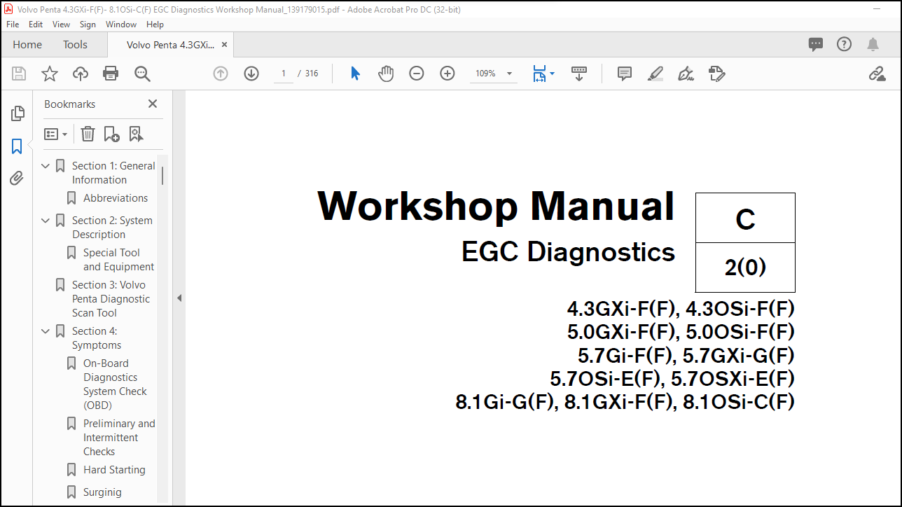
Volvo Penta 4.3GXi-F(F), 4.3OSi-F(F) 5.0GXi-F(F), 5.0OSi-F(F) 5.7Gi-F(F), 5.7GXi-G(F) 5.7OSi-E(F), 5.7OSXi-E(F) 8.1Gi-G(F), 8.1GXi-F(F), 8.1OSi-C(F) Diagnostics Workshop Manual_139179015 – PDF DOWNLOAD
FILE DETAILS:
Volvo Penta 4.3GXi-F(F), 4.3OSi-F(F) 5.0GXi-F(F), 5.0OSi-F(F) 5.7Gi-F(F), 5.7GXi-G(F) 5.7OSi-E(F), 5.7OSXi-E(F) 8.1Gi-G(F), 8.1GXi-F(F), 8.1OSi-C(F) Diagnostics Workshop Manual_139179015 – PDF DOWNLOAD
Language : English
Pages : 316
Downloadable : Yes
File Type : PDF
Size: 4.59 MB
IMAGES PREVIEW OF THE MANUAL:
DESCRIPTION:
Volvo Penta 4.3GXi-F(F), 4.3OSi-F(F) 5.0GXi-F(F), 5.0OSi-F(F) 5.7Gi-F(F), 5.7GXi-G(F) 5.7OSi-E(F), 5.7OSXi-E(F) 8.1Gi-G(F), 8.1GXi-F(F), 8.1OSi-C(F) Diagnostics Workshop Manual_139179015 – PDF DOWNLOAD
Good Service Practice Service required for the engine and sterndrive is generally one of three
kinds:
• Normal care and maintenance – which includes putting a new
engine and stern drive into operation, storing, lubrication, and
care under special operating conditions such as salt water and
cold weather.
• Operating malfunctions – due to improper engine or drive
mounting, propeller condition or size, boat condition, or the malfunction
of some part of the engine. This includes engine servicing
procedures to keep the engine in prime operating condition.
• Complete disassembly and overhaul – such as major service
or rebuilding a unit.
It is important to determine before disassembly just what the trouble is
and how to correct it quickly, with minimum expense to the owner.
When repairing an assembly, the most reliable way to ensure a good
job is to do a complete overhaul on that assembly, rather than just to
replace the bad part. Wear not readily apparent on other parts could
cause malfunction soon after the repair job. Repair kits and seal kits
contain all the parts needed to ensure a complete repair, to eliminate
guesswork, and to save time.
Repair time can also be minimized by the use of special tools. Volvo
Penta special tools are designed to perform service procedures
unique to the product that cannot be completed using tools from other
sources. They also speed repair work to help achieve service flat rate
times. In some cases, the use of substitute tools can damage the part.
Preparation for Service Proper preparation is extremely helpful for efficient service work. A
clean work area at the start of each job will minimize tools and parts
becoming misplaced. Clean an engine that is excessively dirty before
work starts. Cleaning will occasionally uncover trouble sources. Obtain
tools, instruments and parts needed for the job before work is started.
Interrupting a job to locate special tools or repair kits is a needless
delay.
Caution
TABLE OF CONTENTS:
Volvo Penta 4.3GXi-F(F), 4.3OSi-F(F) 5.0GXi-F(F), 5.0OSi-F(F) 5.7Gi-F(F), 5.7GXi-G(F) 5.7OSi-E(F), 5.7OSXi-E(F) 8.1Gi-G(F), 8.1GXi-F(F), 8.1OSi-C(F) Diagnostics Workshop Manual_139179015 – PDF DOWNLOAD
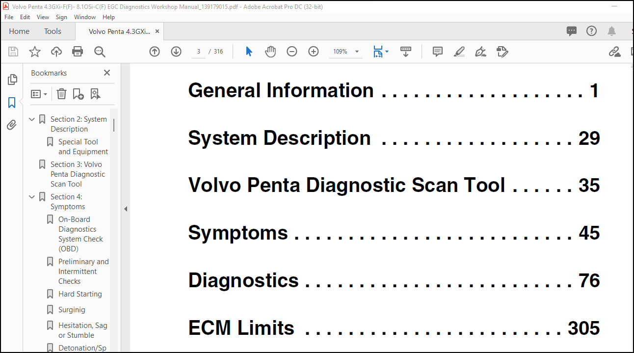
Section 1: General Information……………………………… 5
Abbreviations…………………………………………. 31
Section 2: System Description………………………………. 33
Special Tool and Equipment……………………………… 37
Section 3: Volvo Penta Diagnostic Scan Tool………………….. 39
Section 4: Symptoms……………………………………….. 49
On-Board Diagnostics System Check (OBD)………………….. 50
Preliminary and Intermittent Checks……………………… 52
Hard Starting…………………………………………. 54
Surginig……………………………………………… 56
Hesitation, Sag or Stumble……………………………… 57
Detonation/Spark Knock…………………………………. 58
Lack of Power, Sluggish or Spongy……………………….. 59
Cuts Out, Misses………………………………………. 61
Rough, Unstable, or Incorrect Idle; Stalling……………… 63
Backfire……………………………………………… 65
Dieseling, Run-On……………………………………… 67
Poor Fuel Economy……………………………………… 68
ECM Connector Identification……………………………. 70
Section 5: Diagnostics…………………………………….. 80
DTC 0016 – Never Crank Synced At Start…………………… 83
DTC 0107 – MAP Low Voltage……………………………… 85
DTC 0108 – MAP High Pressure……………………………. 87
DTC 0111 – IAT Higher Than Expected 1……………………. 89
DTC 0112 – IAT Low Voltage……………………………… 91
DTC 0113 – IAT High Voltage…………………………….. 93
DTC 0116 – ECT Higher Than Expected 1……………………. 95
DTC 0117 – ECT Low Voltage……………………………… 97
DTC 0118 – ECT High Voltage…………………………….. 99
DTC 0121 – TPS 1 Lower Than TPS 2………………………..101
DTC 0122 – TPS 1 Signal Voltage Low (ETC)…………………103
DTC 0122 – TPS Signal Voltage Low (IAC)…………………..105
DTC 0123 – TPS 1 Signal Voltage High (ETC)………………..107
DTC 0123 – TPS Signal Voltage High (IAC)………………….109
DTC 0127 – IAT Higher Than Expected 2…………………….111
DTC 0129 – BP Low Pressure………………………………113
DTC 0217 – ECT Higher Than Expected 2…………………….115
DTC 0219 – Maximum Governor Speed Override………………..117
DTC 0221 – TPS 1 Higher Than TPS 2……………………….119
DTC 0222 – TPS 2 Low Voltage…………………………….121
DTC 0223 – TPS 2 High Voltage……………………………123
DTC 0261 – Injector Driver 1 Open………………………..125
DTC 0264 – Injector Driver 2 Open………………………..127
DTC 0265 – Injector Driver 2 Shorted……………………..129
DTC 0267 – Injector Driver 3 Open………………………..131
DTC 0268 – Injector Driver 3 Shorted……………………..133
DTC 0270 – Injector Driver 4 Open………………………..135
DTC 0271 – Injector Driver 4 Shorted……………………..137
DTC 0273 – Injector Driver 5 Open………………………..139
DTC 0274 – Injector Driver 5 Shorted……………………..141
DTC 0276 – Injector Driver 6 Open………………………..143
DTC 0277 – Injector Driver 6 Shorted……………………..145
DTC 0279 – Injector Driver 7 Open………………………..147
DTC 0280 – Injector Driver 7 Shorted……………………..149
DTC 0282 – Injector Driver 8 Open………………………..151
DTC 0283 – Injector Driver 8 Shorted……………………..153
DTC 0326 – Knock 1 Excessive Signal………………………155
DTC 0327 – Knock Sensor 1 Open…………………………..157
DTC 0331 – Knock 2 Excessive Signal………………………159
DTC 0332 – Knock Sensor 2 Open…………………………..161
DTC 0336 – Crank Sync Noise……………………………..163
DTC 0337 – Crankshaft Sensor Loss………………………..165
DTC 0341 – Camshaft Sensor Noise…………………………167
DTC 0342 – Camshaft Sensor Loss………………………….169
DTC 0508 – IAC Ground Short……………………………..171
DTC 0509 – IAC Coil Open/Short…………………………..173
DTC 0522 – Oil Pressure Sender Low Voltage………………..175
DTC 0523 – Oil Pressure Sender High Voltage……………….177
DTC 0524 – Low Oil Pressure……………………………..179
DTC 0562 – System Voltage Low……………………………181
DTC 0563 – System Voltage High…………………………..183
DTC 0601 – Flash Checksum Invalid………………………..185
DTC 0604 – RAM Failure………………………………….187
DTC 0606 – COP Failure………………………………….189
DTC 0627 – Fuel Pump Relay Coil Open……………………..191
DTC 0628 – Fuel Pump Relay Control Ground Short……………193
DTC 0629 – Fuel Pump Relay Coil Short to Power…………….195
DTC 0642 – V REF #1 Voltage Low (ETC)…………………….197
DTC 0642 – V REF Voltage Low (IAC)……………………….199
DTC 0642 – V REF Voltage Low (IAC)……………………….201
DTC 0643 – V REF #1 Voltage High (ETC)……………………203
DTC 0643 – V REF Voltage High (IAC)………………………205
DTC 0652 – V REF #2 Voltage Low………………………….207
DTC 0653 – V REF #2 Voltage High…………………………209
DTC 0685 – Ignition Relay Coil Open………………………211
DTC 0686 – Ignition Relay Control Ground Short…………….213
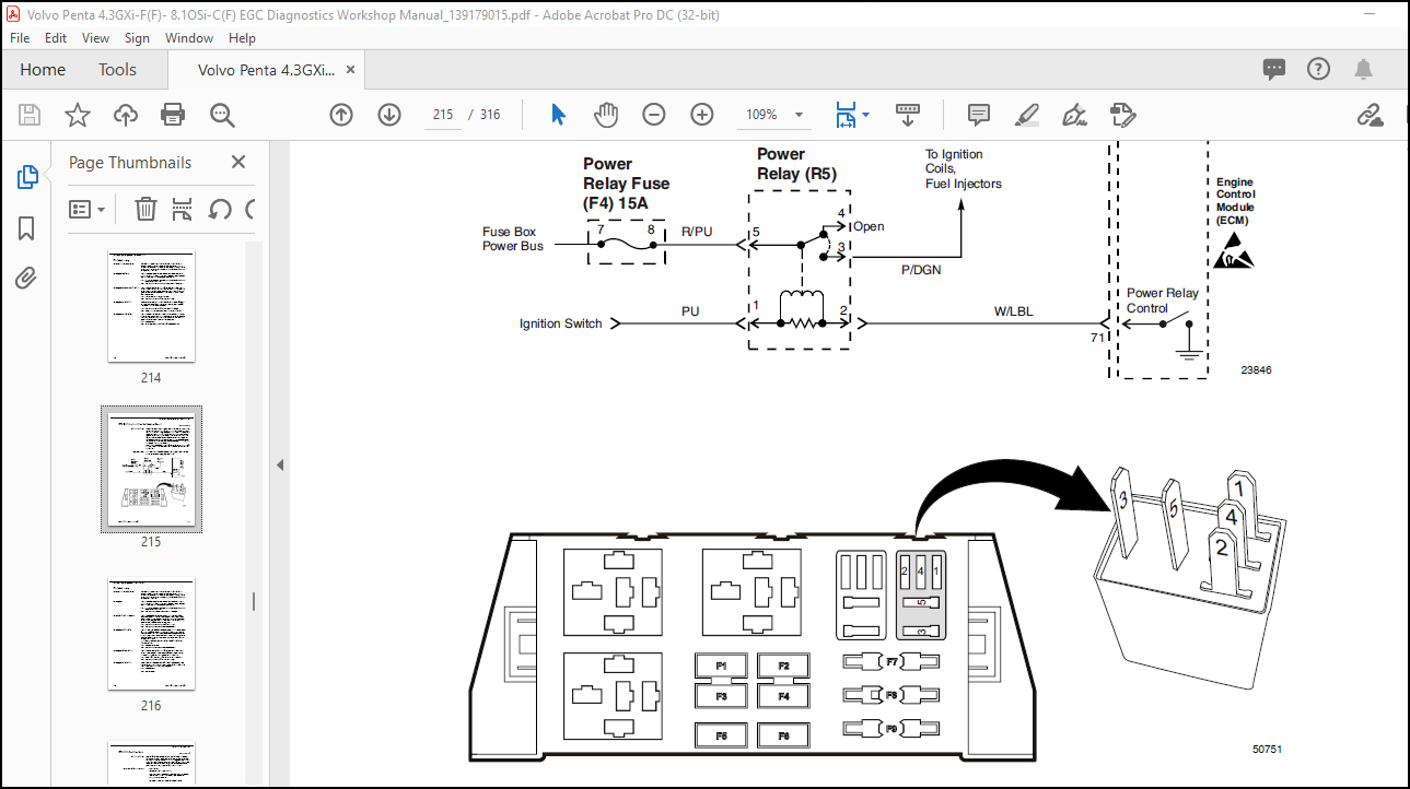
DTC 0687 – Ignition Relay Coil Short to Power……………..215
DTC 1111 – Fuel Rev Limit……………………………….217
DTC 1112 – Spark Rev Limit………………………………219
DTC 1121 – TCP 1/2 Simultaneous Voltages Out-of-Range………221
DTC 1122 – TCP 1 and TCP 2 Do Not Match or IVS…………….223
DTC 1511 – Trim Sender Voltage High (2-Wire)………………225
DTC 1511 – Trim Sender Voltage High (3-Wire)………………227
DTC 1611 – 5V 1/2 Simultaneous Out-of-Range……………….229
DTC 1612 – RTI 1 Loss…………………………………..231
DTC 1613 – RTI 2 Loss…………………………………..233
DTC 1614 – RTI 3 Loss…………………………………..235
DTC 1615 – A/D Loss…………………………………….237
DTC 1616 – Invalid Interrupt…………………………….239
DTC 1628 – CAN Address Conflict Failure…………………..241
DTC 1631 – Water Temperature Gauge Open/Short to Ground…….243
DTC 1631 – Water Temperature Gauge Open/Short to Ground…….245
DTC 1632 – Water Temperature Gauge Short to Power………….247
DTC 1633 – Oil Pressure Gauge Open / Short to Ground……….249
DTC 1634 – Oil Pressure Gauge Short to Power………………251
DTC 1635 – Trim Position Gauge Open / Short to Ground………253
DTC 1636 – Trim Position Gauge Short to Power……………..255
DTC 1641 – Buzzer Control Ground Short……………………257
DTC 1642 – Buzzer Open………………………………….259
DTC 1643 – Buzzer Control Short to Power………………….261
DTC 2111 – Throttle Unable To Close………………………263
DTC 2112 – Throttle Unable To Open……………………….265
DTC 2115 – TCP 1 Higher Than IVS limit……………………267
DTC 2116 – TCP 2 Higher Than IVS Limit……………………269
DTC 2120 – TCP 1 Invalid Voltage, TCP 2 Disagrees with IVS….271
DTC 2121 – TCP 1 Lower Than TCP 2………………………..273
DTC 2122 – TCP 1 High Voltage……………………………275
DTC 2123 – TCP 1 Low Voltage…………………………….277
DTC 2125 – TCP 2 Invalid Voltage, TCP 1 Disagrees with IVS….280
DTC 2126 – TCP 1 Higher Than TCP 2……………………….282
DTC 2127 – TCP 2 Low Voltage…………………………….284
DTC 2128 – TCP 2 High Voltage……………………………287
DTC 2130 – IVS Stuck At-Idle TCP 1/2 Match………………..289
DTC 2131 – IVS Stuck Off-Idle……………………………291
DTC 2135 – TPS 1/2 Simultaneous Voltages Out-of-Range………293
DTC 2139 – TCP 1 Lower Than IVS limit…………………….295
DTC 2140 – TCP 2 Lower Than IVS Limit…………………….297
DTC 2229 – BP High Pressure……………………………..299
DTC 2428 – EGT Temperature High………………………….301
DTC 2618 – Tachometer Output Ground Short…………………303
DTC 2619 – Tachometer Output Short to Power……………….305
Section 6: ECM Limits………………………………………309
Vodia Index by Number………………………………………314
More products