$34
Volvo Penta D4,D6, D9, D12, D16 Electronic Vessel Control Installation Manual_312955613 PDF
Volvo Penta D4,D6, D9, D12, D16 Electronic Vessel Control Installation Manual_312955613 – PDF DOWNLOAD
FILE DETAILS:
Volvo Penta D4,D6, D9, D12, D16 Electronic Vessel Control Installation Manual_312955613 – PDF DOWNLOAD
Language : English
Pages : 138
Downloadable : Yes
File Type : PDF
Size: 3.53 MB
IMAGES PREVIEW OF THE MANUAL:
DESCRIPTION:
Volvo Penta D4,D6, D9, D12, D16 Electronic Vessel Control Installation Manual_312955613 – PDF DOWNLOAD
Safety precautions:Introduction :This Installation Manual contains the information you will need to install and test the Electronic Vessel Control (EVC) system. Read this Installation Manual carefully before installation. Incorrect installation may result in personal injury or damage to property or the engine itself. If you do not understand or are uncertain about any operation or information in this Installation Manual, please contact the Volvo Penta organization.Installation:This Installation Manual is intended for professional use only. The Manual must be used in conjunction with the relevant Engine Operator’s Manual. Volvo Penta will not assume any liability for damage to materials or personal injury, which may result if the installation instructions are not followed or if the work is carried out by non-professional personnel. The installer is responsible for ensuring that the system operates in accordance with this Installation Manual.Work procedures :These instructions are for use by suitably qualified personnel, referred to as the installer in these instructions. Refer to the specific Engine Operator’s manual for relevant information where necessary, especially regarding safety and engine operation. The work must be done at Volvo Penta’s service workshops, boat builders or other authorised and suitably equipped workshops with personnel who have the appropriate qualifications and experience.
TABLE OF CONTENTS:
Volvo Penta D4,D6, D9, D12, D16 Electronic Vessel Control Installation Manual_312955613 – PDF DOWNLOAD
Safety precautions……………………………………….. 5
General information……………………………………… 7
Engine monitoring and the EVC system………… 10
Engine monitoring system………………………….. 10
The EVC-C system……………………………………. 11
Installation tools and literature……………………… 13
Other special equipment……………………………….. 14
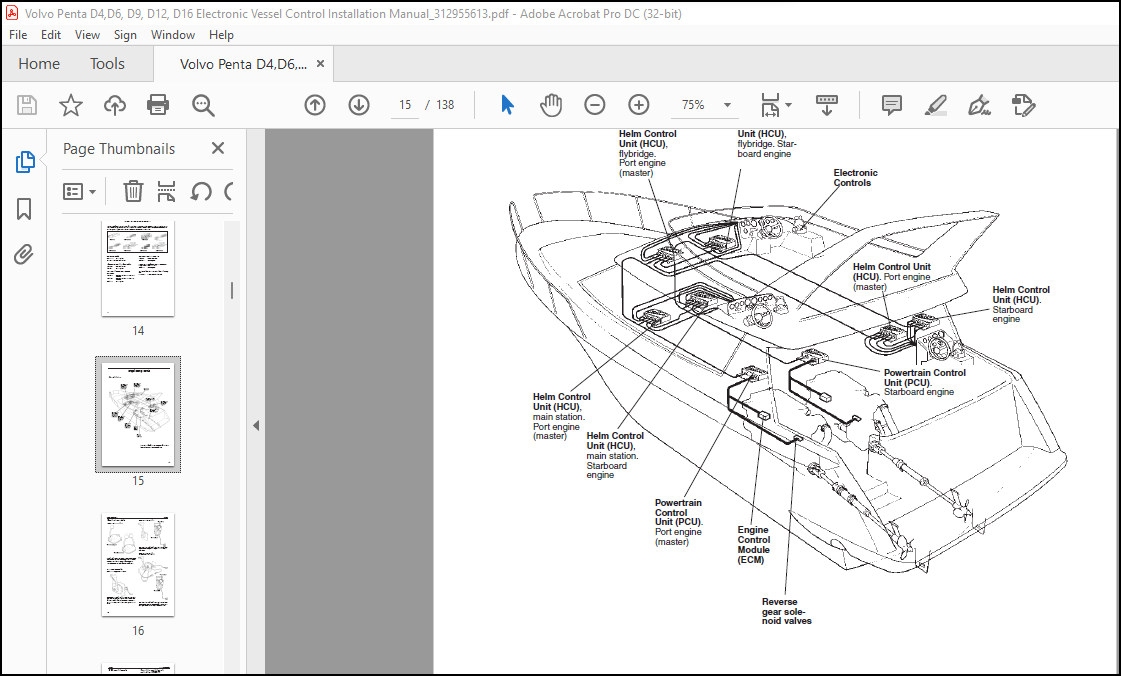
Major components………………………………………… 15
General view…………………………………………….. 15
Installation procedure, general……………………… 28
Cable routing……………………………………………. 29
Marking and color coding of cables……………… 32
Building an EVC network……………………………. 33
Identification of the PCU and the HCU…………. 34
Installation procedure, engine room………………. 35
Location and mounting of the PCU and HCU… 35
Engine–PCU cable, stern drive…………………… 36
Engine–PCU cable, Inboard engine…………….. 36
Transmission cables………………………………….. 37
Checking rotation of propeller, D4/D6………….. 38
Checking rotation of propeller, D9/D12/D16….. 39
Volvo Penta Lowspeed and Trolling……………… 42
PCU, installation ………………………………………. 43
Fuel and fresh water level senders ……………… 43
Rudder indicator ………………………………………. 46
Standard bus cable PCU–HCU ………………….. 45
HCU, installation……………………………………….. 47
Powertrim system, D4/D6 stern drive…………… 48
Gear shift actuator, D4/D6 stern drive………….. 48
Installation procedure, helm………………………….. 49
Y-connector……………………………………………… 49
Key switch and relay………………………………….. 49
Start/stop panel………………………………………… 50
EVC control panel…………………………………….. 52
Powertrim panel……………………………………….. 54
Relay for external accessories……………………. 55
Instruments………………………………………………. 57
Instrument, panels and auxiliary cable…………. 59
Buzzer…………………………………………………….. 60
Auxilliary dimmer unit (ADU)………………………. 61
Synchronizing cable, twin installtions…………… 62
EVC system display…………………………………… 63
NMEA 0183 interface………………………………… 68
NMEA 2000 interface………………………………… 69
Multisensor………………………………………………. 71
Controls, electronic……………………………………. 72
Adapter for mechanical controls………………….. 75
Controls, mechanical…………………………………. 76
Interface 4–20 mA…………………………………….. 79
EVC control panels……………………………………….. 82
Calibration and settings………………………………… 83
General……………………………………………………. 83
Calibration mode………………………………………. 84
Auto configuration……………………………………… 84
EVC control lever combinations .
Calibration summary…………………………………. 86
Lever calibration……………………………………….. 88
Select language and units………………………….. 91
Powertrim calibration…………………………………. 92
Powertrim Assistance, PTA………………………… 93
Trolling calibration……………………………………… 94
Slip calibration………………………………………….. 95
Idling speed calibration………………………………. 96
OEM-mode………………………………………………. 97
Fuel tank settings……………………………………… 97
Fuel tank calibration………………………………….. 98
Multisensor calibration……………………………….. 100
EVC system display…………………………………… 102
Diagnostic function………………………………………. 107
Fault register………………………………………………… 109
Parameter settings……………………………………….. 117
Starting the engine……………………………………….. 119
Wiring color and pin-out schematics…………….. 123
Templates for controls and panels………………… 125
References to Service bulletins…………………….. 136
More products