$33
Volvo Penta D9A2A MP, D9A2A MH, D12D-B MP Group 30 Electrical System Workshop Manual_87094076 – PDF
Volvo Penta D9A2A MP, D9A2A MH, D12D-B MP Group 30 Electrical System Workshop Manual_87094076 – PDF
FILE DETAILS:
Volvo Penta D9A2A MP, D9A2A MH, D12D-B MP Group 30 Electrical System Workshop Manual_87094076 – PDF
Language : English
Pages : 216
Downloadable : Yes
File Type : PDF
Size: 1.2 MB
IMAGES PREVIEW OF THE MANUAL:

DESCRIPTION:
Volvo Penta D9A2A MP, D9A2A MH, D12D-B MP Group 30 Electrical System Workshop Manual_87094076 – PDF
General information:
About this Workshop Manual:
This Workshop Manual contains descriptions and instructions for the repair of marine diesel engines D9A2A MP, D9A2A MH and D12D-B MP. The engine designation and number are noted on the number plate and engine decal. The engine designation and number must always be given in all correspondence about any product.
- The Workshop Manual is produced primarily for the use of Volvo Penta workshops and service technicians. This assumes that people who use the Manual have basic knowledge of marine drive systems and can do the tasks of a mechanical or electrical nature associated with the trade.
- Volvo Penta constantly improves its products, so we reserve the right to make modifications without prior notification. All information in this manual is based on product data which was available up to the date on which the manual was printed. Any material changes introduced into the product or service methods after this date are notified by means of Service Bulletins.
Spare parts:
Spare parts for electrical- and fuel systems are subject to various national safety requirements, such as U.S. Coast Guard Safety Regulations. Volvo Penta Original Spare Parts meet these specifications. Any damage, occasioned by use of non–original Volvo Penta spares for the product, will be not be compensated by the warranty offered by Volvo Penta.
TABLE OF CONTENTS:
Volvo Penta D9A2A MP, D9A2A MH, D12D-B MP Group 30 Electrical System Workshop Manual_87094076 – PDF
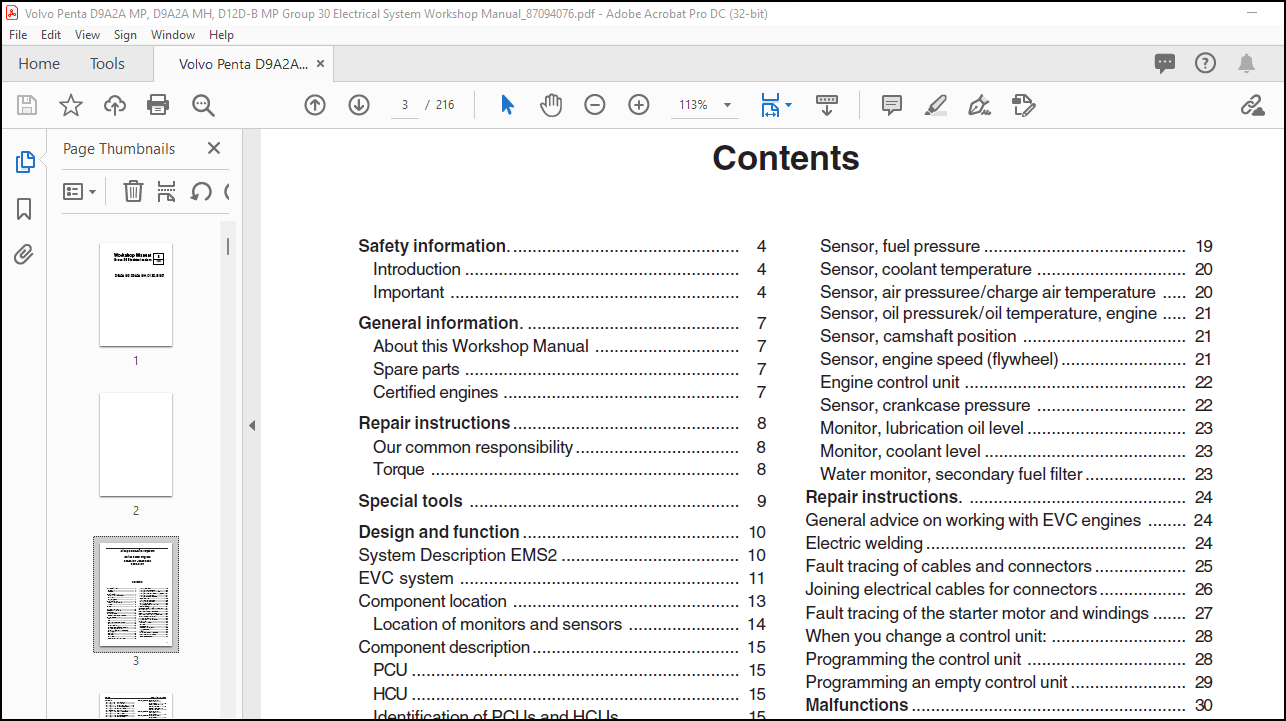
Safety information 4
Introduction 4
Important 4
General information 7
About this Workshop Manual 7
Spare parts 7
Certified engines 7
Repair instructions 8
Our common responsibility 8
Torque 8
Special tools 9
Design and function 10
System Description EMS2 10
EVC system 11
Component location 13
Location of monitors and sensors 14
Component description 15
PCU 15
HCU 15
Identification of PCUs and HCUs 15
Controls 16
AUX stop button 16
Solenoid valves, forwardsm– reverse 17
Solenoid valve, low speed 17
Sensor, oil pressuree/oil temperature,
reversing gear 17
Starter motor 18
Alternator 18
Unit injector 19
Piston cooling monitor (D12-800) 19
Sensor, fuel pressure 19
Sensor, coolant temperature 20
Sensor, air pressuree/charge air temperature 20
Sensor, oil pressurek/oil temperature, engine 21
Sensor, camshaft position 21
Sensor, engine speed (flywheel) 21
Engine control unit 22
Sensor, crankcase pressure 22
Monitor, lubrication oil level 23
Monitor, coolant level 23
Water monitor, secondary fuel filter 23
Repair instructions 24
General advice on working with EVC engines 24
Electric welding 24
Fault tracing of cables and connectors 25
Joining electrical cables for connectors 26
Fault tracing of the starter motor and windings 27
When you change a control unit: 28
Programming the control unit 28
Programming an empty control unit 29
Malfunctions 30
Fault code information 30
FMI table 30
General advice 31
System introduction, EVC 32
Starting sequence 32
Network 33
Manual fault tracing in bus cables 33
Fault tracing the EVC system 34
Checking the instruments 35
Fault codes
MID 128, PID 94 Fuel pressure 36
MID 128, PID 97 Water in fuel 41
MID 128, PID 98 Oil level (engine) 44
MID 128, PID 100 Oil pressure, (engine) 47
MID 128, PID 105 Charge air temperature 52
MID 128, PID 106 Charge air pressure 56
MID 128, PID 110 Coolant temperature 61
MID 128, PID 111 Coolant level 65
MID 128, PID 153 Crankcase pressure 68
MID 128, PID 158 Battery voltage 73
MID 128, PID 163 Selected gear 74
MID 128, PID 175 Oil temperature, engine 75
MID 128, PPID 3 Starting relay fault 79
MID 128, PPID 6 External stopping relay 82
MID 128, PPID 8 Piston cooling pressure
(D12-800) 84
MID 128, PPID 98 Engine synchronisation 86
MID 128, PPID 132 Throttle position 87
MID 128, SID 1-6 Unit injectors 1-6 88
MID 128, SID 21 Sensor for camshaft
position (speed sensor,
camshaft) 94
MID 128, SID 22 Speed sensor (flywheel) 97
MID 128, SID 32 Waste gate (D12-800) 100
MID 128, SID 232 5 Volt DC Supply current 102
MID 128, SID 240 Program memory fault 104
MID 128, SID 254 Engine control unit 105
MID 128, PSID 216 Communication fault
J1939 106
MID 128, SID 231 Communication fault
J1939 108
MID 164, PPID 390 Voltagesupplyfault
control 1 in relation to
potentiometer 110
Checking potentiometer in
electronic controls 112
Changing potentiometer in
electronic controls 114
MID 164, PPID 391 Voltagesupplyfault
control 2 in relation to
potentiometer 115
MID 164, PPID 392 Voltagesupply control
potentiometer 117
MID 164, PPID 393 /
MID 187, PPID 393 Power supply
data bus 119
MID 164, PPID 394 Power supply
starter switch 121
Checking the starter
switch 122
MID 164, PPID 397 Main panel lost
communication 123
MID 164, SID 226 Mismatch between
neutral switch and
throttle control 125
MID 164, SID 231 Communication fault,
synchronization bus 127
MID 164, SID 240 /
MID 187, SID 240 Program memory fault 129
MID 164, SID 250 SAE J1708 / J1587
data line 13
MID 164, SID 253 /
MID 187, SID 253 Node configuration fault /
memory fault, calibration 131
MID 164, SID 254 /
MID 187, SID 254 Internal CPU fault 133
MID 164, PSID 95 Control detection 134
MID 164, PSID 96 Too short lever movement
calibrated 136
MID 164, PSID 97 Control calibration
procedure 137
MID 164, PSID 98 Control(s) is/are not
calibrated 138
MID 164, PSID 105 Activation button,
control station 139
MID 164, PSID 106 Start 141
MID 164, PSID 107 Stop 143
MID 164, PSID 218 Communication fault,
data bus, passive /
active control station 145
MID 164, PSID 226 HCU communication fault
to another control station 147
MID 164, PSID 231 Incompatible EVC nodes 149
3
Group 30: Electrical system Contents
MID 187, PID 96 Fuel level 150
MID 187, PID 127 Oil pressure
(reversing gear) 152
MID 187, PID 177 Oil temperature
(reversing gear) 155
MID 187, PID 191 Low speed with feedback 158
MID 187, PPID 400 Power supply, reversing
gear sensor 160
MID 187, SID 231 J1939 Communications
warning / fault 162
MID 187, SID 250 J1587 / J1708 Communication
warning / fault 164
MID 187, PSID 10 Incompatible engine type 166
MIS 187, PSID 16 /
MID 164, PSID 94 Incompatible software,
EVC 167
MID 187, PSID 17 /
MID 164, PSID 99 Configuration fault, data
bus network 168
MID 187, PSID 18 Data bus supply voltage 170
MID 187, PSID 20 Primary solenoid valve 172
MID 187, PSID 22 Secondary solenoid valve 176
MID 187, PSID 32 Data bus, communication
fault with active control
station 178
MID 187, PSID 200 No data on the motor bus 180
MID 187, PSID 226 Data bus, communication
fault with passive /
active helm station 182
MID 187, PSID 231 Incompatible EVC nodes 184
MID 187, PSID 232 /
MID 164, PSID 232 Communication warning
data bus 185
© 2005 AB VOLVO PENTA
We reserve the right to make modifications without prior notice Printed on environmentally compatible paper
Wiring diagram 188
D9-500, D9-575 188
D12-800 190
Twin engine installation 192
Controls 193
Pin configuration, PCU 194
Pin configuration, HCU 195
Automatic configuration and calibration
before starting 196
Calibration procedure, example of workflow 196
Combinations of control levers for EVC
Overview, calibration 197
Preparations 198
Auto configuration 198
Calibration Electronic single lever control 199
Calibration Alternative control station
(without starter switch) 200
Calibration Idling 201
Calibration Mechanical twin lever control,
single / twin Electronically shifted
reversing gear 202
Calibration Mechanical twin lever control,
single / twin Mechanically shifted
reversing gear 203
Checking propeller rotation 204
References to Service Bulletins 205
Technical data 206
Index 208
More products