$33
Volvo Penta TAD650VE- TAD760VE, TAD734GE Group 30 Workshop Manual_304495118 – PDF DOWNLOAD
Volvo Penta TAD650VE- TAD760VE, TAD734GE Group 30 Workshop Manual_304495118 – PDF DOWNLOAD
FILE DETAILS:
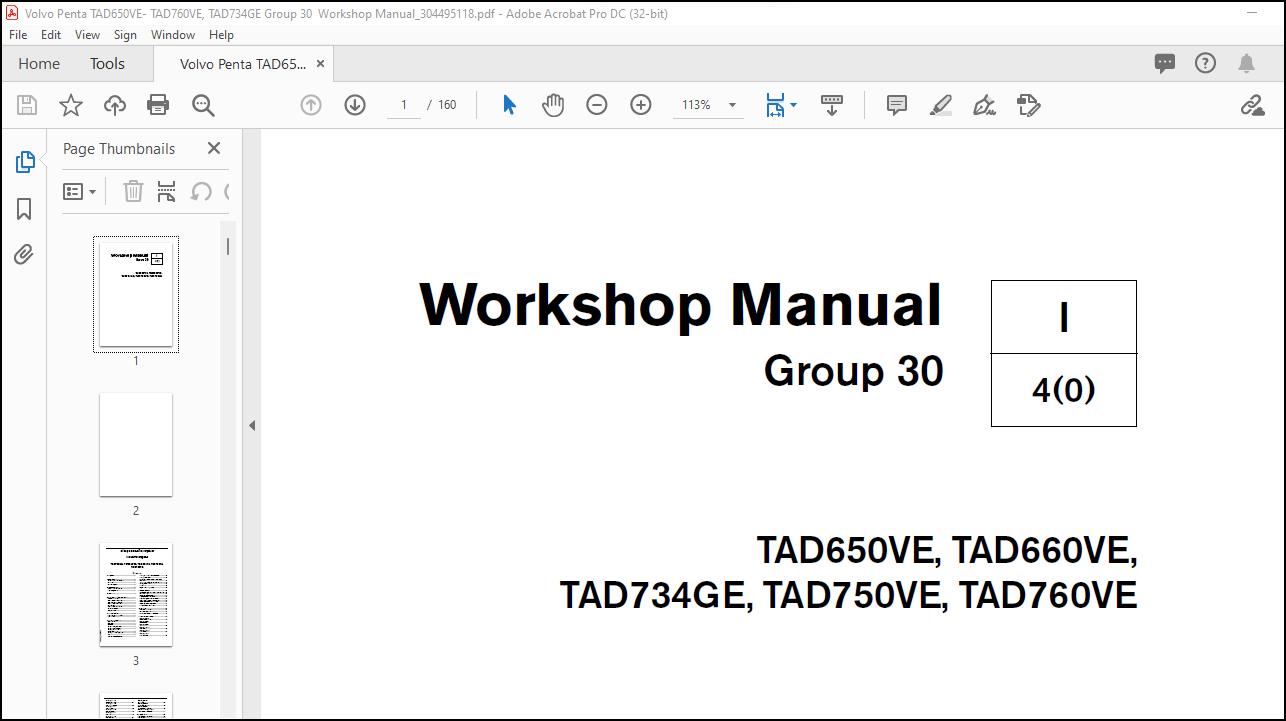
Volvo Penta TAD650VE, TAD660VE, TAD734GE, TAD750VE, TAD760VE Group 30 Workshop Manual_304495118 – PDF DOWNLOAD
Language : English
Pages : 160
Downloadable : Yes
File Type : PDF
Size: 2.35 MB
IMAGES PREVIEW OF THE MANUAL:
DESCRIPTION:
Volvo Penta TAD650VE, TAD660VE, TAD734GE, TAD750VE, TAD760VE Group 30 Workshop Manual_304495118 – PDF DOWNLOAD
TAD650VE, TAD660VE,
TAD734GE, TAD750VE, TAD760VE
General information:
About this Workshop Manual:
This workshop manual contains descriptions and repair instructions for the standard versions of the TAD734GE, TAD650VE, TAD660VE, TAD750 and TAD760VE engines. The workshop manual can illustrate tasks done on any of the engines noted above. This means that the illustrations and photographs which clarify certain details might not correspond with other engines in some cases. Repair methods are similar in all important respects, however.
- If this is not the case, this is noted. Important differences are noted separately. The engine designation and number are noted on the number plate and engine decal. The engine designation and number must always be given in all correspondence about any product.
- The workshop manual is produced primarily for the use of Volvo Penta workshops and service technicians. For this reason the manual presupposes a certain basic knowledge and that the user can carry out the mechanical/electrical work described to a general standard of engineering competence.
- Volvo Penta constantly improves its products, so we reserve the right to make modifications without prior notification. All information in this manual is based on product data which was available up to the date on which the manual was printed. Any material changes introduced into the product or service methods after this date are notified by means of Service Bulletins.
Spare parts:
Spare parts for electrical and fuel systems are subject to various national safety requirements. Volvo Penta Original Spare Parts meet these specifications. Any kind of damage whatsoever, occasioned by use of non-original Volvo Penta spares for the product in question, will not be compensated by the warranty offered by Volvo Penta.
TABLE OF CONTENTS:
Volvo Penta TAD650VE, TAD660VE, TAD734GE, TAD750VE, TAD760VE Group 30 Workshop Manual_304495118 – PDF DOWNLOAD
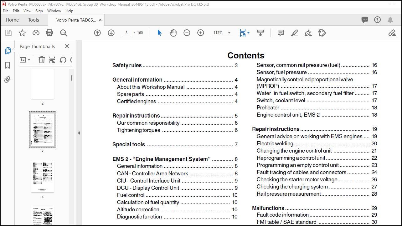
Safety rules …………………………………………………… 3
General information ………………………………………. 4
About this Workshop Manual …………………………. 4
Spare parts …………………………………………………. 4
Certified engines ………………………………………….. 4
Repair instructions ………………………………………… 5
Our common responsibility …………………………….. 6
Tightening torques ……………………………………….. 6
Special tools ………………………………………………… 7
EMS 2 – “Engine Management System” ………….. 8
General information ………………………………………. 8
CAN – Controller Area Network ……………………….. 8
CIU – Control Interface Unit ……………………………. 9
DCU – Display Control Unit …………………………….. 9
Fuel control ……………………………………………….. 10
Calculation of fuel quantity …………………………… 10
Altitude correction ………………………………………. 10
Diagnostic function …………………………………….. 10
Component location ……………………………………. 11
TAD 650, 660, 750, 760 VE …………………………. 11
TAD 734 GE ……………………………………………… 12
Component description ……………………………….. 13
Starter motor ……………………………………………… 13
Alternator ………………………………………………….. 13
Injectors ……………………………………………………. 14
Speed sensor, crankshaft ……………………………. 14
Speed sensor, camshaft ……………………………… 14
Sensor, boost pressure/
boost temperature ………………………………………. 15
Sensor, oil pressure, engine …………………………. 15
EGR…………………………………………………………. 15
Coolant temperature sensor …………………………. 16
Sensor, common rail pressure (fuel) ………………. 16
Sensor, fuel pressure ………………………………….. 16
Magnetically controlled proportional valve
(MPROP) ………………………………………………….. 17
Water in fuel switch, secondary fuel filter ………. 17
Switch, coolant level …………………………………… 17
Preheater ………………………………………………….. 18
Engine control unit, EMS 2 ………………………….. 18
Repair instructions ………………………………………. 19
General advice on working with EMS engines …. 19
Electric welding ………………………………………….. 20
Changing the engine control unit …………………… 21
Reprogramming a control unit ……………………….. 22
Programming an empty control unit ……………….. 23
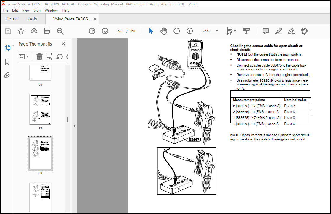
Fault tracing of cables and connectors …………… 24
Checking the starter motor voltage………………… 26
Checking the charging system ……………………… 27
Rail pressure measurement………………………….. 28
Malfunctions ……………………………………………….. 29
Fault code information …………………………………. 29
FMI table / SAE standard ……………………………. 30
Manual fault tracing in bus cables …………………. 33
Diagnostic Trouble Codes ……………………………. 34
MID 128, PID 45
Inlet air heater status ………………………………….. 34
MID 128, PID 94
Fuel pressure …………………………………………….. 37
MID 128, PID 97
Water in fuel ………………………………………………. 43
MID 128, PID 100
Oil pressure ………………………………………………. 46
MID 128, PID 105
Boost temperature ……………………………………… 52
MID 128, PID 106
Boost pressure…………………………………………… 58
7747632 English 03–2007
© 2007 AB VOLVO PENTA
We reserve the right to make modifications without prior notice.
Printed on environmentally compatible paper.
MID 128, PID 108
Ambient air pressure …………………………………… 64
MID 128, PID 110
Coolant temperature ……………………………………. 66
MID 128, PID 111
Coolant level ……………………………………………… 72
MID 128, PID 158
Battery voltage…………………………………………… 76
MID 128, PID 164
Rail pressure ……………………………………………… 78
MID 128, PID 190
Engine speed …………………………………………….. 84
MID 128 / MID 144, PPID 4
Start input CIU …………………………………………… 85
MID 128 / MID 144, PPID 6
Engine stop switch ……………………………………… 87
MID 128, PPID 19
Internal EGR status ……………………………………. 89
MID 128, PPID 55
EMS temperature ……………………………………….. 93
MID 128, PPID 98
Engine sync acknowledge ……………………………. 95
MID 128 / 144, PPID 132
Throttle input request failure, DCU/CIU ………….. 97
MID 128, SID 1-6
Injector common rail # 1-6 ……………………………100
MID 128, SID 21
Speed sensor camshaft ………………………………105
MID 128, SID 22
Speed sensor, crankshaft ……………………………110
MID 128, SID 39
Engine starter relay …………………………………….115
MID 128, SID 42
Injection control pressure regulator ………………..118
MID 128, SID 70
Preheat sense ……………………………………………122
MID 128, SID 211
5V sensor supply 2 …………………………………….124
MID 128, SID 231
Communication fault J 1939 …………………………126
MID 128, SID 232
5V sensor supply 1 …………………………………….129
MID 128, SID 240
Program memory ……………………………………….131
MID 128, SID 254
Controller error …………………………………………..132
MID 128, PSID 96
Rail pressure system ………………………………….133
MID 128, PSID 97
Rail pressure release valve ………………………….137
MID 128 / MID 144, PSID 201
J1939 communication bus …………………………..141
Engine protection ……………………………………….144
TAD 650, 660, 750, 760 VE …………………………144
TAD 734 GE ……………………………………………..145
Wiring diagrams………………………………………….146
Wiring diagram EMS 2:
Vechicle harness TAD 650-760VE ……………….146
Engine harness TAD 650-760VE ………………….147
Engine harness TAD 734GE ……………………….148
Wiring diagram DCU ……………………………………149
Wiring diagram CIU …………………………………….150
Technical data …………………………………………….151
Switch, water in fuel ……………………………………151
Sensor, fuel pressure ………………………………….151
Speed sensor, camshaft /
Speed sensor, crankshaft ……………………………151
Sensor, oil pressure ……………………………………151
Sensor, rail pressure …………………………………..151
Combination sensor,
boost pressure/boost temperature …………………152
Sensor, coolant temperature ………………………..152
Switch, coolant level …………………………………..152
Alternator ………………………………………………….152
Starter motor ……………………………………………..152
Index ………………………………………………………….153
References to Service Bulletins ……………………153
More products