$39
Wacker Neuson Dumpers 6001 Service Manual_366855486 – PDF DOWNLOAD
Wacker Neuson Dumpers 6001 Service Manual_366855486 – PDF DOWNLOAD
FIILE DETAILS:
Wacker Neuson Dumpers 6001 Service Manual_366855486 – PDF DOWNLOAD
Language : English
Pages :300
Downloadable : Yes
File Type : PDF
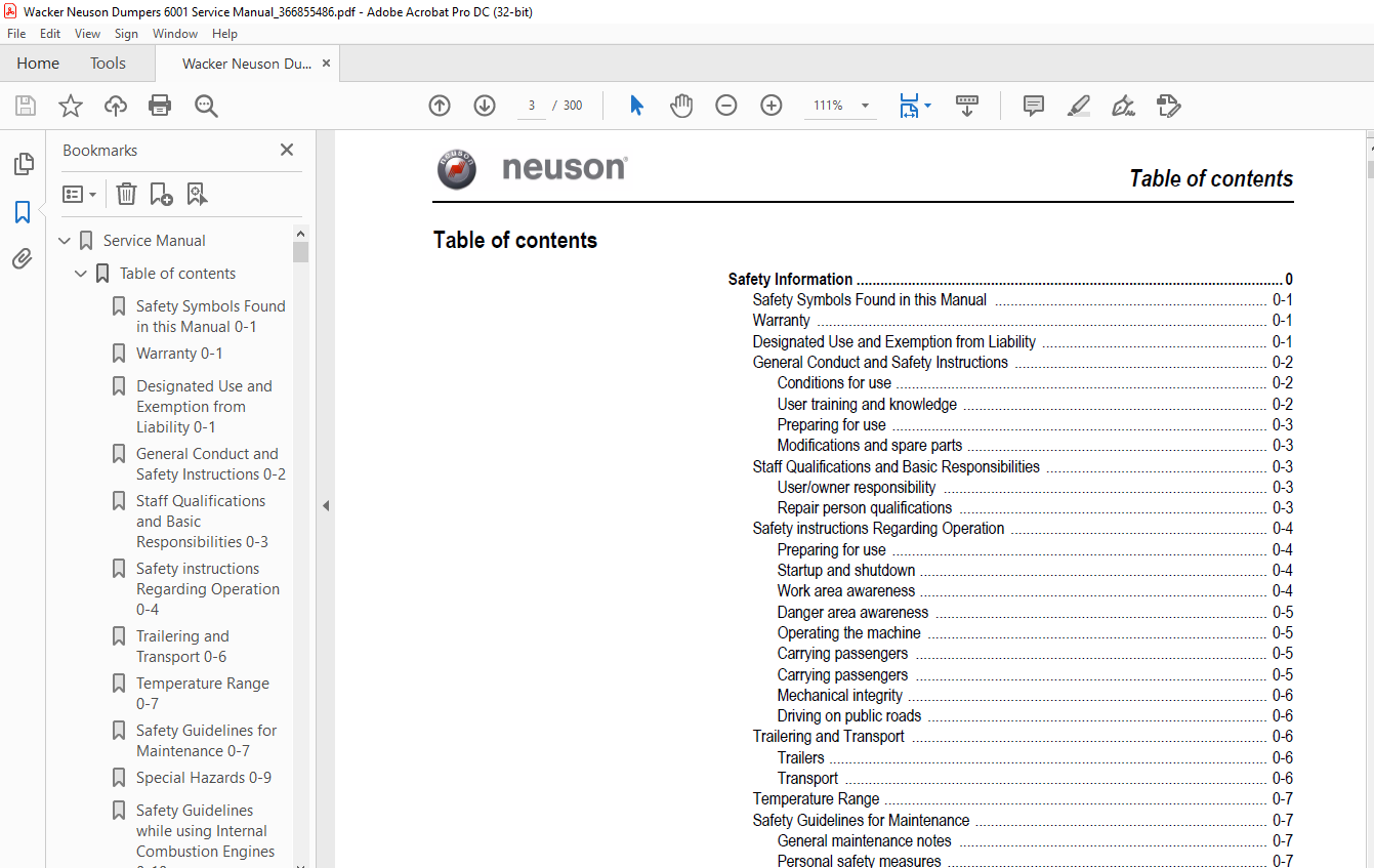
TABLE OF CONTENTS:
Wacker Neuson Dumpers 6001 Service Manual_366855486 – PDF DOWNLOAD
Safety Information 0
Safety Symbols Found in this Manual 0-1
Warranty 0-1
Designated Use and Exemption from Liability 0-1
General Conduct and Safety Instructions 0-2
Conditions for use 0-2
User training and knowledge 0-2
Preparing for use 0-3
Modifications and spare parts 0-3
Staff Qualifications and Basic Responsibilities 0-3
User/owner responsibility 0-3
Repair person qualifications 0-3
Safety instructions Regarding Operation 0-4
Preparing for use 0-4
Startup and shutdown 0-4
Work area awareness 0-4
Danger area awareness 0-5
Operating the machine 0-5
Carrying passengers 0-5
Carrying passengers 0-5
Mechanical integrity 0-6
Driving on public roads 0-6
Trailering and Transport 0-6
Trailers 0-6
Transport 0-6
Temperature Range 0-7
Safety Guidelines for Maintenance 0-7
General maintenance notes 0-7
Personal safety measures 0-7
Preparing for maintenance and repair work 0-8
Performing maintenance and repairs 0-8
Special Hazards 0-9
Battery 0-9
Tracks (Track dumpers) 0-9
Electric energy 0-9
Hydraulics 0-9
Noise 0-10
MSDS 0-10
Tires (Wheel dumpers) 0-10
Safety Guidelines while using Internal Combustion Engines 0-10
Guidelines for running the engine 0-10
Guidelines for fueling the engine 0-11
Operation 1
Important information on this Service Manual 1-1
Type labels and component numbers 1-2
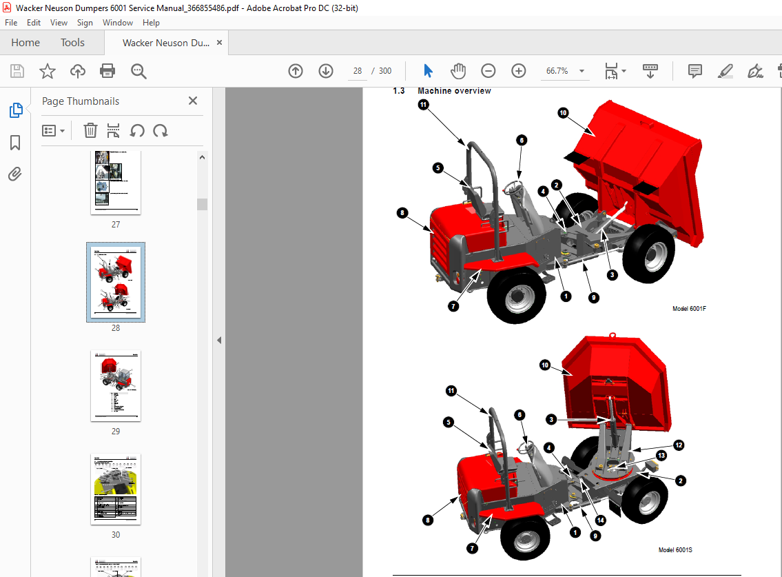
Machine overview 1-5
Operating equipment overview 1-7
Operating equipment (legend) 1-7
Operating equipment (legend) 1-8
Control stand 1-9
Instrument panel 1-12
Dumper without cab (up to AB60997D) 1-12
Dumper with cab (option) up serial number AB60997D 1-13
Dumper without/with cab (option) from serial number AD60001D 1-14
Table of contents
T-2 SERV-HB 6001 EN – Edition 20 * Sh6001En_0IVZfm
Table of contents
Maintenance prop 1-15
Front skip maintenance prop 1-15
Swivel skip maintenance prop 1-16
Centre pivot prop 1-16
Specifications2
Chassis 2-1
Engine 2-1
Engine capacities 2-2
Engine tightening torques 2-2
Travelling drive 2-2
Brakes 2-2
Steering system 2-3
Work hydraulics 2-3
Loader unit 2-3
Drive specifications 2-3
Vibration 2-3
Electric system 2-4
Up to serial no AB60997D 2-4
From serial no AD60001D 2-5
Tyres 2-6
Noise levels 2-6
Coolant compound table 2-7
General tightening torques 2-7
Tightening torques for hydraulic screw connections (dry assembly) 2-7
Tightening torques for high-resistance screw connections 2-9
Tightening torques for Nordlock lock washers 2-10
Dimensions model 6001 (up to AB60997D) 2-11
Dimensions model 6001 HF (Hydrostat/front tip) 2-12
Dimensions model 6001 HF (Hydrostat/front tip) with cab 2-13
Dimensions model 6001 HS (Hydrostat/swivel) 2-14
Dimensions model 6001 HS (Hydrostat/swivel) with cab 2-15
Maintenance 3
Engine/machine fluids and lubricants (up to AB60997D) 3-1
Maintenance plan (overview) 3-3
Service package 3-6
Up to serial no AB60997D 3-6
From serial no AD60001D 3-6
Introduction 3-6
Fuel system 3-7
Specific safety instructions 3-7
Refuelling 3-7
Stationary fuel pumps 3-8
Diesel fuel specification 3-8
Bleeding the fuel system 3-8
Fuel prefilter with water separator (up to serial no AB60997D) 3-9
Replacing the fuel filter 3-10
Engine lubrication system 3-11
Checking the oil level 3-11
Filling up engine oil 3-12
Changing engine oil 3-13
Replacing the engine oil filter cartridge 3-14
Cooling system 3-15
Specific safety instructions 3-15
Checking/filling up coolant 3-16
Draining coolant 3-18
SERV-HB 6001 EN – Edition 20 * Sh6001En_0IVZfm T-3
Table of contents
Air filter 3-19
Weekly check of air filter for dirt 3-19
Replacing the filter 3-20
Functional check once a week of the dust valve 3-21
V-belt 3-21
Checking V-belt tension 3-21
Retightening the V-belt 3-22
Gearbox lubrication system (up to AB60997D) 3-24
Checking the oil level 3-24
Filling up gearbox oil 3-25
Changing gearbox oil 3-26
Replacing the gearbox oil filter cartridge 3-27
Hydraulic system 3-28
Specific safety instructions 3-28
Checking the hydraulic oil level 3-29
Filling up hydraulic oil 3-29
Changing hydraulic oil 3-30
Monitoring the hydraulic oil reflux filter 3-30
Replacing the hydraulic oil reflux filter 3-30
Checking hydraulic pressure lines 3-31
Lubrication points 3-32
Tyre maintenance and checks 3-33
Checks once a day 3-33
Checks once a week 3-33
Changing wheels 3-34
Removing the wheels 3-34
Fitting the wheels 3-34
Axles 3-35
Checking the oil level and filling up oil 3-35
Draining oil 3-35
Electric system 3-36
Specific safety instructions 3-36
Service and maintenance work at regular intervals 3-36
Instructions concerning specific components 3-37
Alternator 3-37
Battery 3-38
General maintenance work 3-40
Cleaning 3-40
General instructions for all areas of the machine 3-40
Exterior of the machine 3-41
Engine compartment 3-41
Screw connections and attachments 3-41
Pivots and hinges 3-41
Engine 4
Engine overview 1104 C-44 4-1
Engine overview 1104 C-44T 4-3
Fuel system 4-5
Checking and adjusting valve clearance 4-6
Tightening order for cylinder head bolts 4-7
Checking the injection nozzles 4-8
Pressure check 4-8
Checking the nozzle jet 4-9
Injection time 4-9
Adjusting engine revs 4-10
Compression 4-10
Checking the coolant thermostat 4-11
T-4 SERV-HB 6001 EN – Edition 20 * Sh6001En_0IVZfm
Table of contents
Checking the thermal switch 4-11
Oil pressure switch 4-12
Checking the coolant circuit 4-12
TD 2011 L04 W engine overview (from serial no AD60001D) 4-13
Fuel system 4-16
Checking and adjusting valve clearance 4-17
Checking and adjusting the fuel injectors 4-18
Adjusting engine revs 4-20
Compression pressure 4-21
Removing/mounting the cylinder head 4-22
Intake/exhaust manifold 4-25
Replacing the injection pump/setting fuel injection time 4-25
Oil pressure switch 4-29
Engine trouble 4-30
Travelling drive5
Torque converter gearbox SS620 (from serial no AA60004D to AB60997D) 5-1
Section SS 600 5-5
Torque converter gearbox PS750 (opt) from serial no AB60078D to AB60997D 5-6
Section PS 750 5-10
Oil level check on torque converter gearbox 5-11
Cardan shaft 5-11
Transfer gearbox (from serial no AA60004D to AB60997D) 5-12
Travelling drive diagram (up to serial no AB60997D) 5-14
Test instructions SS620 5-15
Check: converter pressure 5-15
Check: main pressure 5-16
Check: clutch pressure (forwards & reverse) 5-17
Check: oil cooler flow capacity (in neutral position) 5-18
Test instructions PS750 5-19
Checking converter pressure (up to AB60997D) 5-19
Checking main pressure (up to AB60997D) 5-20
Check: oil cooler flow capacity (in neutral position) up to AB60997D 5-21
Hydrostat (from serial no AD60001D) 5-22
Automotive driving 5-22
Closed circuit with inching valve 5-22
Variant 5-22
Variable displacement motor A6VM160HA2U1 5-23
High-pressure-sensitive regulation 5-23
Travelling drive overview 5-24
Hydraulic diagram 5-24
Replacing external components (hydraulic motor) 5-25
Replacing the rotary shaft lip seal 5-26
Replacing seals 5-27
Control unit 5-27
Sealing the cover 5-29
Hydraulic motor settings 5-31
Checking control initiation 5-31
Checking the settings 5-32
Variable displacement pump A4VG71DA1D8 (from serial no AD60001D) 5-33
Variable displacement pump: diagram 5-35
Variable displacement pump: diagram 5-36
Power train overview 5-37
Connecting plate with valves 5-38
Inching valve 5-39
Inching 5-39
Replacing components (hydraulic pump) 5-40
SERV-HB 6001 EN – Edition 20 * Sh6001En_0IVZfm T-5
Table of contents
Replacing the rotary shaft lip seal 5-40
Seals 5-41
Auxiliary (boost) pump 5-44
Replacing the inching valve 5-44
Towing 5-46
Opening the high-pressure circuit 5-46
Axles 6
Axle type label 6-1
Drain, filler and check plug 6-2
Transfer gearbox 6-3
Tightening torques 6-4
Wheel screws 6-4
General tightening torques (Nm) 6-4
Cardan shaft 6-5
Transfer gearbox (up to serial no AB60997D) 6-6
Semiaxles (up to serial no AB60997D) 6-8
Wheel hub 6-12
Brakes (up to serial no AB60997D) 6-16
Differential (up to serial no AB60997D) 6-22
Drive housing (from serial no AD60001D) 6-24
Semiaxles (from serial no AD60001D) 6-26
Rear axle 6-28
Brakes (from serial no AD60001D) 6-30
Differential (from serial no AD60001D) 6-32
Removing the double cardan shaft (rear axle) 6-33
Assembling the joint housing (rear axle) 6-34
Removing the rear axle planetary drive 6-36
Mounting the rear axle planetary drive 6-39
Special tools 6-43
Brakes 7
Brake circuit (up to serial no AB60997D) 7-1
Brake circuit (from serial no AD60001D) 7-2
Service brake 7-2
Steering system 8
Steering circuit 8-1
Up to serial no AB60997D 8-1
From serial no AD60001D 8-2
Steering unit: diagram 8-3
Up to serial no AB60997D 8-3
From serial no AD60001D 8-3
Function 8-4
Steering unit connections 8-4
Up to serial no AB60997D 8-4
From serial no AD60001D 8-5
Exploded view of steering unit (up to serial no AB60997D) 8-6
Priority valve overview 8-6
Priority valve (legend) 8-6
Hydraulic system 9
Gear pump 9-1
Manual spool connections: overview 9-2
Swivel skip spool (up to serial no AB60997D) 9-2
Swivel skip spool (from serial no AD60001D) 9-3
Front skip spool (up to serial no AB60997D) 9-4
Front skip spool (from serial no AD60001D) 9-5
Dumping the skip: hydraulic diagram 9-6
T-6 SERV-HB 6001 EN – Edition 20 * Sh6001En_0IVZfm
Table of contents
Up to serial no AB60997D 9-6
From serial no AD60001D 9-7
Swivelling the skip (option): hydraulics diagram 9-8
Up to serial no AB60997D 9-8
From serial no AD60001D 9-9
Test instructions 9-10
Checking the work hydraulics on a swivel skip machine 9-10
Checking the work hydraulics on a front skip machine 9-11
A4 diagram (up to serial no AB60997D) 9-12
Diagram (up to AB60997D): legend 9-13
A4 diagram (from serial no AD60001D) 9-14
Diagram (from AD60001D): legend 9-15
A3 hydraulics diagram (up to serial no AB60997D) 9-16
A3 hydraulics diagram (from serial no AD60001D) 9-17
Electric system10
Ohm’s Law (current, voltage, resistance); power 10-1
Measuring equipment, measuring methods 10-1
Relays 10-2
Use, mode of function 10-2
Electric units 10-3
Up to serial no AB60997D 10-3
From serial no AD60001D 10-4
Fuse box 10-4
Relays 10-4
Operating equipment overview 10-5
Operating equipment (legend) 10-5
Operating equipment (legend) 10-6
Dumper with cab (option) from serial number AD60001D 10-7
Wiring diagram legend (up to AB60997D) 10-9
Wiring diagram version 1 A4 (up to AB60997D) 10-10
Wiring diagram legend (from AD60001D) 10-11
A4 wiring diagram (from AD60001D) 10-12
Wiring harness legend 1000129021: main wiring harness (up to AB60997D) 10-13
Wiring harness 1000129021: main wiring harness (up to AB60997D) 10-14
Wiring harness legend 1000174363: main wiring harness (from AD60001D) 10-15
Wiring harness 1000182212: main wiring harness (from AD60001D) 10-17
Wiring harness 1000115003 main wiring harness with Powershift option (legend)
10-18
Wiring harness 1000115003 main wiring harness with Powershift option 10-19
Wiring harness legend 1000115817: additional Powershift electrics 10-20
Shift positions 10-20
Wiring harness 1000115817: additional Powershift electrics 10-21
A3 wiring diagram legend (up to AB60997D) 10-25
A3 wiring diagram (up to AB60997D) 10-26
Wiring diagram legend (from AD60001D) 10-27
A4 wiring diagram (from AD60001D) 10-28
Wiring harness legend 1000115817: additional Powershift electrics 10-29
Shift positions 10-29
Wiring harness 1000115817: additional Powershift electrics 10-30
Wiring harness legend 1000115003: main wiring harness (up to AB60997D) 10-31
Wiring harness 1000115003: main wiring harness (up to AB60997D) 10-32
Wiring harness legend 1000182212: main wiring harness (from AD60001D) 10-33
Wiring harness 1000182212: main wiring harness (from AD60001D) 10-35
Wiring harness 1000115003 main wiring harness with Powershift option (legend)
10-36
Wiring harness 1000115003 main wiring harness (Powershift option) 10-37
SERV-HB 6001 EN – Edition 20 * Sh6001En_0IVZfm T-7
Table of contents
Wiring harness 1000115002 engine wiring harness (legend) 10-38
Wiring harness 1000115002 engine wiring harness 10-39
Wiring harness legend 1000075039/1000115017 telltale/indicator base – ignition lock
base 10-40
Wiring harness 1000075039 telltale/indicator base 10-41
Wiring harness 1000115017 ignition lock base 10-42
Wiring harness legend 1000115006: STVO (Austrian road traffic regulations) wiring
harness (up to AB60997D) 10-43
Wiring harness 1000115006: STVO (Austrian road traffic regulations) wiring harness
(up to AB60997D) 10-44
Wiring harness legend 1000174957: STVO (Austrian road traffic regulations) wiring
harness (from AD60001D) 10-45
Wiring harness: STVO (Austrian road traffic regulations) wiring harness 1000174957
(from AD60001D) 10-46
IMAGES PREVIEW OF THE MANUAL:
More products