$45
Wacker Neuson Group Telehandlers TH522 Service Manual PDF DOWNLOAD
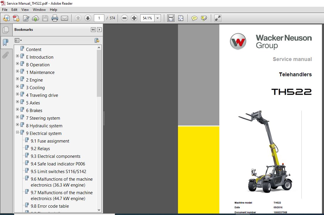
Wacker Neuson Group Telehandlers TH522 Service Manual
FILE DETAILS:
Wacker Neuson Group Telehandlers TH522 Service Manual
Language : English
Pages : 574
Downloadable : YES
Format : PDF
Size : 81.8 MB
DESCRIPTION:
Wacker Neuson Group Telehandlers TH522 Service Manual
INTRODUCTION:
This Service Manual is designed to help maintain the constant serviceability of your vehicle. Subsequently, this assures the high value of the vehicle thanks to careful care and customer-service monitoring. The experience of our customer service technicians and practical experience are concentrated in this Service Manual. The sequence of images illustrates the repair procedure.
- The text provides the necessary information for making adjustments, using special tools, etc. The main types of maintenance work are listed in such a way that individual tasks and more minor tasks are comprehendible and easily found.
- The book is supplemented to reflect the technical further development of the vehicle and is therefore always up to date as a means of reference. To be on the safe side, please always compare the adjustment values and capacities with the current operating manual of the respective machine. Technical data, dimensions and weights are only given as an indication. Responsibility for errors or omissions not accepted. Some pictures can differ visually from the actual object.
TABLE OF CONTENTS:
Wacker Neuson Group Telehandlers TH522 Service Manual
E Introduction
E1 About this Service Manual E-1
E2 Tightening torques E-7
E3 Safety instructions E-19
B Operation
B1 Overview of control elements B-2
B2 Indicator lights and warning lights (overview) B-14
B3 Steering system B-31
B4 Accelerator actuation B-33
B5 Brakes B-35
B6 Travel operation B-36
B7 Differential lock (option) B-43
B8 Lights/signaling system B-45
B9 Wiper/washer system B-49
B10 Heating, ventilation and air conditioning system B-50
B11 Operating hydraulics B-52
B12 Attachments B-65
B13 Work operation B-71
B14 Emergency lowering B-84
B15 Options B-86
1 Maintenance
11 Information on maintenance 1-1
12 Maintenance overview 1-7
13 Fluids and lubricants 1-17
14 Maintenance accesses 1-19
15 Cleaning and maintenance 1-20
16 Lubrication work 1-22
17 Fuel system 1-22
18 Engine lubrication system 1-29
19 Cooling system 1-31
110 Air filter 1-35
111 V-belt/toothed belt 1-37
112 Hydraulic system 1-39
113 Electrical system 1-43
114 Heating, ventilation and air conditioning system (option) 1-48
115 Washer system 1-51
116 Axles/traveling drive 1-52
117 Braking system 1-53
118 Tires 1-54
119 Maintenance and servicing work on attachments 1-57
120 Maintenance of options 1-58
121 Exhaust gas treatment 1-59
2 Engine
21 Complete component (engine 367 kW) 2-1
22 Alternator (367 kW) 2-27
23 Motor starter M001 (367 kW) 2-31
24 Complete component (engine 443 kW) 2-33
25 Alternator (443 kW) 2-59
26 Motor starter M001 (443 kW) 2-63
27 Diesel particulate filter (engine 443 kW) 2-65
28 Fuel tank 2-67
29 Tank sensor B001 2-77
Content
I-2 SHB TH522 30 * SHB_TH522_V3_enIVZfm
I
3 Cooling
31 Coolant reservoir 3-2
4 Traveling drive
41 Cardan shaft 4-2
42 Servomotor M17/M18 4-5
43 Type label – transfer gearbox 4-11
44 Tightening torques and screw locking 4-13
45 Drain, filler and check plugs 4-15
5 Axles
51 Front axle 5-1
52 Rear axle 5-11
53 Type plate – front/rear axle 5-27
54 Tightening torques and screw locking 5-29
55 Drain, filler and check plugs 5-35
6 Brakes
61 Replacing brake linings 6-2
7 Steering system
71 Steering orbitrol S8 7-1
72 Steering mode valve V64 7-3
8 Hydraulic system
81 Hydraulic oil tank Z41 8-1
82 Variable displacement pump P34/P35 8-3
83 Quickhitch 8-7
84 Telescopic boom 8-15
85 Lift cylinder A57 8-25
86 Push-out cylinder A59 8-31
87 Tilt cylinder A58 8-39
88 Compensation cylinder A60 8-47
89 Designation of hydraulic components 8-53
810 Hydraulics diagram – variant 1 8-55
811 Hydraulics diagram – variant 2 8-57
812 Hydraulic diagram – variant 3 8-59
813 Hydraulics diagram – variant 4 8-61
814 Hydraulics diagram – variant 5 8-63
815 Hydraulics diagram – 4-way control valve 8-65
816 Hydraulics diagram – 5-way control valve 8-67
817 Hydraulics diagram – 6-way control valve 8-69
818 Hydraulics diagram – 7-way control valve 8-71
819 Hydraulics diagram – 8-way control valve 8-73
820 Hydraulics diagram – compensating and lift cylinder 8-75
821 Hydraulics diagram – push-out cylinder 8-77
822 Hydraulics diagram – tilt cylinder 8-79
823 Hydraulics diagram – steering system 8-81
824 Hydraulic circuit diagram – brakes 8-83
825 Hydraulic circuit diagram – differential lock 8-85
826 Hydraulics diagram – 3rd control circuit parallel / 4th control circuit parallel with switchover valve 8-87
827 Hydraulics diagram – 3rd control circuit serial / 4th control circuit parallel 8-89
828 Hydraulics diagram – 3rd and 4th control circuit parallel, rear hydraulic connections serial 8-91
829 Hydraulics diagram – 3rd / 4th control circuit and rear hydraulics parallel, rear hydraulic
connections serial 8-93
830 Hydraulics diagram – 3rd / 4th control circuit and rear hydraulics parallel, rear hydraulic
connections serial, HighFlow and PTO shaft single-acting 8-95
SHB TH522 30 * SHB_TH522_V3_enIVZfm I-3
I
9 Electrical system
91 Fuse assignment 9-2
92 Relays 9-4
93 Electrical components 9-4
94 Safe load indicator P006 9-5
95 Limit switches S116/S142 9-9
96 Malfunctions of the machine electronics (363 kW engine) 9-13
97 Malfunctions of the machine electronics (447 kW engine) 9-15
98 Error code table 9-17
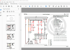
99 Electrical diagram – electronics, power supply 9-19
910 Electrical diagram – Perkins 404D-22 engine 9-20
911 Electrical diagram – Perkins 404D-22 engine 9-21
912 Electrical diagram – Perkins 404F-22 engine 9-22
913 Electrical diagram – Perkins 404F-22 engine 9-23
914 Electrical diagram – Ciam instrument 9-24
915 Electrical diagram – Bauser instrument 9-25
916 Electrical diagram – drive function 9-26
917 Electrical diagram – extension and retraction; VLS; Load control 9-27
918 Electrical diagram – indicator system; Horn 9-28
919 Electrical diagram – StVZO (German traffic regulations) lights 9-29
920 Electrical diagram – StVZO (German traffic regulations) lights 9-30
921 Electrical diagram – working lights; Rotating beacon 9-31
922 Electrical diagram – air conditioning; Seat 9-32
923 Electrical diagram – wiper 9-33
924 Electrical diagram – 12V electrical connection; Hydraulic control circuits 9-34
925 Electrical diagram – Hydraulics 1 9-35
926 Electrical diagram – Hydraulics 2 9-36
927 Electrical diagram – Radio; Cigarette lighter socket; Interior light 9-37
928 Electrical diagram – rear force sensorr 9-38
929 Electrical diagram – steering mode switchover 9-39
930 Designation of electrical components 9-41
931 Connector pin assignment 9-51
932 Pin assignment (only 337 kW engine) 9-71
933 Pin assignment (only 443 kW engine) 9-74
10 Trim
101 Engine cover 10-1
102 Underride protection 10-5
103 Rear covers 10-7
104 Cabin covers 10-9
11 Cabin
111 Seat 11-1
112 Cabin 11-5
113 Air conditioning cooler 11-15
114 Air conditioning system compressor Y031 11-17
12 Automatic coupling
121 Ball coupling 12-12
122 Automatic/rotating trailer coupling 12-16
123 Self-securing coupling 12-18
13 Switch
131 Overview of switch assignment 13-2
Index
INDEX:
A
Abbreviations E-3
Accident prevention regulations
general information E-20
Adding hydraulic oil 1-41
Adjusting the pallet forks B-82
Air conditioning
Disassemble 11-17
Disassemble compressor 11-17
Removing the condenser 1-34
Air conditioning compressor
Disassemble 11-17
Air conditioning cooler
Disassemble 11-15
Install 11-15
Alternator
Disassemble 2-27, 2-59
Install 2-29, 2-61
Attachments
Bucket B-74
Coupling B-68
Fork-and-grab attachment B-80
Maintenance 1-57
Manure forks B-79
Pallet forks B-81, B-83
Universal bucket B-77
Automatic trailer coupling
Disassemble 12-16
Install 12-16
B
Ball coupling
Disassemble 12-13
Install 12-13
Battery
Emergency starting/jump-starting 1-46
Battery master switch B-42, 1-5
Bleed the fuel system 1-28
Brake/inching pedal B-35
Brakes
Replacing brake linings 6-2
C
Cabin
Disassemble 11-5
Install 11-10
Cabin covers
Disassemble 10-9
Install 10-10
Cardan shaft
Disassemble 4-2
Central lubrication system B-93
Checking the antifreeze mixture 1-33
Checking the brake-fluid level 1-53
Checking the hydraulic oil level 1-41
Checking/cleaning/replacing the engine air filter 1-36
Cleaning and maintenance 1-20
Compensating ram
Disassemble 8-47
Compensation cylinder
Install 8-50
Compressor air conditioning system
Disassemble 11-17
Install 11-17
Connector
Pin assignment 9-51
Control elements
Overview B-3
Coolant reservoir
Disassemble 3-2
Install 3-3
Cooling system
Checking the antifreeze mixture 1-33
Checking/adding coolant 1-31
Clean 1-33
D
Designation
Electrical components 8-53, 9-41
Hydraulic components 8-53
Differential housing
Screw lock 5-32
Tightening torques 5-31, 5-32
Differential lock B-44
Index
S-2 SHB TH522 30 * SHB_TH522_V2_enSIXfm
S
E
Electrical components 9-4
Electrical diagram
12 V power outlet 9-37
12V electrical connection 9-34
Air conditioning 9-32
Bauser instrument 9-25
Ciam instrument 9-24
Drive function 9-26
Electronics 9-19
Extension and retraction 9-27
Horn 9-28
Hydraulic control circuits 9-34
Hydraulics1 9-35
Hydraulics2 9-36
Interior light 9-37
Load control 9-27
Perkins 404D-22 engine 9-20, 9-21
Perkins 404F 22-T engine 9-22, 9-23
Power supply 9-19
Radio 9-37
Rear force sensor 9-38
Rotating beacon 9-31
Seat 9-32
Steering mode switchover 9-39
StVZO (German traffic regulations) lights 9-29,
9-30
Turn indicator system 9-28
VLS 9-27
Wiper 9-33
Working lights 9-31
Electrical system
Fuses and relays 1-43
Units 9-4
Emergency lowering B-84
Emergency starting/jump-starting 1-46
Engine
Checking the engine-oil level 1-29
Disassemble 2-6, 2-37
Install 2-16, 2-48
Preheating B-95
Engine cover
Disassemble 10-2
Install 10-3
Engine lubrication system 1-29
Engine oil and hydraulic oil preheating B-95
Error code table 9-17
Excavation work B-76
Exchanging attachments B-65
Explanation of symbols E-3
F
Filling the central lubrication system 1-58
Filling up the washer system 1-51
Fluids and lubricants 1-17
Front axle
Check plug 5-35
Disassemble 5-3
Drain plug 5-35
Filler plug 5-35
Install 5-7
Threaded fittings 4-13, 5-29
Type label 4-11, 5-27
Front cardan shaft
Install 4-3
Front wiper/washer system B-49
Fuel sensor
Disassemble 2-77
Install 2-78
Fuel tank
Disassemble 2-68
Install 2-72
Fuse assignment 9-2
G
General regulations
Accident prevention E-20
Safety E-20
General safety check 1-21
H
handling
Repair book E-2
Hydraulic oil reservoir
Disassemble 8-2
Install 8-2
Hydraulic system
Breather filter 1-40
Hydraulic oil 1-40
Hydraulics diagram
3rd control circuit parallel 8-87, 8-91, 8-93, 8-95
3rd control circuit, serial 8-89
4th control circuit parallel with switchover valve
SHB TH522 30 * SHB_TH522_V2_enSIXfm S-3
S
8-87
4th control circuit, parallel 8-89, 8-91, 8-93, 8-95
4-way control valve 8-65
5-way control valve 8-67
6-way control valve 8-69
7-way control valve 8-71
8-way control valve 8-73
Brakes 8-83
Compensating ram 8-75
Differential lock 8-85
HighFlow and PTO shaft single-acting 8-95
Lift cylinder 8-75
Push-out cylinder 8-77
Rear connections serial 8-91, 8-93, 8-95
Rear hydraulics, parallel 8-93, 8-95
Steering system 8-81
Tilt cylinder 8-79
Variant 1 8-55
Variant 2 8-57
Variant 3 8-59
Variant 4 8-61
Variant 5 8-63
I
Inflating the tires 1-55
L
Lift cylinder
Disassemble 8-25
Install 8-27
Limit switch
Adjust 9-9
Load sensor
Install 9-10
Loader unit control lever B-52
Loader unit stabilizer B-92
Locking the loader unit B-57
M
Machine
Cleaning 1-21
Lubrication 1-22
Maintenance
Air conditioning 1-49
Attachments 1-57
Axles 1-52
Bleed the fuel system 1-28
Braking system 1-53
Cabin breather filter 1-48
Checking the brake-fluid level 1-53
Cleaning the condenser of the air conditioning system
1-49
Engine air filter 1-36
Fuel/water separator 1-25, 1-27
Inflating the tires 1-55
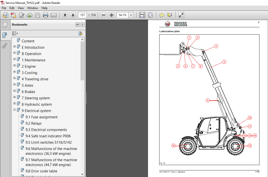
Lubrication plan 1-15
Tires 1-54
Washer system 1-51
Maintenance access
Transmission tunnel cover 10-5, 10-7
Malfunctions
of the machine electronics (363 kW engine) 9-13
of the machine electronics (447 kW engine) 9-15
Manual inching B-91
O
Operation
Central lubrication system B-94
Differential lock B-44
Electric power outlet on the loader unit B-86
Emergency lowering B-84
Engine speed setting B-91
Fan B-50
Horn B-48
Locking the loader unit B-57
Low/high beam B-46
Manual speed control adjustment B-91
Travel mode B-38
Working lights B-45
Operator seat
Disassemble 11-2
Install 11-3
Overview
Switch assignment 13-2
P
Parking brake B-35
Planetary drive housing
Tightening torques 5-33
Plug
Tightening torques 5-31
Push-out cylinder
Disassemble 8-31
Install 8-34
Q
Quickhitch
Disassemble 8-8, 8-11
Install 8-11
S-4 SHB TH522 30 * SHB_TH522_V2_enSIXfm
S
R
Rear axle
Check plug 5-36
Disassemble 5-12
Drain plug 5-36
Filler plug 5-36
Install 5-18
Threaded fittings 4-13, 5-29
Type label 4-11, 5-27
Rear cover
disassemble 10-7
Rear hydraulic connection B-26
Rear hydraulic connections B-96
Rear wiper B-49
Reduction gear
Screw lock 5-29
Tightening torques 5-29
Refueling with diesel fuel 1-23
Relays 9-4
Repair book
handling E-2
Repair Instructions
Cause of Damage E-4
Diesel engine E-4
Gearbox E-4
Spare Parts E-4
Technical Specifications E-4
Replacing brake linings
Parking brake 6-2
Service brake 6-4
Residual pressure in hydraulic system B-85
Reverse warning system B-48
Rotating beacon B-47
S
Safe load indicator
0%-point calibration 9-6
100%-point calibration 9-6
calibrate 9-5
Safety E-19
Safety regulations
general information E-20
Screw connections E-5
Screw dimensions E-7
Self-securing coupling
Disassemble 12-18
Install 12-18
Signal words E-19
Starter
Disassemble 2-31, 2-63
Install 2-32, 2-64
Steering cylinder
Tightening torques 5-30
Steering modes B-31
Switch assignment
Overview 13-2
T
Technical data
Electrical components 9-4
Telematik B-104
Telescopic boom
Disassemble 8-16
Install 8-20
Tightening torques
adjustable hydraulic screw struts E-16
brake line screw connections E-18
climate screw fixtures E-10
general information E-7
hollow screws E-15
hydraulic screw connections E-10, E-11
hydraulic screw struts E-12
hydraulic swivel screw fittings E-15
metric fine threads E-9
metric regulation threads E-8
specific E-7
worm drive clips E-18
Tilt cylinder
Disassemble 8-40
Install 8-43
Tools E-5
Transfer case 20 km/h
Check plug 4-15
Drain plug 4-15
Filler plug 4-15
Tightening torques 4-13
Transfer case 30 km/h
Check plug 4-16
Drain plug 4-16
Filler plug 4-16
Screw lock 4-14
Tightening torques 4-14
Transfer gearbox
Type label 4-11
Transmission tunnel cover
Install 10-7
Travel direction selection B-37
Travel mode B-38
Turn indicators B-46
U
Underride protection
Disassemble 10-5
Install 10-6
V
Variable displacement motor
Disassemble 4-8
Install 4-9
VIDEO PREVIEW OF THE MANUAL:
IMAGES PREVIEW OF THE MANUAL:
More products