$34
Wacker Neuson Lifton Dumper 1501 Service Manual_1000144667 – PDF DOWNLOAD
Wacker Neuson Lifton Dumper 1501 Service Manual_1000144667 – PDF DOWNLOAD
FILE DETAILS:
Wacker Neuson Lifton Dumper 1501 Service Manual_1000144667 – PDF DOWNLOAD
Language : English
Pages :142
Downloadable : Yes
File Type : PDF
TABLE OF CONTENTS:
Wacker Neuson Lifton Dumper 1501 Service Manual_1000144667 – PDF DOWNLOAD
Operation
Important information on this service manual 1-1
Identification of warnings and dangers 1-2
Designated use and exemption from liability 1-3
Type labels and component numbers 1-4
Machine overview 1501 1-6
Machine overview 1501S 1-7
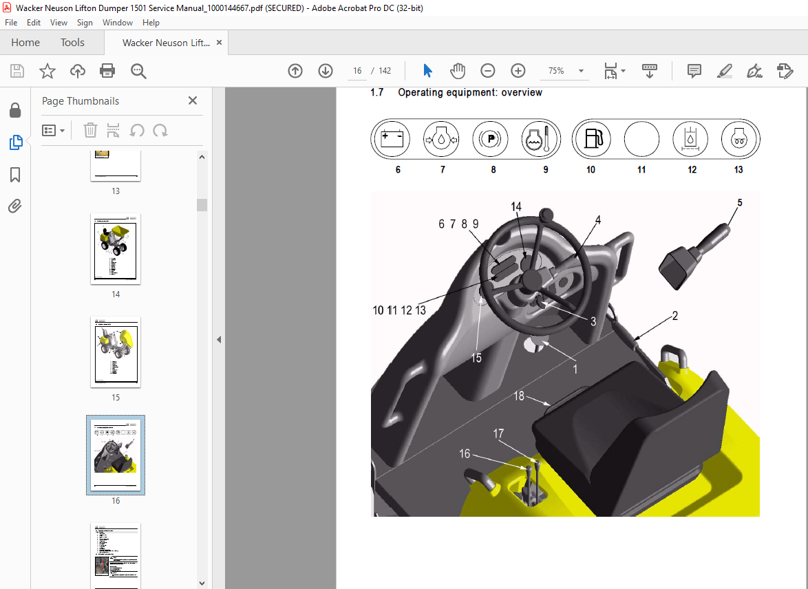
Operating equipment: overview 1-8
Operating equipment: legend 1-9
Maintenance prop, model 1501 1-9
Maintenance prop, model 1501S 1-10
Articulated joint prop, model 1501/1501S 1-11
Specifications
Chassis 2-1
Engine 2-1
Engine capacities 2-1
Engine tightening torques 2-2
Travelling drive 2-2
Brakes 2-2
Steering system 2-2
Work hydraulics 2-2
Loader unit 2-3
Drive specifications 2-3
Electric system 2-4
Fuse box 2-4
Relays 2-4
Tyres 2-5
Noise levels 2-5
Coolant compound table 2-5
General tightening torques 2-6
Tightening torques for hydraulic screw connections (dry assembly) 2-6
Tightening torques for high-resistance screw connections 2-8
Tightening moments for Nordlock lock washers 2-9
Dimensions model 1501 2-10
Dimensions model 1501S 2-11
Maintenance
Fluids and lubricants 3-1
Maintenance plan (overview) 3-3
Service package 3-7
Introduction 3-7
Fuel system 3-8
Specific safety instructions 3-8
Refuelling 3-8
Stationary fuel pumps 3-8
Diesel fuel specification 3-9
Bleeding the fuel system 3-9
Fuel prefilter with water separator 3-10
Replacing the fuel filter 3-11
Engine lubrication system 3-12
Checking the oil level 3-12
Filling up engine oil 3-13
Changing engine oil 3-13
Replacing the engine oil filter cartridge 3-15
I-2 SERV-HB 1501En – Ausgabe 10 * * 1501s11IVZfm
Cooling system 3-16
Specific safety instructions 3-16
Checking/filling up coolant 3-17
Draining coolant 3-18
Air filter 3-19
Check once a week of air filter contamination 3-19
Replacing the filter 3-20
V-belt 3-21
Checking V-belt tension 3-21
Retightening the V-belt 3-22
Hydraulic system 3-23
Specific safety instructions 3-23
Checking the hydraulic oil level 3-23
Filling up hydraulic oil 3-24
Changing hydraulic oil 3-25
Monitoring the hydraulic oil reflux filter 3-25
Replacing the hydraulic oil reflux filter 3-25
Checking hydraulic pressure lines 3-26
Lubrication points 1501: overview 3-27
Lubrication points 1501S: overview 3-28
Tyre maintenance 3-28
Checks once a day 3-29
Checks once a week 3-29
Changing wheels 3-30
Disassembly 3-30
Fitting the wheels 3-30
Electric system 3-31
Specific safety instructions 3-31
Service and maintenance work at regular intervals 3-31
Instructions concerning specific components 3-32
Alternator 3-32
Battery 3-33
Battery master switch 3-34
General maintenance work 3-35
Cleaning 3-35
General instructions for all areas of the machine 3-35
Screw connections and attachments 3-36
Pivots and hinges 3-36
Engine
3TNE74 engine: overview 4-1
Fuel system 4-3
Checking and adjusting valve tip clearance 4-4
Tightening order for cylinder head bolts 4-5
Checking the injection nozzles 4-6
Pressure check 4-6
Checking the nozzle jet 4-6
Injection time 4-7
Adjusting engine revs 4-8
Compression 4-8
Checking the coolant thermostat 4-9
Checking the thermal switch 4-9
Oil pressure switch 4-10
Checking the coolant circuit 4-10
Engine trouble 4-11
Travelling drive
SERV-HB 1501En – Ausgabe 10 * 1501s11IVZfm I-3
Variable displacement pump A10VG45DA 5-1
Variable displacement pump: diagram 5-3
Variable displacement pump: design 5-4
Power train: overview 5-5
Connecting plate with valves 5-6
Rear hydraulic motor 5-7
Front hydraulic motor 5-8
Hydraulic motor: overview 5-9
Drive: overview 5-11
Towing and transporting the machine 5-12
Safety instructions 5-12
Towing 5-12
Open the high-pressure circuit 5-12
Releasing the hydraulic parking brake 5-13
Test instruction 5-14
Pilot pressure check 5-14
High pressure check 5-15
Brakes
Brake circuit up to serial no AC000241 6-1
Brake diagram 6-2
Brake circuit starting serial no AC000242 6-3
Brake diagram 6-4
Steering
Steering circuit 7-1
Steering unit: diagram 7-2
Function 7-2
Steering unit connections 7-3
Steering unit: overview 7-4
Priority valve: overview 7-4
Priority valve: legend 7-4
Steering unit 7-5
Steering unit: legend 7-6
Hydraulic system
Control valve connections: overview 8-1
Test instructions 8-2
Check: work pump pressure 8-2
1501 diagram up to serial no AC000241 8-3
1501 diagram up to serial no AC000241 (legend) 8-4
1501 diagram starting serial no AC000242 8-5
1501 diagram starting serial no AC000242 (legend) 8-6
1501S diagram up to serial no AC000241 8-7
1501S diagram up to serial no AC000241 (legend) 8-8
1501S diagram starting serial no AC000242 8-9
1501S diagram starting serial no AC000242 (legend) 8-10
Hydraulics diagram A3 1501 up to serial no AC000241 8-11
Hydraulics diagram A3 1501 starting serial no AC000242 8-12
Hydraulics diagram A3 1501S up to serial no AC000241 8-13
Hydraulics diagram A3 1501S starting serial no AC000242 8-14
Electric system
Ohm’s Law (current, voltage, resistance); power 9-1
Measuring equipment, measuring methods 9-1
Relays 9-2
Use, mode of function 9-2
I-4 SERV-HB 1501En – Ausgabe 10 * * 1501s11IVZfm
Electric components 9-3
Fuse box in instrument panel 9-3
Relays 9-3
Instrument panel: overview 9-5
Wiring diagram up to serial no AC000241 (legend) 9-8
Wiring diagram version 1 A4 up to serial no AC000242 9-9
Wiring diagram starting serial no AC000242 (legend) 9-10
Wiring diagram version 1 A4 starting serial no AC000242 9-11
Wiring diagram A3 up to serial no AC000241 (legend) 9-14
Wiring diagram A3 up to serial no AC000241 9-15
Wiring diagram A3 starting serial no AC000242 (legend) 9-16
Wiring diagram A3 starting serial no AC000242 9-17
IMAGES PREVIEW OF THE MANUAL:

More products