$34
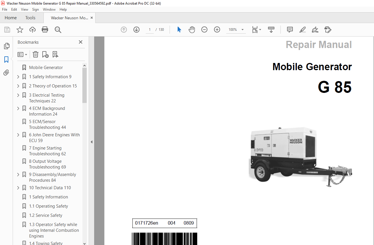
Wacker Neuson Mobile Generator G 85 Repair Manual_330564592 – PDF DOWNLOAD
Wacker Neuson Mobile Generator G 85 Repair Manual_330564592 – PDF DOWNLOAD
FILE DETAILS:
Wacker Neuson Mobile Generator G 85 Repair Manual_330564592 – PDF DOWNLOAD
Language : English
Pages :130
Downloadable : Yes
File Type : PDF
TABLE OF CONTENTS:
Wacker Neuson Mobile Generator G 85 Repair Manual_330564592 – PDF DOWNLOAD
Safety Information 9
11 Operating Safety 10
12 Service Safety 12
13 Operator Safety while using Internal Combustion Engines 13
14 Towing Safety 14
15 Reporting Trailer Safety Defects 14
2 Theory of Operation 15
21 Basic Schematic 15
22 Introduction 16
23 Terminology 18
3 Electrical Testing Techniques 22
31 Checking Continuity 22
32 Checking Resistance 22
33 Checking Voltage 22
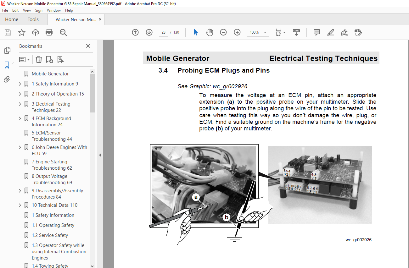
34 Probing ECM Plugs and Pins 23
4 ECM Background Information 24
41 ECM Handling Precaution 24
42 Normal Boot-up Sequence 25
43 Display Variables and Values 28
44 ECM Display Screens—Start Switch in Remote Position 29
45 Additional Variables Monitored by the ECM 30
46 Voltage Display Errors 36
47 ECM Automatic Engine Shutdown Conditions 38
48 ECM Circuit Boards 39
49 Control Wiring Numbering & Colors 40
410 Removing and Installing the ECM 43
Table of Contents MG Repair
wc_br0171726en_004TOCfm 6
5 ECM/Sensor Troubleshooting 44
51 Checking Power to the ECM 44
52 Checking Outgoing Power From the ECM 47
53 Checking Temperature Sender 48
54 Fuel Sender Failure and Low Fuel Fault 50
55 Calibrating ECM Voltage Display 51
56 Calibrating ECM AC Amperage Display 52
57 Calibrating ECM AC Frequency Display 53
58 Calibrating ECM DC Display 54
59 Checking the ECM CAN BUS Circuit 55
510 Checking the Main Circuit Breaker 56
511 ECM Plugs and Pins 57
6 John Deere Engines With ECU 59
61 John Deere Engines With ECU Background 59
62 Locations of Engine Electrical Components 60
63 Engine Electrical Components 61
7 Engine Starting Troubleshooting 62
71 Checking the Fuses 62
72 Checking the Engine Control Module (ECM) 63
73 Checking the Emergency Stop Switch 64
74 Checking the Starter Relay 65
75 Checking the Starter Solenoid 66
76 Checking the Intake Heater Relay 67
77 Checking the Main Circuit Breaker 68
8 Output Voltage Troubleshooting 69
81 Checking the Emergency Stop Switch 69
82 Checking the Lug Door Switch 70
83 Checking the Main Circuit Breaker 71
84 Checking the Voltage Adjusting Rheostat 72
85 Checking the Auxiliary Winding 73
86 Checking the Exciter Stator 74
MG Repair Table of Contents
87 Checking the AVR Sensing Wires 75
88 Flashing the Generator (checking the excitation system) 76
89 Checking Stator Windings at the Lugs 77
810 Checking the Rectifier Diodes—Thread-in Style 78
811 Checking the Rectifier Diodes—Solder-in Style 79
812 Checking the Main Rotor Winding 80
813 Checking the Exciter Rotor Winding 81
814 Checking Stator Windings at the Voltage Selector Switch 82
9 Disassembly/Assembly Procedures 84
91 Tools 84
92 Ordering Parts 84
93 Reference Numbers ( ) 84
94 Weight Block 84
95 Removing the Roof 85
96 Preparing Unit for Generator Removal 87
97 Replacing the Generator 89
98 Removing the AVR 91
99 Installing the AVR 92
910 Removing the Engine 95
911 Installing the Engine 97
912 Replacing the Fuel Tank 99
913 Replacing the Emergency Stop Switch (older) 101
914 Replacing the Emergency Stop Switch (newer) 103
915 Replacing the Diodes 105
916 Replacing the Voltage Selector Switch (VSS) 107
917 G 50, G 70, G 85 VSS Wiring 109
10 Technical Data 110
101 Engine Data 110
102 Generator Data 111
103 Trailer and Skid Data 112
104 Dimensions 113
105 Engine Wiring Diagram—John Deere with ECU 114
106 ECU Wiring Diagram 118
107 ECU Harness Connector 119
108 Generator Wiring Diagram 120
IMAGES PREVIEW OF THE MANUAL:
More products