$34
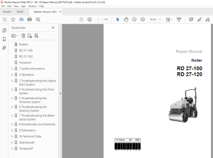
Wacker Neuson Roller RD 27- 100, 120 Repair Manual_360770574
Wacker Neuson Roller RD 27- 100, 120 Repair Manual_360770574 - PDF DOWNLOAD
FILE DETAILS:
Wacker Neuson Roller RD 27- 100, 120 Repair Manual_360770574 - PDF DOWNLOAD
Language : English
Pages :178
Downloadable : Yes
File Type : PDF
TABLE OF CONTENTS:
Wacker Neuson Roller RD 27- 100 120 Repair Manual_360770574 - PDF DOWNLOAD
Rodillo 1
RD 27-100 1
RD 27-120 1
Foreword 3
1 Safety Information 9
11 Signal Words Found in this Manual 9
12 Safety Guidelines for Operating the Machine 10
13 Safety Guidelines while Using Internal Combustion Engines 11
14 Guidelines for Service Safety 12
15 Label Locations 14
16 Safety and Warning Labels 15
17 Informational Labels 18
2 Operation 21
21 Operation & Maintenance Locations 21
22 Using the Forward/Reverse Lever 23
23 Using the Flow Divider (if equipped) 24
24 Using the Vibration System 25
25 Using the Parking Brakes 26
26 Warning Lights 27
27 Using the Lights and Horn 28
28 Preliminary Checks 29
29 Starting the Engine 30
210 Stopping the Engine 31
3 Troubleshooting the Engine Start System 32
31 Determining Where to Begin 32
32 Checking the Fuses 33
Re-install each fuse 33
Replace the faulty fuse with one of like size and rating 33
33 Checking the Wiring/Voltage to the Starter Solenoid 34
If 12V is available at the white wire and the engine doesn’t crank, there is a problem with the starter solenoid or starter motor See the Perkins Engine Repair Manual 34
Check the starting system beginning with the key switch 34
34 Checking the Key Switch 35
Continue 35
Check/repair the brown wire between the key switch fuse and the key switch 35
Continue 35
The key switch has failed; replace it 35
Continue 35
The key switch has failed; replace it 35
The key switch is OK 35
The key switch has failed; replace it 35
35 Checking the Start 2 Relay 36
Continue 36
Check the neutral relay 36
Continue 36
Check condition/continuity of wire 330-YL-16 36
Continued from the previous page 37
Continue 37
The start 2 relay has failed; replace it 37
The start 2 relay is OK 37
The start 2 relay has failed; replace it 37
36 Checking the Neutral Relay 38
Continue 38
Check the neutral switch 38
Continue 38
Repair wire 125-OR-16 38
Continued from the previous page 39
Continue 39
Repair wire 200-BK-16 39
The neutral relay is OK 39
The neutral relay has failed; replace it 39
37 Checking the Neutral Switch 40
The neutral switch is OK 40
The neutral switch has failed; replace it 40
38 Checking the Brake 3 Relay 41
Continue 41
Check the brake switch 41
Continue 41
Repair wire 200-BK-16 41
Continued from the previous page 42
The brake 3 relay is OK 42
The brake 3 relay has failed; replace it 42
39 Checking the Brake Switch 43
Continue 43
The brake switch has failed; replace it 43
The brake switch has failed; replace it 43
Continue 43
Continued from the previous page 44
The brake switch has failed; replace it 44
Continue 44
The brake switch is OK 44
The brake switch has failed; replace it 44
310 Checking Start 1 Relay 45
Continue 45
Repair wire 109-RD-10 45
Continue 45
Repair wire 200-BK-16 45
Continued from the previous page 46
The start 1 relay is OK 46
The start 1 relay has failed; replace it 46
311 Checking the Fuel Flow 47
The fuel flow is OK 47
Check the fuel filter and fuel hoses for clogs or leaks 47
Check the function of the fuel shutoff solenoid 47
312 Checking the Fuel Shutoff Solenoid 48
Continue 48
The fuel shutoff solenoid is OK 48
The fuel shutoff solenoid has failed; replace it 48
313 Checking the Start Aid Relay 49
Continue 49
Check/repair wire 310-PU-16 49
Continue 49
Repair wire 200-BK-16 49
Continue 49
Check/repair wire 109-RD-10 49
Continued from the previous page 50
The start aid relay is OK 50
The start aid relay has failed Replace it 50
4 Troubleshooting the Drive System 51
41 Drive System Overview 51
42 Determining Where to Begin 53
43 Checking the Interlock Relay 54
Continue 54
Repair wire F765-BR-16 54
Continued from the previous page 55
Continue 55
Repair wire 307-OR-16 55
Continue 55
Check the seat switch 55
Continue 55
Repair wire 307-OR-16 55
Continued from the previous page 56
The interlock relay is OK 56
The interlock relay has failed; replace it 56
44 Checking the Seat Switch 57
The seat switch has failed; replace it 57
Continue 57
The seat switch is OK 57
The seat switch has failed; replace it 57
45 Checking the Seat Switch Solenoid Valve 58
Continue 58
The solenoid has failed; replace it 58
The seat switch solenoid valve is OK 58
The seat switch solenoid valve has failed 58
46 Checking the Neutral/Brake Solenoid Valve 59
Continue 59
The solenoid has failed; replace it 59
The neutral/brake solenoid valve is OK 59
The neutral/brake solenoid valve has failed 59
47 Checking the Drive System Operating Pressure 60
48 Testing Drive Motor Integrity 61
Continued from the previous page 62
More than the maximum amount of hydraulic oil is draining Stop the engine and replace the drive motor 62
Less than the maximum amount of hydraulic oil is draining 62
49 Testing the Parking Brakes 63
The brakes are OK 63
The brakes portion of the hydraulic motor is in need of repair 63
410 Checking the Backup Alarm Switch 64
The backup alarm switch is OK 64
The backup alarm switch has failed; replace it 64
5 Troubleshooting the Vibration System 65
51 Determining Where to Begin 66
52 Checking the Vibration Fuse 67
53 Checking the Vibration ON/OFF Solenoid 68
Continued from the previous page 69
Continue 69
The vibration ON/OFF solenoid is OK 69
The vibration ON/OFF solenoid has failed; replace it 69
54 Checking the Neutral Switch 70
Continue 70
The neutral switch has failed; replace it 70
Continued from the previous page 71
The neutral switch has failed; replace it 71
The neutral switch is OK 71
55 Checking the Neutral Relay 72
Continue 72
Check condition/continuity of wire 125-OR-16 72
Continue 72
Check condition/continuity of the wires to the connector 72
The neutral relay is OK 72
The neutral relay has failed; replace it 72
56 Checking the Vibration Switch 73
The vibration switch is OK 73
The vibration switch has failed; replace it 73
57 Checking the Drum Vibration Solenoid 74
Continue 74
Continued from the previous page 75
The drum vibration solenoid is OK 75
The drum vibration solenoid has failed; replace it 75
58 Checking Engine RPM and Drum VPM 76
59 Checking Vibration System Operating and Relief Pressure 77
Continued from the previous page 78
The vibration system operating pressure is OK 78
The vibration system operating pressure is abnormal See chart 78
The vibration system operating pressure is OK 78
The vibration system operating pressure is abnormal See chart 78
Operating 78
Pressure 78
Pump Relief 78
Pressure 78
Exciter Speed 78
Probable Cause 78
Exciter bearings or motor binding 78
Exciter motor worn 78
Exciter pump damaged or worn, relief valve defective, or needs adjusting 78
510 Checking the Vibration Motor for Binding 79
Continued from the previous page 80
Continued from the previous page 81
6 Troubleshooting the Steering System 82
61 Determining Where to Begin 82
62 Diagnosing the Steering System 83
Continue 83
The steering pump has failed; replace it 83
Continued from the previous page 84
The steering cylinder has failed; replace it 84
The steering servo has failed; replace it 84
7 Troubleshooting the Water Spray System 85
71 Determining Where to Begin 85
72 Checking the Water Spray Fuse 86
Re-install the fuse 86
Replace the faulty fuse with one of like size and rating 86
73 Checking Power to the Spray Pump Motor 87
Continue troubleshooting by checking the spray switch 87
74 Checking the Spray Switch 88
Continue 88
Repair wire 118-GY-16 88
Continue 88
The spray switch has failed; replace it 88
The spray switch is OK 88
The spray switch has failed; replace it 88
75 Checking the Timer Module 89
Continue 89
Repair wire 118-GY-16 89
Continued from the previous page 90
Continue 90
Repair wire C935-PU-16 90
Continue 90
Repair wire 200-BK-16 90
Continue 90
Repair wire C937-WH-18 90
The timer module is OK 90
The timer module has failed; replace it 90
76 Checking the Spray Relay 91
Continue 91
Repair wire C720-BU-16 91
Continued from the previous page 92
Continue 92
Repair wire C935-PU-16 92
The spray relay is OK 92
The spray relay has failed; replace it 92
8 Disassembly and Assembly 93
81 Tools Required for Disassembly/Assembly 93
82 Information Regarding Replacement Parts 93
83 Information Regarding Threadlocking Compounds 93
84 Removing and Installing the Steering Servo Valve 94
85 Removing and Installing a Drive Motor 97
86 Removing and Installing an Exciter Motor101
87 Removing a Drum104
88 Disassembling a Drum106
89 Removing and Installing the Exciter Shaft Bearings109
810 Removing and Installing Drum Shock Mounts113
811 Assembling the Drum114
812 Re-installing the Drum116
813 Removing and Installing the Fuel Tank118
814 Removing and Installing the Radiator120
815 Removing and Installing the Steering Cylinder123
816 Removing and Installing the Articulated Steering Joint126
817 Articulated Steering Joint Exploded View128
818 Articulated Steering Joint Components129
819 Rebuilding the Articulated Steering Joint130
821 Removing and Installing the Water Tank135
820 Removing and Installing the Spray System Pump134
822 Removing and Installing the Hydraulic Oil Cooler139
823 Removing and Installing the Drive Pump140
824 Removing and Installing the Steering Pump142
825 Removing and Installing the Vibration Pump145
826 Removing and Installing the Hydraulic Reservoir147
827 Removing and Installing the Engine150
828 Removing and Installing the Forward/Reverse Control (Joystick)158
829 Removing and Installing the Hydraulic Manifold161
9 Schematics162
91 Electrical Schematics162
92 Hydraulic Schematics 0
10 Technical Data169
101 Engine169
102 Roller170
103 Lubrication170
104 Sound Measurements171
105 Measurements of Operator Exposure to Vibration171
106 Dimensions172
Sealantspdf 0
Threadlockers and Sealants173
Torquepdf 0
Torque Values175
Metric Fasteners (DIN)175
Inch Fasteners (SAE)176
IMAGES PREVIEW OF THE MANUAL:
More products