$33
Wacker Neuson Skid Steer Loader 501s Service Manual_1000155663 – PDF DOWNLOAD
Wacker Neuson Skid Steer Loader 501s Service Manual_1000155663 – PDF DOWNLOAD
FILE DETAILS:
Wacker Neuson Skid Steer Loader 501s Service Manual_1000155663 – PDF DOWNLOAD
Language : English
Pages :164
Downloadable : Yes
File Type : PDF
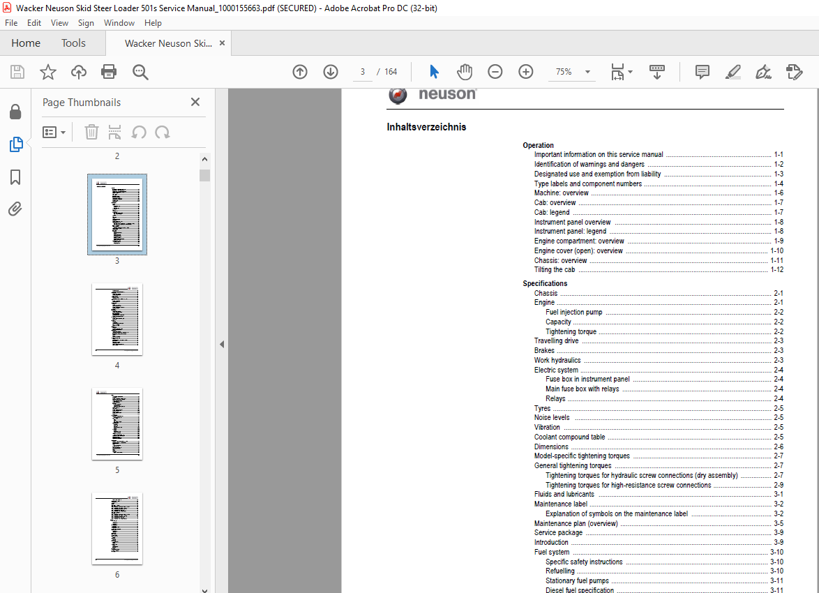
TABLE OF CONTENTS:
Wacker Neuson Skid Steer Loader 501s Service Manual_1000155663 – PDF DOWNLOAD
Operation
Important information on this service manual 1-1
Identification of warnings and dangers 1-2
Designated use and exemption from liability 1-3
Type labels and component numbers 1-4
Machine: overview 1-6
Cab: overview 1-7
Cab: legend 1-7
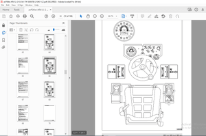
Instrument panel overview 1-8
Instrument panel: legend 1-8
Engine compartment: overview 1-9
Engine cover (open): overview 1-10
Chassis: overview 1-11
Tilting the cab 1-12
Specifications
Chassis 2-1
Engine 2-1
Fuel injection pump 2-2
Capacity 2-2
Tightening torque 2-2
Travelling drive 2-3
Brakes 2-3
Work hydraulics 2-3
Electric system 2-4
Fuse box in instrument panel 2-4
Main fuse box with relays 2-4
Relays 2-4
Tyres 2-5
Noise levels 2-5
Vibration 2-5
Coolant compound table 2-5
Dimensions 2-6
Model-specific tightening torques 2-7
General tightening torques 2-7
Tightening torques for hydraulic screw connections (dry assembly) 2-7
Tightening torques for high-resistance screw connections 2-9
Fluids and lubricants 3-1
Maintenance label 3-2
Explanation of symbols on the maintenance label 3-2
Maintenance plan (overview) 3-5
Service package 3-9
Introduction 3-9
Fuel system 3-10
Specific safety instructions 3-10
Refuelling 3-10
Stationary fuel pumps 3-11
Diesel fuel specification 3-11
Bleeding the fuel system 3-11
Emptying the fuel tank 3-12
Fuel prefilter with water separator 3-12
Replacing the fuel filter 3-13
Engine lubrication system 3-14
Checking the oil level 3-14
Filling up engine oil 3-15
I-2 SERV-HB Skid Steer 501 De – Ausgabe 10 * * 501s11IVZfm
Changing engine oil 3-15
Replacing the engine oil filter cartridge 3-17
Cooling system 3-18
Specific safety instructions 3-18
Checking/filling up coolant 3-19
Draining coolant 3-20
Air filter 3-21
Replacing the filter 3-22
Functional check once a week of the dust valve 3-23
V-belt 3-24
Checking V-belt tension 3-24
Retightening the V-belt 3-25
Pressure check 3-26
General 3-26
Checking boost pressure 3-26
Gear pump pressure check 3-27
Checking the parking brake pressure 3-28
Measuring ports: overview 3-28
Test report 3-29
Hydraulic system 3-31
Specific safety instructions 3-31
Checking the hydraulic oil level 3-32
Filling up hydraulic oil 3-33
Changing hydraulic oil 3-34
Monitoring the hydraulic oil reflux filter 3-34
Checking hydraulic pressure lines 3-35
Travelling drive 3-36
Checking the oil level and filling up oil 3-36
Draining oil 3-36
Tyre care 3-37
Tyre check 3-37
Wheel change 3-37
Raising and jacking up the machine 3-38
Removing the wheels 3-38
Mounting the wheels 3-38
Lubrication work 3-39
Loader unit 3-39
Lubrication points on the bucket 3-39
Maintenance of implements 3-39
Electric system 3-40
Specific safety instructions 3-40
Service and maintenance work at regular intervals 3-40
Instructions concerning specific components 3-41
Alternator 3-41
Battery 3-42
Jump-starting the engine 3-42
General maintenance work 3-43
Cleaning 3-43
General instructions for all areas of the machine 3-43
Inside the cab 3-44
Exterior of the machine 3-44
Engine compartment 3-44
Screw connections and attachments 3-45
Pivots and hinges 3-45
SERV-HB Skid Steer 501 De – Ausgabe 10 * 501s11IVZfm I-3
Engine
3TNV88-XNSS engine: overview 4-1
Fuel system 4-3
Checking and adjusting valve tip clearance 4-4
Tightening order for cylinder head bolts 4-5
Checking the injection nozzles 4-6
Pressure check 4-6
Checking the nozzle jet 4-6
Injection time 4-7
Checking injection time 4-7
Setting injection time 4-7
Replacement of fuel injection pump 4-8
Adjusting engine revs 4-9
Compression 4-9
Checking the coolant thermostat 4-10
Checking the thermal switch 4-10
Oil pressure switch 4-11
Checking the coolant circuit 4-11
Engine trouble 4-12
Hydraulic system
Danfoss MPT 025 hydraulic pump 5-1
Pump unit: exploded view 5-3
Main valve block 5-4
Ports 5-4
Legend 5-4
Main valve block diagram 5-5
Pump sections 5-6
Mechanical control 5-7
Control lever 5-7
Pump control 5-8
Drive control 5-9
Auxiliary hydraulics control 5-10
Function 5-10
Travelling drive 5-11
Function 5-11
Drive (exploded view) 5-12
Travelling drive layout 5-13
Valves 5-14
3/3 directional valve (flush valve) 5-14
Troubleshooting in the hydraulic system 5-15
Hydraulics diagram A4 5-16
Hydraulics diagram (legend) 5-17
Hydraulics diagram 501S A3 5-19
Electric system
Ohm’s Law (current, voltage, resistance); power 6-1
Measuring equipment, measuring methods 6-1
Cable colour coding 6-3
Relays 6-3
Use, mode of function 6-3
Electric components 6-4
Fuse box in instrument panel 6-4
Main fuse box with relays 6-4
Relays 6-5
Socket 6-5
Control lever 6-6
Right-hand side control lever 6-6
I-4 SERV-HB Skid Steer 501 De – Ausgabe 10 * * 501s11IVZfm
Left-hand side control lever 6-6
Instrument panel: overview 6-7
Switches: overview 6-8
Alternator 6-9
Starter 6-9
Wiring diagram A4: legend 6-12
Wiring diagram A4 6-13
Wiring harness 1000147293 (legend): engine – chassis A4 6-14
Wiring harness 1000147293: engine – chassis A4 6-15
Wiring harness 1000139289 (legend): switches A4 6-16
Wiring harness 1000139289: switches A4 6-18
Wiring harness 1000147262: rear lights (option) 6-19
Wiring diagram A3: legend 6-22
Wiring diagram A3 6-23
Wiring harness 1000147293 (legend): engine – chassis A3 6-24
Wiring harness 1000147293: engine – chassis A3 6-25
Wiring harness 1000139289 (legend): switches A3 6-26
Wiring harness 1000139289: switches A3 6-27
Wiring harness 1000147262: rear lights (option) A3 6-28
Options
Rear working light 7-3
7-3
Wiring harness 7-3
Connections 7-3
BP – Biohyd SE 46 7-4
Properties 7-4
Biodegradable oil Panolin 7-4
Properties 7-4
Immobilizer antitheft protection 7-4
Rotating beacon 7-5
Wiring harness 7-5
Connections 7-5
Loading tie-bar 7-6
FOPS roof level 2 7-6
Accelerator pedal 7-6
Inside rearview mirror 7-7
Position 7-7
Comfort seat 7-7
Properties 7-7
Mirror package 7-7
Backup warning system 7-8
Function 7-8
Position 7-8
Parallel bucket lift 7-9
Function 7-9
Hydraulic diagram 7-10
Installation 7-10
Side window 7-11
Paint other than standard 7-11
Road travel certification 7-11
Airboss tyres 7-12
IMAGES PREVIEW OF THE MANUAL:
More products