$45
Wacker Neuson Telehandler TH625 Operator's Manual PDF DOWNLOAD
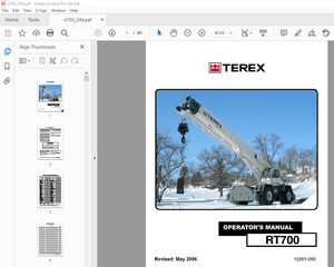
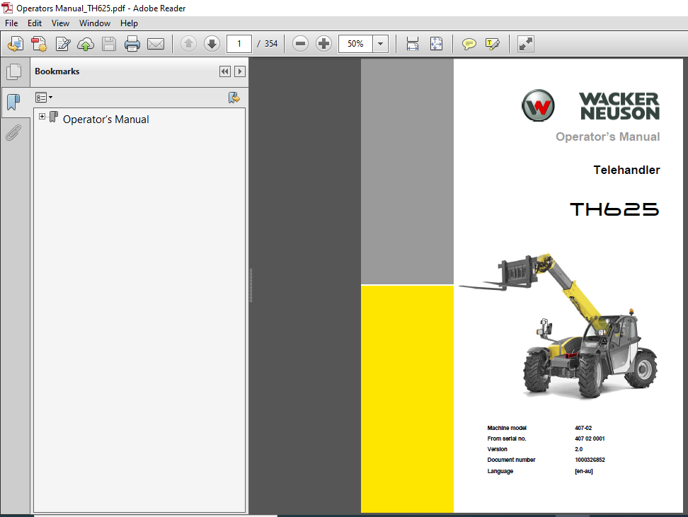
Wacker Neuson Telehandler TH625 Operator’s Manual
FILE DETAILS:
Wacker Neuson Telehandler TH625 Operator’s Manual
Language : English
Pages : 354
Downloadable : YES
Format : PDF
Size : 32.9 MB
DESCRIPTION:
Wacker Neuson Telehandler TH625 Operator’s Manual
Foreword :
Operator’s Manual:
- This Operator’s Manual applies to the model 407-02 telehandler and is only intended for use by the operator. It provides instructions on the use, the adjustment, the operation and the maintenance of the machine. Before driving or using the machine for the first time, the user must be briefed on this machine and must carefully read and understand this Operator’s Manual, in particular chapter “Safety instructions”.
- Work on the machine may only be performed by trained and instructed personnel that has been authorized by the operating company. Any person involved in operation, inspection, maintenance, servicing, repair work or transport of the machine must read, understand and follow the complete instructions in the Operator’s Manual and in particular the safety instructions.
- The buyer/operator is responsible for the drivers’ training in safe working on and with the machine. recommends repeating training at regular intervals. The buyer/operating company is responsible for ensuring that any additional safety regulations applicable in the country of use of the machine are followed. The machine may only be operated by persons who are physically, mentally and professionally suited for this work. Persons under the influence of alcohol or drugs may not use the machine.The operator is the person operating and/or driving the machine.
- Before putting the machine into operation, the operator of the machine must ensure that it is in a perfect condition, and during operation he must pay attention to the regulations regarding operation.
- The operator is responsible for ensuring that the machine and its use do not constitute a risk.
- Before working with the machine, the operator must familiarize himself with all the control elements and their functions, and with the handling of the machine.
TABLE OF CONTENTS:
Wacker Neuson Telehandler TH625 Operator’s Manual
1 Foreword
11 Operator’s Manual 1-1
12 Warranty and liability 1-4
2 Safety
21 Safety symbols and signal words 2-1
22 Conduct and safety instructions 2-2
23 Qualification of operating and maintenance personnel 2-3
24 Operation 2-4
25 Lifting gear applications 2-8
26 Trailer operation 2-10
27 Attachment operation 2-11
28 Towing, loading and transporting 2-12
29 Maintenance 2-15
210 Measures for avoiding risks 2-18
3 Introduction
31 Machine overview 3-1
32 Brief description of machine 3-3
33 Information and regulations on use 3-5
34 Labels 3-13
4 Putting into operation
41 Cabin/control stand 4-1
42 Overview of control elements 4-31
43 Indicator lights and warning lights 4-36
44 Preparatory work 4-39
45 Starting and stopping the engine 4-47
5 Operation
51 Steering system 5-1
52 Accelerator actuation 5-7
53 Brakes 5-9
54 Travel operation 5-13
55 Differential lock 5-19
56 Lights/signalling system 5-20
57 Wiper/wash system 5-28
58 Heating, ventilation and air conditioning system 5-30
59 Operating hydraulics 5-32
510 Attachments 5-55
511 Work operation 5-80
512 Emergency lowering 5-107
513 Options 5-109
514 Putting out of operation/back into operation 5-122
515 Permanently putting out of operation 5-124
6 Transport
61 Towing the machine 6-1
62 Loading the machine 6-4
63 Transporting the machine 6-8
Table of contents
I-2 BA 407-02 en/au * 20 * BA_407_02_AU_v10_en_auIVZfm
Table of contents
7 Maintenance
71 Notice on maintenance 7-1
72 Maintenance overview 7-3
73 Fluids and lubricants 7-11
74 Maintenance accesses 7-15
75 Cleaning and maintenance 7-16
76 Lubrication work 7-21
77 Fuel system 7-30
78 Engine lubrication system 7-34
79 Cooling system 7-37
710 Air filter 7-42
711 V-belt/toothed belt 7-45
712 Hydraulic system 7-46
713 Electrical system 7-52
714 Heating, ventilation and air conditioning system 7-57
715 Washer system 7-62
716 Axles/travelling drive 7-63
717 Braking system 7-64
718 Tyres 7-66
719 Maintenance of attachments 7-69
720 Maintenance of options 7-70
721 Machine preservation 7-73
8 Troubleshooting
81 Diesel engine malfunctions 8-1
82 Drive malfunctions 8-4
83 Malfunctions of the hydraulic system 8-6
84 Malfunctions in the air conditioning system (option) 8-7
9 Technical data
91 Model and trade names 9-1
92 Engine 9-1
93 Travelling drive/axles 9-2
94 Brakes 9-3
95 Tyres 9-4
96 Steering system 9-4
97 Operating hydraulics 9-5
98 Electrical system 9-7
99 Tightening torques 9-10
910 Coolant 9-11
911 Noise emissions 9-11
912 Vibration 9-12
913 Weight 9-12
914 Payload/lift capacity/stability 9-13
915 Dimensions 9-17
Index
Index S-1
INDEX:
Abbreviations 1-3
Accelerator actuation 5-7
Accelerator pedal 5-7
Accelerator pedal lock 5-8
Accident prevention regulations 3-9
Additional control circuit 5-48, 5-51
Additional electrical functions 5-106
Additional equipment 5-109
Additional front/rear hydraulic control circuit 5-51
Adjusting the additional mirror on the right
(option) 4-11
Adjusting the left-hand mirror 4-9
Adjusting the right-hand mirror 4-10
Air conditioning 5-30, 5-31
Air filter 7-42
Air-suspension seat 4-16
Alternator 7-54, 9-10
Anticorrosion agents 7-17
Anticorrosion protection 7-16, 7-73
Area of obstructed vision 4-6, 4-8
Attachment
Overview 3-11
Safety 2-11
Attachment lights 5-106
Attachments from other manufacturers 5-69
Inspection plan 5-79
Quickhitch 5-69
Autohitch trailer coupling (option) 5-114
Automatic trailer coupling 5-109
Axles 7-63, 9-2
B
Backrest 4-13
Backrest adjustment 4-13
Backup warning system 5-27
Battery 2-19, 9-10
Battery master switch 4-19
Behaviour during thunderstorm 2-22
Biodegradable oils 7-14
Bleeding the fuel system and refuelling 2-19
Brake hose 5-121
Brake/inching pedal 5-9
Brakes 5-9, 5-10, 9-3
Braking system 7-64
Safety instructions 7-64
Brief description of machine 3-3
Bucket mode 5-40
C
Cabin 4-1, 4-2
Right-hand window 4-2
Calculation for attachments
from other manufacturers 5-77
Carrying passengers 2-6
Central lubrication system 7-27
Certified attachments 3-12
Checking/replacing the battery 7-53
Cleaning 2-22, 7-16
Inside the cabin 7-18
Motor and engine compartment 7-20
On the outside of the machine 7-19
Seat belt 7-18
Cleaning and maintenance 7-16
Compressed air 7-16
Compressed-air braking system 2-18
Conduct and safety instructions 2-2
control 3rd circuit changeover valve 5-36
control 3rd circuit quick couplers 5-46
control 3rd circuit quick couplers (additional) 5-47
Control circuit III changeover valve
For additional control circuit 5-47
Control circuits
3rd control circuit 5-46
3rd control circuit changeover valve
for additional control circuit 5-47
Additional control circuit 5-51
Continuous operation of 3rd control circuit 5-49
Tipping trailer 5-118
Control elements 4-31
Control lever 4-35, 4-46, 5-36
Control stand 4-1
Control valve 9-5
Coolant 7-13, 9-11
Coolant preheating 4-28
Cooling system 3-4, 7-37
Crab steering 5-6
Crane-lifting 2-13, 6-6
Index
S-2 BA 407-02 en/au * 20 * BA_407_02_AU_v10_en_auSIXfm
Index
D
Danger zone 2-5
Description of machine 3-3
Designated use 3-6
Diagonal steering 5-6
Differential lock 5-19, 5-36
Digging 5-92, 5-93
Dimensions 9-17, 9-18
Disabling the travel direction 5-36
Displacement 9-5
Disposal 5-124
Documents 3-9
Door 4-2
Drawbar load 9-13
Drive 7-63, 9-2
Drive interlock 4-21
Drive interlock with code input (option) 4-24
Driving licence 3-8
Driving the machine 5-13
E
EC Declaration of Conformity EG-1
Electrical components 9-10
Electrical system 2-18, 9-7
Emergency exit – emergency hammer 4-4
Emergency hammer 4-4
Emergency lowering 5-107
Engine 4-47, 9-1
Starting 2-6, 4-47
Stopping 2-7, 4-51
Engine cover lock 7-15
Exhaust turbocharger 4-48
Explanation of symbols 1-3
External starting aid 4-50
F
Fastening, guiding and removing loads 2-8
Field of application of standard bucket 5-62
Field of vision 4-6, 4-7
Field of vision during work operation 4-1
Fields of application 3-11
Fields of application of pallet forks 5-67
Fire extinguisher 4-20
Fire hazard 2-20
Fitting and removing
Attachments from other manufacturers 5-69
Fluids 7-11
FOPS 4-1
Fork-lift mode 5-41
four wheel steering 3-4, 5-5
Front axle 9-3
Front axle steering 5-4
Front hydraulic connections 5-54
Front leak oil line 5-54
Front quick couplers 5-54
Front socket 5-106
Front wiper 5-28
Front/rear gross axle weight rating 9-12
Front-edge protection 4-44
Fuel preheater 4-29
Fuel system
Bleeding 7-33
Functional check
Brakes 4-46
Lights 4-46
Steering system 4-46
Fuse assignment 9-7
G
Grading 5-93
Grease 2-20
H
Hazard warning system 5-25
Headlight flasher 5-21
Heated seat 4-15
Heating 5-30
High beam 5-21
High-pressure cleaner 7-17
Horizontal suspension 4-14
Horn 5-25
Hose burst valve 5-81
Hydraulic attachment 5-46
Hydraulic lock 5-56
Hydraulic oil and coolant preheating 4-28
Hydraulic oil filter 9-5
Hydraulic pump 9-5
Hydraulic ram protection 9-5
Hydraulic system 2-18
3rd control circuit 5-36, 5-45, 5-46, 5-64
Hydrostatic drive 3-3
I
Identification 3-8
Ignition key 4-21, 4-49
Illumination 5-22
Important information on the cabin 4-1
Improper use 3-7
Inching 5-9
Indicating instrument 4-34
Indicator lights 4-34
Information and regulations on use 3-5
Inside the cabin 4-32
Instrument panel 4-34
Instrument panel (left) 4-34
Interior light 5-24
J
Job site 2-5
Joystick 4-35, 4-46, 5-36
K
Kerb weight 9-12
Key-based system 4-21
Keys 4-2
BA 407-02 en/au * 20 * BA_407_02_AU_v10_en_auSIXfm S-3
Index
L
Label
Battery master switch 3-22
Control elements on control lever 3-24
Drawbar load 3-25
Emergency exit 3-25
Ensuring machine stability 3-21
Filler opening for hydraulic oil 3-25
Fuel filler opening 3-23
Load diagram 3-24
Maximum machine speed 3-23
Noise levels 3-25
Tie down points 3-23
Tie-down points 3-23
Tyre pressure table 3-24
Labels 3-13, 3-23
Front of machine 3-15
Left-hand side of machine 3-13
Rear of machine 3-16
Right-hand side of machine 3-14
Lap belt 4-17
Lift capacity 9-13
Lift ram 9-5, 9-6
Lifting gear applications 2-8, 2-9
Lights 5-20
Limited field of vision 4-6, 4-8
Load 5-88, 5-99
Load diagram 5-88, 5-99
Load diagrams with pallet forks 9-14
Load stabilizer 5-86
Load table with bucket 9-16
Load transport 5-96
Loader unit
Spraying oil onto the slide plates 7-25
Loader unit attachments 5-55
Loading 5-90, 5-93
Low accesses 5-26
Low beam 5-20
Low-load operation 4-51
Low-speed control 5-18
Lubricants 7-11
Lubrication plan label 7-10
Lubrication points
Planetary drive bearing of axle 7-21
Rear axle oscillation-type bearing 7-21
Telescopic boom 7-22
Lubrication work 7-21
Lumbar support 4-14
M
Machine
Crane-lifting 6-7
Loading on a transport vehicle 6-4
Park 5-17
Stopping 5-16, 5-17
Stopping and securing 2-7
Towing 6-1
Transport 6-8
Tying down 6-8
Machine fuses 7-15
Machine inspections 3-9
Machine keys 4-2
Machine lights 5-20
Machine operation 2-6, 3-5
Machine overview 3-1
Machine preservation 7-73
Machine speed 5-7
Machine travel on public roads 2-7, 4-43, 4-44, 5-82
Main components of machine 3-3
Main fuse box 9-8
Maintenance 2-15, 7-1, 7-16
Adding coolant 7-40
Adding engine oil 7-36
Adding hydraulic oil 7-49
Air filter cartridge 7-44
Anticorrosive protection 7-74
Attachments 7-69
Axles/travelling drive 7-63
Braking system 7-64
Changing wheels 7-67
Checking the coolant level 7-39
Checking the engine oil level 7-35
Checking the hydraulic oil level 7-48
Electrical system 7-52
Engine and hydraulics cooling system 7-37
Engine lubrication system 7-34
Fuel system 7-30
Heating 7-57
Hydraulic pressure lines 7-50
Hydraulic system 7-46
Options 7-70
Pivots and hinges 7-20
Requirements 7-1
Responsibilities 7-1
Safety instructions 7-1
Servicing and maintenance
at regular intervals 7-54
Slide plates 7-24
Threaded fittings 7-20
Trailer coupling 7-70, 7-72
Tyre care 7-66
V-belt 7-45
Washer system 7-62
Work description 7-3, 7-4, 7-5, 7-6, 7-7, 7-8
S-4 BA 407-02 en/au * 20 * BA_407_02_AU_v10_en_auSIXfm
Index
Maintenance “Aggressive Media” 7-73
Maintenance accesses 7-15
Maintenance label 7-9
Maintenance overview 7-3
Maintenance plan 7-3
Malfunctions
Air conditioning 8-7
Diesel engine 8-1
Measures for avoiding risks 2-18
Measures for performing maintenance 2-16
Mechanical integrity 2-6
Mirror adjustment 4-9
Model designation 3-2
Modifications and spare parts 2-17
Multifunctional lever 4-35
N
Neutral 5-16, 5-36
Noise 2-22
Noise emissions 9-11
O
Oil 2-20
Operating hydraulics 3-4, 5-32, 9-5
Operation 5-1
Operator seat 4-12
Options 5-109
Other substances 2-20
Overload control 5-32, 5-38
Disabling 5-43
Overview
Control elements 4-31, 4-32
Inside the cabin 4-32
Instrument panel 4-34
Lubricants 7-11
Lubrication plan 7-9
Model and trade names 9-1
Overview of speed ranges 5-14
Owner’s duties 2-3
P
Pallet forks 5-67, 9-18
Adjusting the fork arms 5-101
Picking up loads 5-102
Transporting loads 5-103
Pallet forks transport position 5-95
Parking brake 5-11, 9-3
Payload 9-13
Permanently putting out of operation 5-124
Permissible maximum weight 9-12
Personal safety measures 2-15
Picking up a load 5-102
Preheating 4-28
Preheating start switch 4-49
Preparatory measures 2-16
Preparatory measures for the operator 2-3
Prerequisites for operation 2-2
Preserving the diesel engine 5-123
Pressure relief 5-63
Protective structures 2-17
Push-out ram 9-5, 9-6
Putting back into operation 5-122
Putting into operation 4-1
Putting out of operation 5-122
Putting the machine out of operation 5-123
Q
Qualifications 2-3
Quick coupler of hydraulic trailer brake 5-120
Quick couplers 5-63
Quick couplers of additional control circuit IV 5-51
Quickhitch 5-36, 5-45, 5-56, 5-68
With mechanical lock 5-57
Quickhitch ram (3rd control circuit) 9-5
Quickhitches 5-69
R
Rear axle 9-3
Rear mirrors (option) 4-11
Rear towing gear 5-80
Rear window heating 5-30
Rear wiper 5-28
Regulations on use 3-5
Removing and fitting attachments 2-11
Removing material 5-92, 5-93
Required knowledge of operator 2-3
Reservoir 5-29
Retracts/extends the telescopic boom 5-36
Reversing operation 5-16
Right-hand instrument panel 4-35
Right-hand window 4-5
Rotating beacon 5-26
BA 407-02 en/au * 20 * BA_407_02_AU_v10_en_auSIXfm S-5
Index
S
SAE grade 7-11, 7-12
Safe load indicator 5-32
Safe machine operation 3-5
Safety instructions
Attachment operation 2-11
Cooling system 7-37
For internal combustion engines 2-19
Lifting gear applications 2-8
Maintenance 2-15, 7-1
Operation 2-4
Towing, loading and transporting 2-12
Trailer operation 2-10
Working with a bucket 5-83
Safety prop for telescopic boom 7-2
Safety symbols 2-1
Screw dimensions 9-10
Seat adjustment 4-13
Seat belt 4-17
Adjustment 4-18
Seat suspension 4-15
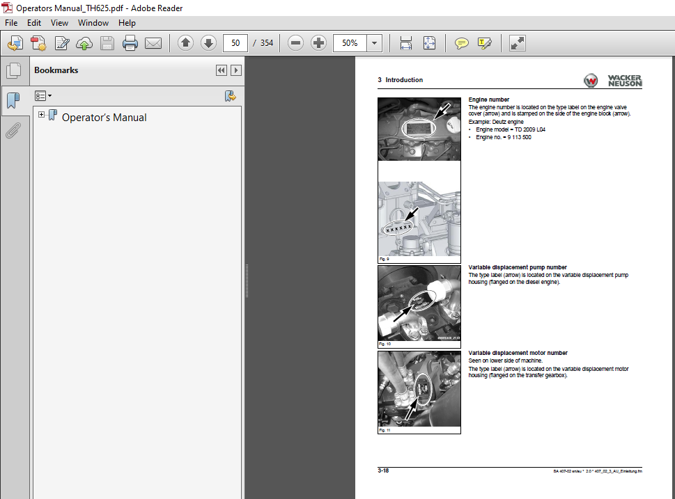
Serial number
Cabin number 3-17
Drive variable displacement motor 3-18
Drive variable displacement pump 3-18
Engine number 3-18
Front and rear axles 3-19
Gearbox (standard 20 kph) 3-19
Serial number 3-17
Service brake 5-9, 9-3
Setting down a load 5-104
Setting down loads 5-97
Setting engine speed 5-8
Side marker lights 5-20
Signal transmitter 5-27
Signal words 2-1
Signalling system 5-20
Slopes 5-17
Smart Handling 5-38
Specification 7-11, 7-12
Diesel fuel 7-13
Speed
Lift, tilt and push-out rams 9-6
Push-out ram 9-6
Tilt ram 9-6
Speed control 5-14
Stability 9-13
Stability calculation 5-73
Standard bucket 5-62
Start repeat interlock 4-47
Starter 9-10
Starting aid 4-50
Starting the engine 4-49
Steam jet 7-17
Steering column 5-1
Angle adjustment 5-1
Height adjustment 5-1
Steering modes 5-4
Steering system 5-1, 9-4
Synchronization 5-2
Switch console (left) 4-35
Switch console (right) 4-35
Switch console for rear attachments 4-35
Switching relay assignment 9-9
Symbols 3-17
IMAGES PREVIEW OF THE MANUAL
More products