$35
Wacker Neuson Track Excavator 1404 Service Manual_442188134 – PDF DOWNLOAD
Wacker Neuson Track Excavator 1404 Service Manual_442188134 – PDF DOWNLOAD
FILE DETAILS:
Wacker Neuson Track Excavator 1404 Service Manual_442188134 – PDF DOWNLOAD
Language : English
Pages :157
Downloadable : Yes
File Type : PDF
TABLE OF CONTENTS:
Wacker Neuson Track Excavator 1404 Service Manual_442188134 – PDF DOWNLOAD
Operation 1
Important information on this service manual 1-1
Abbreviations/symbols 1-1
Identification of warnings and dangers 1-2
Designated use and exemption from liability 1-3
Type labels and component numbers 1-4
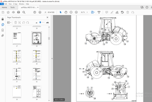
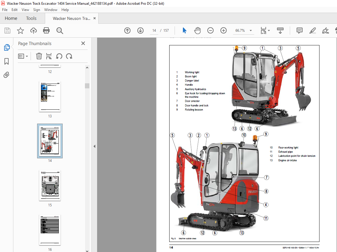
Machine overview 1-6
Cab overview 1-7
Cab overview: legend 1-8
Instrument panel overview 1-9
Instrument panel overview: legend 1-10
Engine compartment: overview 1-11
Chassis overview 1-12
Removing the cab 1-13
Removing the cab 1-14
Removing the floor panel 1-14
Battery master switch (model 1404) 1-14
Specifications 2
Chassis 2-1
Engine 2-1
Fuel injection pump 2-2
Engine capacities 2-2
Engine tightening torques 2-2
Hydraulic system 2-2
Auxiliary hydraulics oil flow 2-2
Work hydraulics 2-3
Undercarriage and swivel unit 2-3
Stabiliser blade 2-3
Electric system 2-3
Fuses on left-hand side control lever base 2-4
Main fuse box with relays 2-4
Noise levels 2-4
Vibration 2-5
Coolant compound table 2-5
Model-specific tightening torques 2-5
General tightening torques 2-6
Tightening torques for hydraulic screw connections (dry assembly) 2-6
Tightening torques for high-resistance screw connections 2-8
Dimensions model 1404 2-9
Lift capacity table 1404 RD 2-10
Lift capacity table 1404 RD with long stick (option) 2-11
Lift capacity table 1404 RD with cab (option) and telescopic undercarriage (option)
2-12
Lift capacity table 1404 RD with cab (option), long stick (option) and telescopic undercarriage
(option) 2-13
Kinematics 2-14
Attachments 2-15
Maintenance 3
Fluids and lubricants 3-1
Additional oil change and filter replacement (hydraulics) 3-2
Maintenance label 3-3
Explanation of symbols on the maintenance label 3-3
Maintenance plan (overview) 3-5
Table of contents
1-2 SERV-HB 1404 EN – Edition 11 * 140411IVZfm
Table of contents
Service package 3-8
Introduction 3-8
Fuel system 3-9
Specific safety instructions 3-9
Refuelling 3-9
Stationary fuel pumps 3-10
Diesel fuel specification 3-10
Bleeding the fuel system 3-10
Emptying the fuel tank 3-11
Fuel prefilter with water separator 3-12
Replacing the fuel filter 3-12
Engine lubrication system 3-13
Draining engine oil 3-14
Filling up engine oil 3-14
Changing engine oil 3-15
Replacing the engine oil filter cartridge 3-16
Engine cooling system 3-17
Specific safety instructions 3-17
Checking/filling up coolant 3-18
Draining coolant 3-19
Air filter 3-20
Air intake 3-20
Filter replacement 3-21
V-belt 3-22
Checking V-belt tension 3-22
Tightening the V-belt (dynamo) 3-23
Tightening the V-belt (alternator) 3-24
Pressure check 3-25
General 3-25
Checking pilot control pressure 3-25
Pressure check of gear pump P 3-26
Secondary pressure limiting valve of the gear motor 3-26
Test report 3-27
Hydraulic system 3-29
Specific safety instructions 3-29
Checking the hydraulic oil level 3-30
Filling up hydraulic oil 3-31
Changing hydraulic oil 3-31
Important information for the use of biodegradable oil 3-32
Checking hydraulic pressure lines 3-33
Pilot control filter (from serial number AF01441) 3-34
Travelling drive 3-35
Checking the oil level and filling up oil 3-35
Draining oil 3-35
Chains 3-36
Checking chain tension 3-36
Setting the chains 3-37
Lubrication work 3-38
Lubrication points on the stabiliser blade 3-38
Lubrication points on the swivelling console 3-38
Boom lubrication points 3-39
Lubrication points on the stick 3-39
Lubrication point for offset ram 3-39
Lubrication point on the live ring 3-40
Maintenance of attachments 3-40
Electric system 3-41
Specific safety instructions 3-41
SERV-HB 1404 EN – Edition 11 * 140411IVZfm 1-3
Table of contents
Service and maintenance work at regular intervals 3-41
Instructions concerning specific components 3-42
Alternator 3-42
Battery 3-43
General maintenance work 3-44
Cleaning 3-44
General instructions for all areas of the machine 3-44
Inside the cab 3-45
Cleaning the seat belt 3-45
Exterior of the machine 3-45
Engine compartment 3-45
Screw connections and attachments 3-46
Pivots and hinges 3-46
Engine 4
3TNV76-SNS2 engine overview 4-1
Fuel system 4-3
Checking and adjusting valve tip clearance 4-4
Tightening order for cylinder head bolts 4-4
Checking the injection nozzles 4-5
Pressure check 4-5
Checking the nozzle jet 4-5
Injection time 4-6
Checking and adjusting injection time 4-6
Replacement of fuel injection pump 4-7
Adjusting engine revs 4-8
Compression 4-8
Checking the coolant thermostat 4-8
Checking the thermal switch 4-9
Oil pressure switch 4-9
Checking the coolant circuit 4-10
Engine trouble 4-10
Hydraulic system 5
Gear pump AZPS-11-014RRR20MB 5-1
Pump unit: exploded view 5-2
Pilot oil supply unit 5-3
Main valve block SX 10 5-4
Ports 5-4
Legend 5-5
Sectional view 5-6
Functional description 5-6
Possible configurations 5-7
Main valve block diagram 5-8
Pressure limiting valves 5-9
Load sensing 5-10
Auxiliary hydraulics connections 5-10
Pilot valves 5-11
Joystick 5-11
Travelling drive 5-12
Function 5-12
Swivel unit 5-14
Swivel unit overview 5-18
Swivel joint 5-19
Sealing 5-20
Mechanical controls 5-20
Breather filter 5-22
1-4 SERV-HB 1404 EN – Edition 11 * 140411IVZfm
Table of contents
Troubleshooting in the hydraulic system 5-23
Hydraulics diagram A4 5-24
Hydraulics diagram: legend 5-25
Hydraulics diagram 1404 RD 5-27
Main valve block diagram 1404 RD 5-28
Electric system 6
Ohm’s Law (current, voltage, resistance); power 6-1
Measuring equipment, measuring methods 6-1
Cable colour coding 6-2
Relays 6-3
Use, mode of function 6-3
Electric system 6-3
Fuses on left-hand side control lever base 6-3
Main fuse box with relays 6-4
Instrument panel overview 6-4
Dynamo and governor 6-5
Starter 6-5
Wiring diagram A4 1404 RD: legend 6-7
Wiring diagram A4 1404 RD 6-8
Engine wiring harness 1404 RD: legend 6-9
Engine wiring harness A4 1404 RD 6-10
Seat console wiring harness A4 1404 RD: legend 6-11
Seat console wiring harness A4 1404 RD 6-13
Alternator wiring harness (option) A4 1404 RD 6-14
Wiring diagram A3 1404 RD: legend 6-16
Wiring diagram A3 1404 RD 6-17
Engine wiring harness A3 1404 RD: legend 6-18
Engine wiring harness A3 1404 RD 6-19
Seat console wiring harness A3 1404 RD: legend 6-20
Seat console and alternator wiring harness (option) A3 1404 RD 6-21
Options 7
Long stick 7-1
Specifications 7-1
Drive interlock (antitheft protection) 7-1
Position 7-1
Programming 7-1
IMAGES PREVIEW OF THE MANUAL:
More products