$38
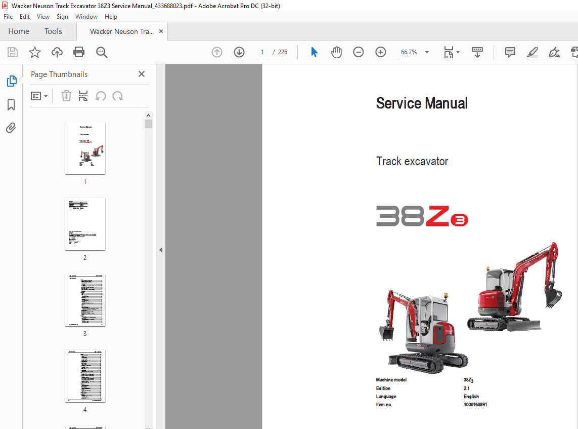
Wacker Neuson Track Excavator 38Z3 Service Manual_433688023 – PDF DOWNLOAD
Wacker Neuson Track Excavator 38Z3 Service Manual_433688023 – PDF DOWNLOAD
FILE DETAILS:
Wacker Neuson Track Excavator 38Z3 Service Manual_433688023 – PDF DOWNLOAD
Language : English
Pages :226
Downloadable : Yes
File Type : PDF
TABLE OF CONTENTS:
Wacker Neuson Track Excavator 38Z3 Service Manual_433688023 – PDF DOWNLOAD
Operation
Important information on this service manual 1-1
Identification of warnings and dangers 1-2
Designated use and exemption from liability 1-3
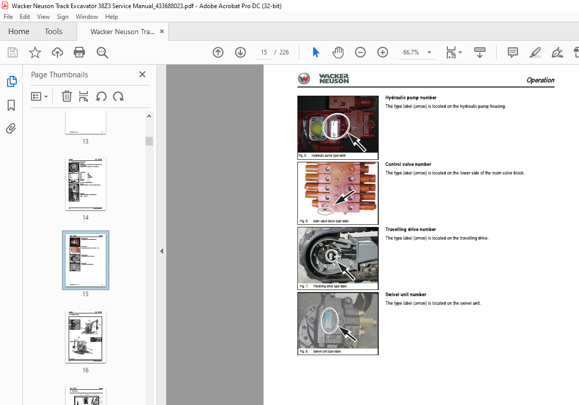
Type labels and component numbers 1-4
Machine: overview 1-6
Cab overview 1-7
Cab (legend) 1-8
Instrument panel overview (up to serial no AE02803) 1-9
Instrument panel (legend) 1-10
Instrument panel overview (from serial no AG00573) 1-11
Instrument panel (legend) 1-12
Engine compartment overview (Tier 2 up to AE02803) 1-13
Engine compartment overview (Tier 3A from AG00573) 1-14
Chassis overview 1-15
Tilting the cab 1-16
Specifications
Chassis 2-1
Engine 2-1
Fuel injection pump 2-2
Engine capacities 2-2
Engine tightening torques 2-2
Hydraulic system 2-3
Auxiliary hydraulics oil flow 2-3
Undercarriage and swivel unit 2-4
Stabiliser blade 2-4
Screwable hose burst valve 2-4
Electric system 2-5
Fuse box in instrument panel 2-5
Main fuse box with relays underneath the cab 2-5
Relays 2-6
Noise levels 2-6
Vibration 2-6
Coolant compound table 2-7
Model-specific tightening torques 2-7
General tightening torques 2-7
Tightening torques for hydraulic screw connections (dry assembly) 2-7
Tightening torques for high-resistance screw connections 2-9
Dimensions model 38Z3 2-11
Lift capacity table 38Z3 2-12
Lift capacity table 38Z3 short stick + extra weight 2-13
Lift capacity table 38Z3 long stick 2-14
Lift capacity table 38Z3 with long stick + extra weight 2-15
Kinematics 2-16
Attachments 2-17
Maintenance
Fluids and lubricants 3-1
Additional oil change and filter replacement (hydraulics) 3-2
Maintenance label 3-3
Explanation of symbols on the maintenance label 3-3
Maintenance plan (overview) 3-5
Service package 3-8
Up to serial no AE02803 3-8
From serial no AG00573 3-8
Table of contents
I-2 SERV-HB 38Z3 EN – Edition 21 * 38z3s2_1IVZfm
Table of contents
Introduction 3-8
Fuel system 3-9
Specific safety instructions 3-9
Refuelling 3-9
Stationary fuel pumps 3-10
Diesel fuel specification 3-10
Bleeding the fuel system 3-10
Emptying the fuel tank 3-11
Fuel prefilter with water separator 3-11
Replacing the fuel filter 3-12
Engine lubrication system 3-13
Checking the oil level 3-13
Filling up engine oil 3-14
Changing engine oil 3-15
Replacing the engine oil filter cartridge 3-16
Cooling system 3-17
Specific safety instructions 3-17
Checking/filling up coolant 3-18
Filling up coolant 3-19
Draining coolant 3-19
Air filter 3-20
Replacing the filter 3-21
Functional check once a week of the dust valve 3-22
V-belt 3-23
Checking V-belt tension 3-23
Retightening the V-belt 3-24
Checking the V-belt of the air conditioning system 3-25
Tightening the V-belt of the air conditioning system 3-26
Pressure check 3-27
General 3-27
Checking pilot control pressure 3-27
Pressure check of variable displacement pump P1 3-28
Pressure check of variable displacement pump P2 3-29
Pressure check of gear pump P3 3-30
Secondary pressure limiting valve of the gear motor 3-30
Measuring ports: overview 3-31
Primary pressure limiting valves 3-31
Test report 3-32
Hydraulic system 3-34
Specific safety instructions 3-34
Checking the hydraulic oil level 3-35
Filling up hydraulic oil 3-36
Changing hydraulic oil 3-36
Monitoring the hydraulic oil reflux filter 3-37
Checking hydraulic pressure lines 3-38
Travelling drive 3-39
Checking the oil level and filling up oil 3-39
Draining oil 3-39
Chains 3-40
Checking chain tension 3-40
Setting the chains 3-41
Lubrication work 3-42
Stabiliser blade 3-42
Lubrication points on the swivelling console 3-42
Boom lubrication points 3-43
Lubrication points on the stick 3-43
Lubrication strip 3-44
SERV-HB 38Z3 EN – Edition 21 * 38z3s2_1IVZfm I-3
Table of contents
Maintenance of attachments 3-44
Electric system 3-45
Specific safety instructions 3-45
Service and maintenance work at regular intervals 3-45
Instructions concerning specific components 3-46
Alternator 3-46
Battery 3-47
Cab 3-48
Replacing the cab filter 3-48
General maintenance work 3-49
Cleaning 3-49
General instructions for all areas of the machine 3-49
Inside the cab 3-50
Exterior of the machine 3-50
Engine compartment 3-50
Screw connections and attachments 3-50
Pivots and hinges 3-50
Engine
Engine overview 3TNV88-PNS (Tier 2) 4-1
Fuel system 4-3
Checking and adjusting valve tip clearance 4-4
Tightening order for cylinder head bolts 4-5
Checking the injection nozzles 4-6
Pressure check 4-6
Checking the nozzle jet 4-6
Injection time 4-7
Checking injection time 4-7
Setting injection time 4-8
Replacement of fuel injection pump 4-8
Adjusting engine revs 4-9
Compression 4-9
Checking the coolant thermostat 4-10
Checking the thermal switch 4-11
Oil pressure switch 4-11
Checking the coolant circuit 4-11
Engine overview 3TNV88-BPNS (Tier 3A) 4-12
Fuel system 4-14
Removing the cylinder-head cover 4-15
Checking and adjusting valve tip clearance 4-15
Tightening order for cylinder head bolts 4-16
Checking the injection nozzles 4-17
Pressure check 4-17
Checking the nozzle jet 4-17
Injection time 4-18
Checking injection time 4-18
Setting injection time 4-19
Replacement of fuel injection pump 4-20
Adjusting engine revs 4-21
Compression 4-21
Checking the coolant thermostat 4-21
Checking the thermal switch 4-22
Oil pressure switch 4-22
Checking the coolant circuit 4-23
Engine trouble 4-23
Hydraulic system
Hydraulic pump PVD-1B-32BP-11G5-4904A (up to AE02803)
I-4 SERV-HB 38Z3 EN – Edition 21 * 38z3s2_1IVZfm
Table of contents
PVD-1B-34BP-10G5 (from AG00573) 5-1
Pump unit: exploded view 5-3
Pilot oil supply unit 5-4
Main valve block 5-5
Ports 5-5
Legend 5-6
Main valve block diagram 5-7
Pressure limiting valves 5-8
Pump assignment 5-9
Drive counterbalancing system 5-10
Pump assignment for drive counterbalancing 5-10
Regeneration – stick section 5-11
Bucket pre-tension 5-11
Flow rate adjustment of auxiliary hydraulics 5-12
Pilot valves 5-13
Joystick 5-13
Pilot valve (driving) 5-15
Pilot valve for auxiliary hydraulics 5-17
Valves 5-18
7/2 directional valve (changeover valve) 5-18
Changeover valve for SAE/ISO controls (option) 5-19
Travelling drive up to no AE00854 5-20
Function 5-21
Travelling drive starting no AE00855 5-23
Function 5-24
Swivel unit 5-26
Parking brake/multidisc brake function 5-27
Swivel joint 5-30
Sealing 5-30
Breather filter 5-31
Troubleshooting in the hydraulic system 5-32
Hydraulics diagram A4 5-33
Hydraulics diagram (legend) 5-34
Hydraulics diagram 38Z3 A3 5-35
Option diagram 1 5-36
Option diagram 2 5-37
Main valve block diagram 38Z3 A3 5-38
Electric system
Ohm’s Law (current, voltage, resistance); power 6-1
Measuring equipment, measuring methods 6-1
Cable colour coding 6-3
Relays 6-3
Use, mode of function 6-3
Electric units 6-4
Fuse box in instrument panel 6-4
Main fuse box with relays 6-4
Relays 6-5
Socket 6-5
Joystick tip switches 6-6
Joystick (left) 6-6
Joystick (right) 6-6
Instrument panel overview 6-6
Switch overview (up to serial no AE02803) 6-7
Switch overview (from serial no AG00573) 6-8
Alternator 6-9
Starter 6-9
SERV-HB 38Z3 EN – Edition 21 * 38z3s2_1IVZfm I-5
Table of contents
Wiring diagram A4 38Z3 (legend) 6-11
Wiring diagram A4 6-12
Engine wiring harness (legend) 6-13
Engine wiring harness A4 6-14
Cab wiring harness A4 (legend) 6-15
Cab wiring harness A4 6-16
Roof wiring harness A4 6-17
Revs control wiring harness (option) 6-18
Wiring diagram A3 (legend) 6-20
Wiring diagram A3 6-21
Engine wiring harness A3 (legend) 6-22
Engine wiring harness A3 6-23
Cab wiring harness A3 (legend) 6-24
Cab wiring harness A3 6-25
Roof wiring harness A3 6-26
Revs control wiring harness (option) 6-27
Options
Air conditioning 7-3
Specific safety instructions 7-3
Specifications 7-3
Components 7-5
Compressor 7-6
Filling up the air conditioning system 7-7
Maintenance 7-8
Troubleshooting 7-9
Counterweight 7-10
Specifications 7-10
Long stick 7-10
Specifications 7-10
Control circuit (pipework) connections for grab 7-11
Attachments 7-11
3rd control circuit connections 7-12
Auxiliary hydraulics connections 7-12
Safe load indicator DE (safety valve for boom) 7-13
Position 7-13
Setting the pressure switch 7-13
Function 7-14
Wiring diagram 7-14
Safe load indicator FR (safety valves for boom and stick) 7-15
Position 7-15
Setting the pressure switch 7-15
Function 7-16
Wiring diagram 7-17
3rd control circuit 7-18
Function 7-18
Diagram 7-18
Drive interlock (antitheft protection) 7-19
Position 7-19
Disabling the drive interlock 7-19
Enabling the drive interlock 7-19
Programming 7-19
Proportional controls 7-21
Function 7-21
Ports 7-21
Overview 7-22
Wiring harness 7-23
I-6 SERV-HB 38Z3 EN – Edition 21 * 38z3s2_1IVZfm
Table of contents
Control valve plug assignment 7-24
Safety features 7-25
Measures to be taken in case of malfunctions 7-25
Diagnosis display 7-25
Fuel-filling pump 7-27
Connections 7-28
Service valve 7-29
Function 7-29
Automatic revs setting (Tier 3A from AG00573) 7-30
Installation 7-31
IMAGES PREVIEW OF THE MANUAL:

More products