$39
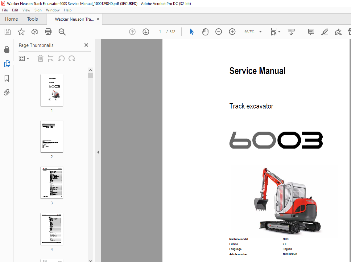
Wacker Neuson Track Excavator 6003 Service Manual_1000129840 – PDF DOWNLOAD
Wacker Neuson Track Excavator 6003 Service Manual_1000129840 – PDF DOWNLOAD
FILE DETAILS:
Wacker Neuson Track Excavator 6003 Service Manual_1000129840 – PDF DOWNLOAD
Language : English
Pages :342
Downloadable : Yes
File Type : PDF
TABLE OF CONTENTS:
Wacker Neuson Track Excavator 6003 Service Manual_1000129840 – PDF DOWNLOAD
Operation
Important information on this service manual 1-1
Identification of warnings and dangers 1-2
Designated use and exemption from liability 1-3
Type labels and component numbers 1-4
Machine overview 1-6
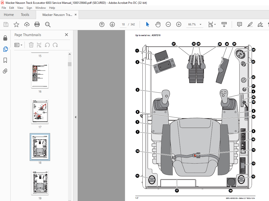
Cab overview 1-7
Up to serial no: AD07210 1-7
From serial no: AH00645 1-8
Cab (legend) 1-9
Instrument panel up to serial no AC02888: overview 1-10
Instrument panel up to serial no AC02888: legend 1-11
Instrument panel from serial no AC02890 to AD07210: overview 1-12
Instrument panel from serial no AC02890 to AD07210: legend 1-13
Instrument panel from serial no AH00645: overview 1-14
Instrument panel from serial no AH00645: legend 1-15
Engine compartment up to serial no AD07210: overview 1-16
Engine compartment from serial no AD00611: overview 1-17
Chassis overview 1-18
Tilting the cab 1-19
Summer/winter operation 1-21
Preheated fresh air 1-21
Auxiliary hydraulics/boom swivel pedal 1-22
Battery master switch 1-22
Specifications
Chassis 2-1
Engine 2-1
Fuel injection pump 2-2
Capacities 2-2
Tightening torques 2-2
Hydraulic system 2-3
Auxiliary hydraulics oil flow* 2-4
Screwable hose burst valve 2-4
Undercarriage and swivel unit 2-4
Stabiliser blade 2-4
Electric system 2-4
Fuse box on the instrument panel up to serial no AD07210 2-5
Main fuse box with relays under the cab up to serial no AD07210 2-5
Relays up to serial no AD07210 2-5
Fuse box on the instrument panel from serial no AH00645 2-6
Main fuse box with relays from serial no AH00645 2-6
Noise levels 2-7
Vibration 2-7
Coolant compound table 2-7
Model-specific tightening torques 2-8
General tightening torques 2-8
Tightening torques for hydraulic screw connections (dry assembly) 2-8
Tightening torques for high-resistance screw connections 2-10
Dimensions model 6003 2-11
Lift capacity table 6003 2-12
Lift capacity table 6003 with long stick option 2-13
Lift capacity table 6003 with counterweight option 2-14
Lift capacity table 6003 with long stick and counterweight 2-15
Lift capacity table 6003 Vario 2-16
Table of contents
I-2 SERV-HB 6003 EN – Edition 20 * 6003s2_0IVZfm
Table of contents
Kinematics 2-17
Attachments 2-18
Maintenance
Fluids and lubricants 3-1
Additional oil change and filter replacement (hydraulics) 3-2
Maintenance label 3-3
Explanation of symbols on the maintenance label 3-3
Maintenance plan (overview) 3-5
Service package 3-8
Up to serial no AD07210 3-8
From serial no AH00645 3-8
Introduction 3-8
Fuel system 3-9
Specific safety instructions 3-9
Refuelling 3-9
Stationary fuel pumps 3-10
Diesel fuel specification 3-10
Bleeding the fuel system 3-10
Emptying the fuel tank 3-11
Fuel prefilter with water separator 3-11
Replacing the fuel filter 3-12
Engine lubrication system 3-13
Checking the oil level 3-13
Filling up engine oil 3-14
Changing engine oil 3-15
Replacing the engine oil filter cartridge 3-16
Cooling system 3-17
Specific safety instructions 3-17
Checking/filling up coolant 3-18
Draining coolant 3-19
Air filter 3-20
Replacing the filter 3-21
Functional check once a week of the dust valve 3-22
V-belt 3-23
Checking V-belt tension 3-23
Retightening the V-belt 3-24
Checking the V-belt of the air conditioning system 3-25
Tightening the V-belt of the air conditioning system 3-25
Pressure check 3-26
General 3-26
Checking pilot control pressure 3-26
Pressure check of variable displacement pump P1 3-27
Pressure check of variable displacement pump P2 3-28
Pressure check of gear pump P3 3-29
Secondary pressure limiting valve of the gear motor 3-30
Measuring ports: overview 3-30
Primary pressure limiting valves 3-30
Test report 3-31
Hydraulic system 3-34
Specific safety instructions 3-34
Checking the hydraulic oil level 3-35
Filling up hydraulic oil 3-36
Changing hydraulic oil 3-37
Monitoring the hydraulic oil reflux filter 3-37
Checking hydraulic pressure lines 3-38
SERV-HB 6003 EN – Edition 20 * 6003s2_0IVZfm I-3
Table of contents
Travelling drive 3-38
Checking the oil level and filling up oil 3-39
Draining oil 3-39
Chains 3-40
Checking chain tension 3-40
Setting the chains 3-41
Lubrication work 3-42
Stabiliser blade 3-42
Lubrication points on the swivelling console 3-42
Boom lubrication points 3-43
Lubrication points on the stick 3-43
Lubrication strip 3-44
Maintenance of attachments 3-44
Electric system 3-45
Specific safety instructions 3-45
Service and maintenance work at regular intervals 3-45
Instructions concerning specific components 3-46
Alternator 3-46
Battery 3-47
Jump-starting the engine 3-47
Cab 3-48
Replacing the cab filter 3-48
General maintenance work 3-49
Cleaning 3-49
General instructions for all areas of the machine 3-49
Inside the cab 3-50
Exterior of the machine 3-50
Engine compartment 3-50
Screw connections and attachments 3-50
Pivots and hinges 3-50
Engine
Engine 4TNV98-VNS (Tier 2 up to serial no AD07210) 4-1
Fuel system 4-3
Removing the valve cover 4-4
Checking and adjusting valve clearance 4-4
Checking valve clearance 4-4
Setting zero play of the valve bridge 4-5
Setting valve clearance 4-5
Tightening order for cylinder head bolts 4-6
Checking the injection nozzles 4-7
Pressure check 4-7
Checking the nozzle jet 4-7
Injection time 4-8
Checking injection time 4-8
Setting injection time 4-8
Replacement of fuel injection pump 4-9
Adjusting engine revs 4-10
Compression 4-10
Checking the coolant thermostat 4-11
Checking the thermal switch 4-11
Oil pressure switch 4-12
Checking the coolant circuit 4-12
Engine 4TNV98-ZVNS from serial no AH00645 4-13
Fuel system 4-15
Removing the valve cover 4-16
I-4 SERV-HB 6003 EN – Edition 20 * 6003s2_0IVZfm
Table of contents
Checking and adjusting valve clearance 4-16
Checking valve clearance 4-16
Setting zero play of the valve bridge 4-17
Setting valve clearance 4-17
Tightening order for cylinder head bolts 4-18
Checking the injection nozzles 4-19
Pressure check 4-19
Checking the nozzle jet 4-19
Injection time 4-20
Checking injection time 4-20
Setting injection time 4-21
Replacement of fuel injection pump 4-22
Compression 4-23
Checking the coolant thermostat 4-23
Checking the thermal switch 4-24
Oil pressure switch 4-24
Checking the coolant circuit 4-24
Engine trouble 4-25
Electronic engine control unit (E-ECU) 4-27
Features 4-27
Engine error codes 4-28
Error diagnosis 4-32
E-ECU connector assignment 4-32
Important information on the ECU maintenance wiring harness 4-33
Flash code 7 – proportional injection pump solenoid (control rack) 4-34
Related DTC (Diagnostic Trouble Codes) 4-34
Diagnosis description 4-36
Flash code 5 – manual throttle 4-38
Related DTC 4-38
Work description 4-40
Flash code 4-1 ECU internal 4-41
Related DTC 4-41
Work description 4-42
Flash code 4-1 ECU temperature sensor and 2-5 ECU temperature rise alarm
4-43
Related DTC 4-43
Work description 4-44
Flash code 4 coolant temperature sensor and 3-6 coolant temperature rise alarm
4-45
Related DTC 4-45
Work description 4-47
Flash code 2-4 – sensor 5 V 4-49
Related DTC 4-49
Work description 4-50
Flash code 2-3 – power supply voltage 4-52
(1) P0562/1: power supply voltage error (voltage too low) 4-52
DTC detection conditions 4-52
Troubleshooting 4-52
Diagnosis description 4-52
(2) P0563/0: power supply voltage error (voltage too high) 4-53
DTC detection conditions 4-53
Troubleshooting 4-53
Diagnosis description 4-53
Flash code 6 – revs sensor 4-54
Work description 4-56
Flash code 1-1 – backup revs sensor 4-57
Related DTC 4-57
SERV-HB 6003 EN – Edition 20 * 6003s2_0IVZfm I-5
Table of contents
Work description 4-59
Flash code 9 – overspeed error 4-60
(1) P0219/0: overspeed error 4-60
DTC detection conditions 4-60
Troubleshooting 4-60
Diagnosis description 4-60
Flash code 1-7 – proportional solenoid relay of the injection pump (control rack)
4-61
Related DTC 4-61
Work description 4-63
Flash code 1-5 – preheating relay 4-65
Related DTC 4-65
Work description 4-66
Flash code 1-4 – CSD (cold start device) solenoid coil 4-69
Related DTC 4-69
Work description 4-70
Flash code 1-3 – EGR (exhaust gas recirculation) valve 4-72
Related DTC 4-72
Work description 4-74
Flash code 2-1 – oil pressure switch and 3-1 – oil pressure drop error 4-76
Related DTC 4-76
Work description 4-78
Flash code 8 – proportional injection pump solenoid (control rack) 4-80
Related DTC 4-80
Work description 4-82
Flash code 1-6 – main relay 4-84
Related DTC 4-84
Work description 4-86
Flash code 1-2 – CAN (Controller Area Network) communication 4-88
Related DTC 4-88
Work description 4-89
Automatic revs setting 4-90
How it works 4-90
Hydraulic system
Hydraulic pump PVD-3B-56P-21G5-4626F 5-1
Pump unit: exploded view 5-3
Pilot oil supply unit 5-5
Main valve block with 3rd control circuit and triple articulation boom 5-6
Ports 5-6
Legend 5-7
Main valve block diagram 5-8
Pressure limiting valves 5-9
Pump assignment 5-10
Drive counterbalancing system 5-11
Pump assignment for drive counterbalancing 5-11
Drive counterbalancing diagram 5-12
Regeneration – stick section 5-13
Bucket pre-tension 5-13
Boom summation – raise 5-14
Check valve (load retaining valve) 5-15
Flow rate adjustment of auxiliary hydraulics 5-16
Pilot valves 5-17
Joystick 5-17
Pilot valve (driving) 5-19
Pilot valve for auxiliary hydraulics 5-21
Pilot valve for stabiliser blade 5-22
I-6 SERV-HB 6003 EN – Edition 20 * 6003s2_0IVZfm
Table of contents
Valves 5-23
7/2 directional valve (changeover valve) 5-23
4/3 directional valve 5-24
Shuttle valve block 5-25
Changeover valve for SAE/ISO controls (option) 5-26
Travelling drive 5-27
Function 5-28
2nd speed range function 5-28
Swivel unit 5-31
Parking brake/multidisc brake function 5-32
Swivel joint 5-37
Breather filter 5-38
Troubleshooting in the hydraulic system 5-39
Hydraulics diagram A4 5-40
Hydraulics diagram (legend) 5-41
Hydraulics diagram A3 5-42
Options diagrams 1 (from serial no AC04070) 5-43
Options diagrams 2 (from serial no AC04070) 5-44
Main valve block A3 diagram 5-45
Electric system
Ohm’s Law (current, voltage, resistance); power 6-1
Measuring equipment, measuring methods 6-1
Cable colour coding 6-2
Relays 6-2
Use, mode of function 6-2
Electric units 6-3
Fuse box on the instrument panel up to serial no AD07210 6-3
Main fuse box with relays up to serial no AD07210 6-3
Relays 6-4
Fuse box on the instrument panel from serial no AH00645 6-4
Main fuse box with relays from serial no AH00645 6-5
ECU from serial no AH00645 6-5
Socket 6-6
Joystick tip switches 6-6
Joystick (left) 6-6
Joystick (right) 6-6
Instrument panel overview 6-7
Switches: overview 6-8
Alternator 6-8
Starter 6-8
Wiring diagram A4 up to serial no AC02888 (legend) 6-10
Wiring diagram A4 up to serial no AC02888 6-11
Wiring diagram A4 from serial no AC02890 (legend) 6-12
Wiring diagram A4 from serial no AC02890 6-13
Wiring diagram A4 from serial no AH00645 (legend) 6-14
Wiring diagram A4 (1) from serial no AH00645 6-15
Wiring diagram A4 (2) from serial no AH00645 6-16
Engine – chassis A4 wiring harness 1000109624 up to AD07210 (legend) 6-17
Engine – chassis A4 wiring harness 1000109624 up to AD07210 6-18
Engine – chassis A4 wiring harness 1000173970 from AH00645 (legend) 6-19
Engine – chassis A4 wiring harness 1000173970 from AH00645 6-20
Switches A4 wiring harness 1000109630 up to serial no AC02888 (legend) 6-21
Switches A4 wiring harness 1000109630 up to serial no AC02888 6-22
Switches A4 wiring harness from serial no AC02890 (legend) 6-23
Switches A4 wiring harness from serial no AC02890 6-24
Wiring harness 1000109629: cab roof 6-25
SERV-HB 6003 EN – Edition 20 * 6003s2_0IVZfm I-7
Table of contents
Wiring harness 1000109628: armrest 6-26
Wiring harness 1000116138: boom working light 6-27
Wiring diagram A3 up to serial no AC02888 (legend) 6-29
Wiring diagram A3 up to serial no AC02888 6-30
Wiring diagram A3 from serial no AC02890 – AD07210 (legend) 6-31
Wiring diagram A3 from serial no AC02890 – AD07210 6-32
Wiring diagram A4 from serial no AH00645 (legend) 6-33
Wiring diagram A4 (1) from serial no AH00645 6-34
Wiring diagram A4 (2) from serial no AH00645 6-35
Engine – chassis A3 wiring harness 1000109624 (legend) 6-36
Engine – chassis A3 wiring harness 1000109624 6-37
Engine – chassis A3 wiring harness 1000173970 from serial no AH00611 (legend)
6-38
Engine – chassis A3 wiring harness 1000173970 from serial no AH00611 6-39
Switches A3 wiring harness 1000109630 up to serial no AC02888 (legend) 6-40
Switches A3 wiring harness 1000109630 up to serial no AC02888 6-41
Switches A3 wiring harness from serial no AC02890 (legend) 6-42
Switches A3 wiring harness from serial no AC02890 6-43
Wiring harness 1000109629: cab roof A3 6-44
Wiring harness 1000109628: armrest A3 6-45
Wiring harness 1000116138: boom working light A3 6-46
Options
Air conditioning 7-1
Specific safety instructions 7-1
Specifications 7-1
Installation: overview 7-2
Components 7-3
Filling up the air conditioning system 7-5
Maintenance 7-6
Troubleshooting 7-7
Air-suspension seat 7-9
Ports 7-9
Counterweight 7-9
Specifications 7-9
Long stick 7-9
Specifications 7-9
Control circuit (pipework) connections for grab 7-10
3rd control circuit connections 7-10
Auxiliary hydraulics connections 7-11
Quickhitch couplings 7-11
Attachments 7-12
Neuson Vario 7-13
Using the Neuson Vario feature 7-13
Vario diagram 7-14
Function 7-14
Neuson Vario warning device 7-15
Ports 7-16
Fuel-filling pump 7-17
Connections up to serial no AD07210 7-18
Central lubrication system 7-19
Position 7-19
Connections 7-19
Function 7-20
Adjusting breaks and lubrication times 7-21
Repair in case of clogging 7-21
I-8 SERV-HB 6003 EN – Edition 20 * 6003s2_0IVZfm
Table of contents
Service valve 7-23
Function 7-23
Safe load indicator D (safety valve for boom) 7-24
Position 7-24
Function 7-24
Diagram 7-25
Safe load indicator F (safety valves for boom and stick) 7-26
Position 7-26
Function 7-27
Diagram 7-28
3rd control circuit 7-29
Function 7-29
Diagram 7-30
Triple articulation boom 7-31
Function 7-31
Diagram 7-32
Electric auxiliary hydraulics 7-33
Function 7-33
Auxiliary hydraulics shock cartridge 7-35
3rd control circuit shock cartridge 7-36
Drive interlock (antitheft protection) 7-37
Position 7-37
Disabling the drive interlock 7-37
Enabling the drive interlock 7-37
Programming 7-37
Quickhitch 7-39
Proportional controls 7-40
Function 7-40
Ports 7-40
Overview of auxiliary hydraulics controls 7-41
Hammer operation 7-41
Adjusting control response 7-41
Characteristic curve – status display 7-41
Wiring harness 7-42
Control unit 7-42
Control valve plug assignment 7-43
Safety features 7-44
Measures to be taken in case of malfunctions 7-44
Diagnosis display 7-44
IMAGES PREVIEW OF THE MANUAL:
More products