$39
Wacker Neuson Track Excavator 8003 Service Manual_1000132826 -PDF DOWNLOAD
Wacker Neuson Track Excavator 8003 Service Manual_1000132826 -PDF DOWNLOAD
FILE DETAILS:
Wacker Neuson Track Excavator 8003 Service Manual_1000132826 -PDF DOWNLOAD
Language : English
Pages :329
Downloadable : Yes
File Type : PDF
TABLE OF CONTENTS:
Wacker Neuson Track Excavator 8003 Service Manual_1000132826 -PDF DOWNLOAD
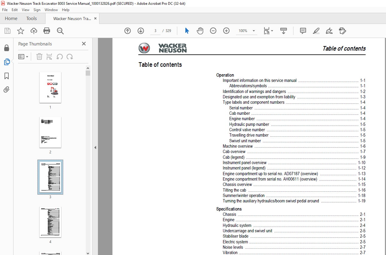
Operation
Important information on this service manual 1-1
Abbreviations/symbols 1-1
Identification of warnings and dangers 1-2
Designated use and exemption from liability 1-3
Type labels and component numbers 1-4
Serial number 1-4
Cab number 1-4
Engine number 1-4
Hydraulic pump number 1-5
Control valve number 1-5
Travelling drive number 1-5
Swivel unit number 1-5
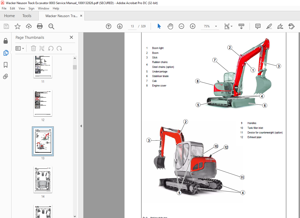
Machine overview 1-6
Cab overview 1-7
Cab (legend) 1-9
Instrument panel overview 1-10
Instrument panel (legend) 1-12
Engine compartment up to serial no AD07187 (overview) 1-13
Engine compartment from serial no AH00611 (overview) 1-14
Chassis overview 1-15
Tilting the cab 1-16
Summer/winter operation 1-18
Turning the auxiliary hydraulics/boom swivel pedal around 1-19
Specifications
Chassis 2-1
Engine 2-1
Hydraulic system 2-4
Undercarriage and swivel unit 2-5
Stabiliser blade 2-5
Electric system 2-5
Noise levels 2-7
Vibration 2-7
Coolant compound table 2-8
Model-specific tightening torques 2-8
General tightening torques 2-8
Dimensions model 8003 2-13
Lift capacity table 8003 2-14
Lift capacity table 8003 with long stick 2-15
Lift capacity table 8003 with counterweight 2-16
Lift capacity table 8003 with long stick and counterweight 2-17
Lift capacity table 8003 Vario (option) 2-18
Kinematics 2-19
Maintenance
Fluids and lubricants 3-1
Maintenance label 3-3
Maintenance plan (overview) 3-5
Service package 3-9
Introduction 3-9
Fuel system 3-10
General 3-11
Refuelling from barrels 3-11
Engine lubrication system 3-14
Checking the oil level 3-14
Table of contents
I-2 SERV-HB 8003 EN – Edition 20 * 8003s11IVZfm
Table of contents
Cooling system 3-18
Checking the coolant level 3-19
Filling up coolant 3-20
Air filter 3-21
V-belt 3-24
Pressure check 3-27
Test report 3-32
Hydraulic system 3-35
Travelling drive 3-40
Chains 3-41
Lubrication work 3-43
Electric system 3-46
Cab 3-49
General maintenance work 3-50
When using washing solvents 3-50
When using compressed air 3-50
When using a high-pressure cleaner or steam jet 3-50
When using volatile and easily flammable anticorrosion agents and sprays: 3-50
Cleaning the seat belt: 3-51
Engine
Engine 4TNV98-VNS (up to serial no AD07187 American Tier 2) 4-1
Fuel system 4-3
Removing the valve cover 4-4
Checking and adjusting valve clearance 4-4
Tightening order for cylinder head bolts 4-6
Checking the injection nozzles 4-7
Checking the nozzle jet 4-7
Injection time 4-8
Adjusting engine revs 4-10
Compression 4-10
Checking the coolant thermostat 4-10
Checking the thermal switch 4-11
Oil pressure switch 4-11
Checking the coolant circuit 4-12
Engine 4TNV98-ZVNS from serial no AH00611 4-13
Fuel system 4-15
Removing the valve cover 4-16
Checking and adjusting valve clearance 4-16
Tightening order for cylinder head bolts 4-18
Checking the injection nozzles 4-19
Checking the nozzle jet 4-19
Injection time 4-20
Compression 4-23
Checking the coolant thermostat 4-23
Checking the thermal switch 4-24
Oil pressure switch 4-24
Checking the coolant circuit 4-24
Engine trouble 4-25
Electronic engine control (E-ECU) 4-27
Engine error codes 4-28
Error diagnosis 4-32
Automatic revs setting 4-90
Automatic revs setting enabled 4-90
Hydraulic system
Hydraulic pump AP2D36LV3RS6-874-P 5-1
Main valve block 5-6
SERV-HB 8003 EN – Edition 20 * 8003s11IVZfm I-3
Table of contents
Drive counterbalancing system 5-13
Boom raise summation 5-15
Boom check valve (load retaining valve) 5-16
Stick ram summation 5-17
Stick check valve (load retaining valve) 5-18
Pilot valves 5-19
Valves 5-25
Pressure cutoff valve 5-27
Travelling drive up to serial no AC 02956 5-32
Auto2Speed drive from serial no AC 02957 5-34
Swivel unit 5-37
Swivel joint 5-43
Breather filter 5-44
Troubleshooting in the hydraulic system 5-45
Hydraulics diagram A4 5-46
Hydraulics diagram (legend) 5-47
Hydraulics diagram 5-48
Options diagram 1 5-49
Options diagram 2 5-50
Main valve block diagram 5-51
Electric system
Ohm’s Law (current, voltage, resistance); power 6-1
Measuring equipment, measuring methods 6-1
Cable colour coding 6-3
Relays 6-3
Electric units 6-4
Fuse box on the instrument panel up to serial no AD07187 6-4
Main fuse box with relays up to serial no AD07187 6-4
Relays up to serial no AD07187 6-5
Fuse box on the instrument panel from serial no AH00611 6-5
Main fuse box with relays from serial no AH00611 6-6
ECU from serial no AH00611 6-7
Socket 6-7
Joystick tip switches 6-8
Instrument panel overview 6-9
Switches: overview 6-10
Alternator 6-11
Starter 6-11
Wiring diagram A4 up to serial no AD07187 (legend) 6-13
Wiring diagram A4 up to serial no AD07187 6-14
Wiring diagram A4 from serial no AH00611 (legend) 6-15
Wiring diagram A4 (1) from serial no AH00611 6-16
Wiring diagram A4 (2) from serial no AH00611 6-17
Engine – chassis A4 wiring harness 1000116497 up to serial no AD07187 (legend)
6-18
Engine – chassis A4 wiring harness 1000116497 up to serial no AD07187 6-19
Engine – chassis A4 wiring harness 1000173970 from serial no AH00611 (legend)
6-20
Engine – chassis A4 wiring harness 1000173970 from serial no AH00611 6-21
Wiring harness 1000125106 switches A4 (legend) 6-22
Wiring harness 1000125106 switches A4 6-23
Wiring harness 1000109629: cab roof 6-24
Wiring harness 1000109628: armrest 6-25
Wiring harness 1000116138: boom working light 6-26
Wiring diagram A3 up to serial no AD07187 (legend) 6-29
Wiring diagram A3 up to serial no AD07187 6-30
I-4 SERV-HB 8003 EN – Edition 20 * 8003s11IVZfm
Table of contents
Wiring diagram A4 from serial no AH00611 (legend) 6-31
Wiring diagram A4 (1) from serial no AH00611 6-32
Wiring diagram A4 (2) from serial no AH00611 6-33
Engine – chassis A3 wiring harness 1000109624 up to serial no AD07187 (legend)
Engine – chassis A3 wiring harness 1000109624 up to serial no AD07187 6-35
Engine – chassis A3 wiring harness 1000173970 from serial no AH00611 (legend)
Engine – chassis A3 wiring harness 1000173970 from serial no AH00611 6-37
Wiring harness 1000125106 switches A3 (legend) 6-38
Wiring harness 1000125106 switches A3 6-39
Wiring harness 1000109629: cab roof A3 6-40
Wiring harness 1000109628: armrest A3 6-41
Wiring harness 1000116138: boom working light A3 6-42
Options
Air conditioning 7-1
Air-suspension seat 7-9
Counterweight 7-9
Long stick 7-9
Control circuit (pipework) connections for grab 7-10
3rd control circuit connections 7-10
Auxiliary hydraulics connections 7-11
Neuson Vario 7-13
Fuel-filling pump 7-17
Refuel with the fuel-filling pump 11/A as follows: 7-17
Refuel with the fuel-filling pump 14/A as follows: 7-17
Central lubrication system 7-19
Service valve 7-23
Safe load indicator D (safety valve for boom) 7-24
Safe load indicator F (safety valves for boom and stick) 7-26
3rd control circuit 7-29
Triple articulation boom 7-30
Electric auxiliary hydraulics 7-31
Auxiliary hydraulics shock cartridge 7-32
3rd control circuit shock cartridge 7-33
Drive interlock (antitheft protection) 7-34
Quickhitch 7-36
Proportional controls 7-37
IMAGES PREVIEW OF THE MANUAL:
More products