$38
Wacker Neuson Track Excavators 28Z3 Service Manual_1000178347 – PDF DOWNLOAD
Wacker Neuson Track Excavators 28Z3 Service Manual_1000178347 – PDF DOWNLOAD
FILE DETAILS:
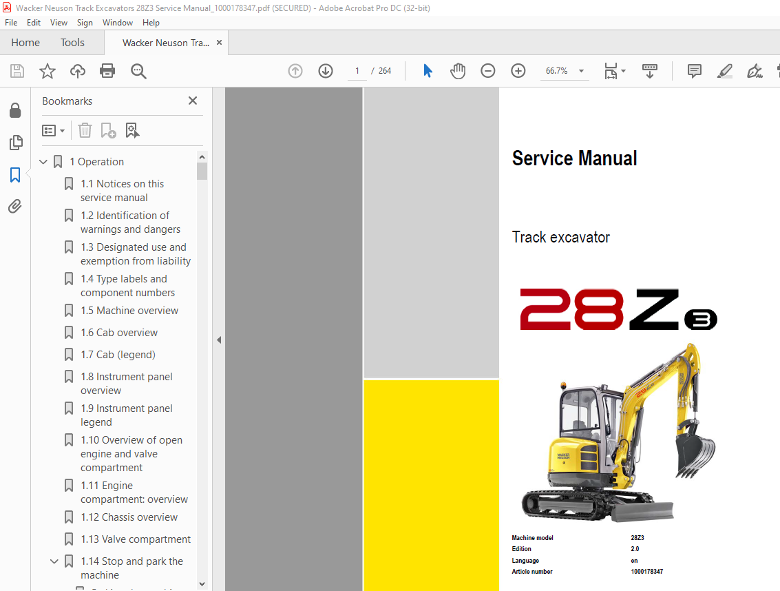
Wacker Neuson Track Excavators 28Z3 Service Manual_1000178347 – PDF DOWNLOAD
Language : English
Pages :264
Downloadable : Yes
File Type : PDF
TABLE OF CONTENTS:
Wacker Neuson Track Excavators 28Z3 Service Manual_1000178347 – PDF DOWNLOAD
1 Operation 12
11 Notices on this service manual 12
12 Identification of warnings and dangers 13
13 Designated use and exemption from liability 14
14 Type labels and component numbers 15
15 Machine overview 18
16 Cab overview 19
17 Cab (legend) 20
18 Instrument panel overview 21
19 Instrument panel legend 22
110 Overview of open engine and valve compartment 22
111 Engine compartment: overview 23
112 Chassis overview 24
113 Valve compartment 25
114 Stop and park the machine 26
Parking the machine on slopes 26
2 Specifications 28
21 Chassis 28
22 Engine 28
Fuel injection pump 28
Engine capacities 29
Engine tightening torques 29
23 Hydraulic system 29
Work hydraulics 29
Auxiliary hydraulics oil flow 28Z3 30
24 Undercarriage and swivel unit 30
25 Stabiliser blade 30
26 Electrical system 30
27 Noise levels 31
28 Vibration 31
29 Coolant compound table 31
210 Powertilt 31
211 Model-specific tightening torques 32
212 General tightening torques 32
Tightening torques for hydraulic screw connections (dry assembly) 32
Tightening torques for high-resistance screw connections 34
213 Dimensions model 28Z3 36
214 Dimensions model 28Z3 VDS 37
215 Lift capacity table 28Z3 (short stick) 39
216 Lift capacity table 28Z3 long stick (option) 40
217 Lift capacity table 28Z3 short stick and extra weight (option) 41
218 Lift capacity table 28Z3 long stick (option) and extra weight (option) 42
219 Lift capacity table 28Z3 VDS (short stick) 43
220 Lift capacity table 28Z3 long stick VDS (option) 44
221 Kinematics 45
3 Maintenance 48
31 Fluids and lubricants 48
Oil grades for the diesel engine, depending on temperature 49
Additional oil change and filter replacement (hydraulic system) 49
Oil grades for the hydraulic system, depending on temperature 50
32 Maintenance label 51
Explanation of symbols on the maintenance label 51
33 Maintenance plan (overview) 53
34 Service package 57
35 Introduction 57
36 Safety-relevant parts 57
37 Fuel system 58
Refuelling 59
Emptying the fuel tank 59
Stationary fuel pumps 60
Diesel fuel specification 60
Bleeding the fuel system 60
Water separator 61
Replacing the fuel filter 62
Tank for washer system 62
38 Engine lubrication system 63
Checking the oil level 63
Filling up engine oil 64
Changing engine oil 65
Replacing the engine oil filter cartridge 66
39 Engine and hydraulics cooling system 67
Specific safety instructions 67
Checking/filling up coolant 68
Checking the coolant level 68
Filling up coolant 69
Draining coolant 69
310 Air filter 70
Replacing air filter elements 70
Air intake 72
311 Change cab air filter 73
312 V-belt 74
Checking V-belt tension 74
Retightening the V-belt 75
313 Pressure check 77
General 77
Overview of measuring ports (up to serial number AG02712) 77
Overview of measuring ports (from serial number AG02713) 77
Checking pilot control pressure 78
Pressure check of variable displacement pump P1 79
Pressure check of variable displacement pump P2 80
Pressure check of gear pump P3 81
Secondary pressure limiting valve of the gear motor 82
Primary pressure limiting valves 82
314 Test report 83
315 Hydraulic system 87
Specific safety instructions 87
Checking the hydraulic oil level 88
Filling up hydraulic oil 89
Changing hydraulic oil 90
Monitoring the hydraulic oil return filter 90
Replacing the hydraulic oil filter 91
Draining condensation water from the hydraulic oil tank 91
Important information for the use of biodegradable oil 92
Checking hydraulic pressure lines 93
316 Pilot valve 94
317 Travelling drive 95
Checking the oil level and filling up oil 95
Draining oil 95
318 Tracks 96
Checking track tension 96
Adjusting track tension 97
319 Maintenance of attachments 98
320 Lubrication points 98
Parking the machine 98
321 Overview of lubrication points 99
Lubrication points on the stabiliser blade and stabiliser blade ram100
Lubrication points on the swivelling console and slewing ram100
Lubrication points on the boom, bucket and stick rams101
Lubrication points on the boom and stick102
Lubrication point on the joint rod102
Lubrication point on ball bearing race of live ring103
Lubrication point of live ring teeth103
Lubrication point of VDS live ring teeth104
VDS lubrication points (option)105
Powertilt lubrication points (option)105
Lubrication points of hydraulic quickhitch (option)106
Lubrication points of mechanical quickhitch (option)106
322 Cab106
323 Electrical system107
Service and maintenance work at regular intervals107
Instructions concerning specific components107
Alternator107
Battery108
324 General maintenance work109
Cleaning109
General instructions for all areas of the machine109
Inside the cab109
Cleaning the seat belt109
Exterior of the machine110
Engine compartment110
Shatter protection110
Screw connections and attachments110
Pivots and hinges110
325 Preparatory work before taking out of service111
326 Maintenance if the machine is out of service for a longer period of time111
Putting into operation again111
327 Fire extinguisher112
4 Engine114
41 3TNV76-NNS engine overview114
42 Fuel system116
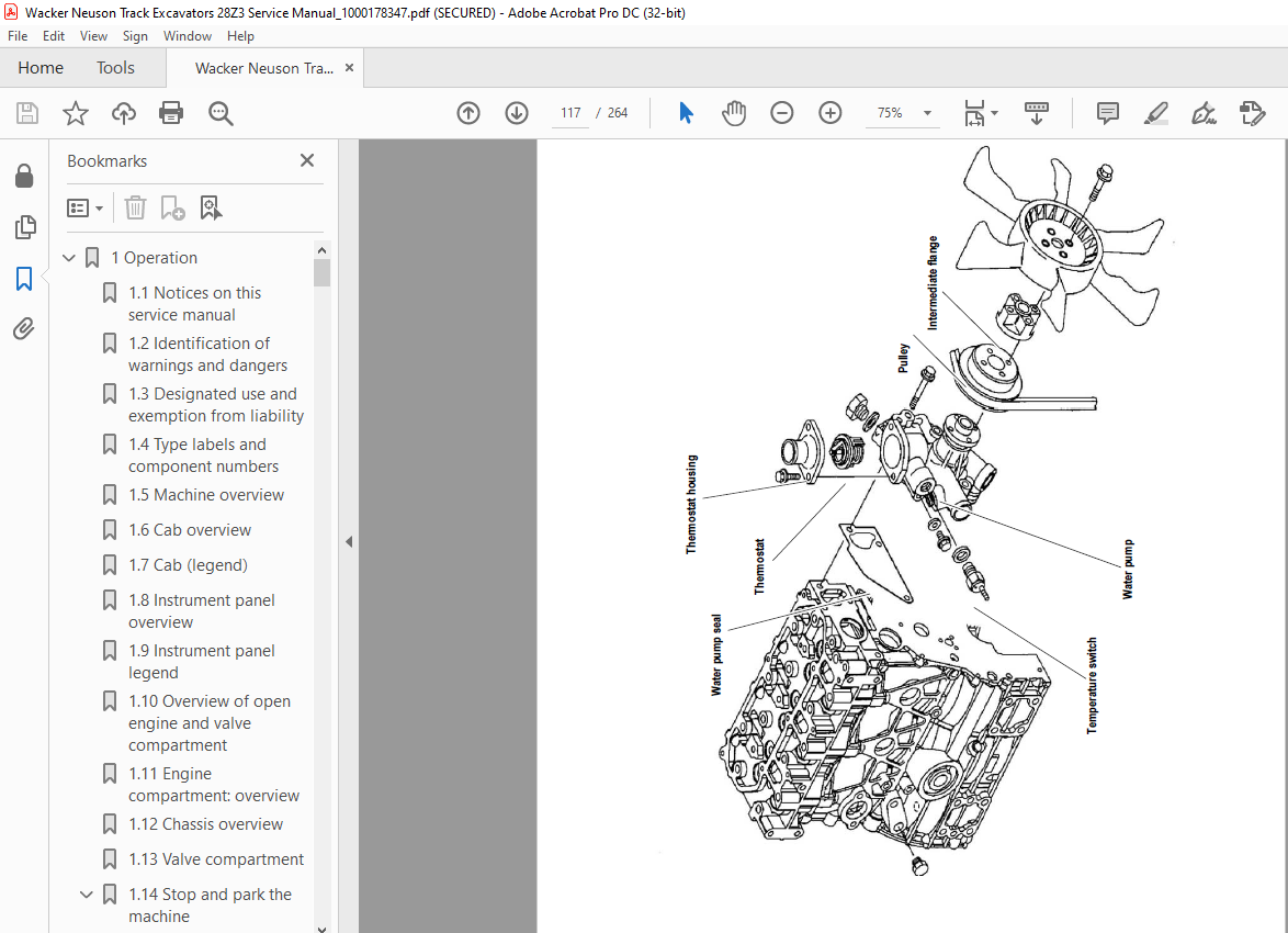
43 Cooling system117
44 Checking and adjusting valve clearance118
Lapping the intake and exhaust valves119
45 Tightening order for cylinder head bolts119
Order for removing the cylinder-head bolts:119
Order for mounting the cylinder-head bolts:119
46 Checking the injection nozzles120
Pressure check120
47 Checking the nozzle jet121
48 Injection time121
Checking injection time121
Setting injection time123
49 Removing and installing the injection pump124
Removing the injection pump124
Fitting the injection pump125
410 Measuring and adjusting the engine speed126
411 Compression126
412 Checking the coolant thermostat127
413 Checking the thermal switch127
414 Oil pressure switch128
415 Checking the coolant circuit128
416 Cleaning the cooling water channels128
417 Coolant and fuel hoses128
418 Crankcase vent129
419 Replacing the glow plugs129
420 Engine trouble130
5 Hydraulic system134
51 Hydraulic pump PVD-0B-23BP-8G3-5083A134
Pump unit: exploded view136
Pilot oil supply unit137
Dismantling the hydraulic pump138
Assembling the hydraulic pump140
Troubleshooting on the hydraulic pump144
52 Main valve block145
Ports145
Main control lines (legend)146
Pump/tank lines146
Main valve block diagram147
Pressure limiting valves148
Pump assignment149
53 Drive counterbalancing system150
Pump assignment for drive counterbalancing150
54 Regeneration – stick section151
55 Bucket pre-tension151
56 Auxiliary hydraulics flow rate adjustment152
57 Travelling drive153
Function154
58 Swivel unit156
Swivel unit brake157
59 Swivel joint159
Replace the sealing rings159
510 Swivel joint VDS (option)160
511 Pilot valves161
Joystick161
Pilot valve (driving)162
512 Changeover valve for SAE/ISO controls (option)164
513 Proportional valve (option)164
514 Changeover valve VDS (option)165
515 3/2 directional valve (option)165
516 Easy Lock valve (option)165
517 Hydraulic oil tank service valve (option)166
518 Breather filter166
519 Auxiliary hydraulics connections167
520 Troubleshooting in the hydraulic system168
521 Hydraulics diagram (legend) 0
522 Hydraulics diagram 28Z3 0
523 Hydraulics diagram for options 28Z3 0
524 Main valve block diagram 28Z3 0
6 Electrical system176
61 Ohm’s Law (current, voltage, resistance); power176
62 Measuring equipment, measuring methods176
63 Cable colour coding177
64 Relays177
Use, mode of function177
65 Socket178
66 Electric units178
67 Fuse box178
68 Alternator179
69 Starter179
610 Switches: overview180
Switch legend180
611 Cigarette lighter181
612 Radio and mounting/wiring for radio installation (option)181
613 Front working light182
614 Cab lights (option)182
615 Rotating beacon (option)183
616 Driving signal (option)183
617 Wiring diagram (legend) 0
618 Wiring diagram 0
619 Engine/chassis wiring harness (legend)190
620 Chassis/engine wiring harness192
621 Cab wiring harness193
622 Proportional controls wiring harness (option)194
623 Engine speed control wiring harness (option)195
624 Driving signal wiring harness (option)196
625 Hydraulic quickhitch wiring harness (option)197
626 Battery lead198
7 Options202
71 Counterweight202
Specifications202
72 Long stick202
Specifications202
73 Automatic engine speed setting203
Installation204
74 Grab pipework205
Attachments205
75 3rd control circuit/PowerTilt ports206
76 Safe load indicator207
77 Safe load indicator DE (from serial no AG04828) (safety valves for boom)208
Safe load indicator DE (serial nos AG02444 to AG04827) (safety valves for boom)209
Safe load indicator DE (up to serial no AG02443)210
Function210
Wiring diagram211
Setting the pressure switch211
78 Safe load indicator FR (from serial no AG04828) (safety valves for boom, stick and stabiliser blade)212
Safe load indicator FR (serial nos AG02444 to AG04827) (safety valves for boom, stick and stabiliser blade)213
Safe load indicator FR (up to serial no AG02443)214
Function214
Diagram (from serial no AG04828)215
Diagram (serial nos AG02444 to AG04827)216
Diagram (up to serial no AG02443)216
Setting the pressure switch217
79 Hose burst valve safety feature218
710 Mechanical quickhitch219
711 Hydraulic quickhitch (Easy Lock)220
712 3rd control circuit220
Function220
Diagram220
713 Drive interlock (antitheft protection)221
Position221
Disabling the drive interlock221
Enabling the drive interlock221
Programming221
714 Proportional controls223
Function223
Ports224
Measures to be taken in case of malfunctions224
Left-hand control lever224
Boom swivel controls225
Auxiliary hydraulics225
Hammer operation225
Adjusting control response226
Characteristic curves – status indicator226
Wiring harness227
Control unit connector assignment227
Measures to be taken in case of malfunctions228
Diagnosis display228
715 Engine oil service valve229
Function229
8 PowerTilt PTS06232
81 General instructions232
General safety instructions232
Checking the product233
Internal decompression valve233
Testing the hydraulic system of the machine233
Specifications/requirements234
82 Tools235
Making a tool VI for removing the seals236
83 Separating the bucket or equipment from the PowerTilt swivel device236
84 Separating the PowerTilt swivel device from the machine236
85 Exploded views PTS06237
PTS06 components237
Sealing kit A and bearing kit B PTS06 (overview)238
86 Assembly drawing239
87 Removing the standard journal coupling240
88 Removing the end cap, securing ring and internal decompression valve242
89 Removing the shaft243
810 Removing the piston tube body244
811 Removing the seals (kit A), shaft bearings and pressure discs (kit B)245
812 Checking components and dead centre marks246
813 Trial assembly247
814 Installing the seals (kit A), shaft bearings and pressure discs (kit B)247
Installing the end-cap seals and bearings248
Installing the piston seals and bearings249
Fitting the shaft seal and the bearing250
815 Installing the piston tube251
816 Installing the shaft252
817 Installing the end cap and the securing ring253
818 Installing the internal decompression valve254
819 Installing the standard journal coupling254
820 Lubrication and tests257
Lubrication257
Test for internal leaks257
Testing the internal decompression valve258
821 Securing the PowerTilt swivel device on the machine259
822 Fitting a bucket or equipment onto the PowerTilt swivel device259
823 Troubleshooting260
824 Adjusting the play on the PowerTilt261
Checking the circumferential play261
IMAGES PREVIEW OF THE MANUAL:
More products