$38
Wacker Neuson Track Excavators 50Z3 Service Manual_1000129833 – PDF DOWNLOAD
Wacker Neuson Track Excavators 50Z3 Service Manual_1000129833 – PDF DOWNLOAD
FILE DETAILS:
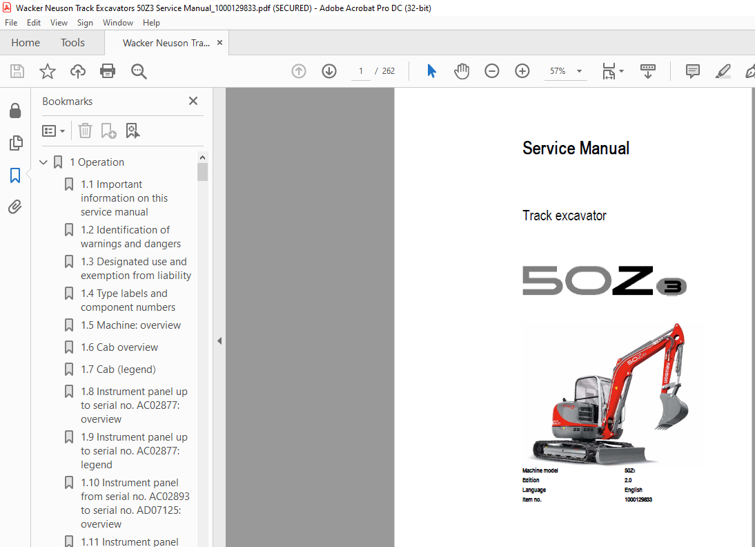
Wacker Neuson Track Excavators 50Z3 Service Manual_1000129833 – PDF DOWNLOAD
Language : English
Pages :262
Downloadable : Yes
File Type : PDF
TABLE OF CONTENTS:
Wacker Neuson Track Excavators 50Z3 Service Manual_1000129833 – PDF DOWNLOAD
1 Operation 11
11 Important information on this service manual 11
12 Identification of warnings and dangers 12
13 Designated use and exemption from liability 13
14 Type labels and component numbers 14
15 Machine: overview 16
16 Cab overview 17
17 Cab (legend) 18
18 Instrument panel up to serial no AC02877: overview 19
19 Instrument panel up to serial no AC02877: legend 20
110 Instrument panel from serial no AC02893 to serial no AD07125: overview 0
111 Instrument panel from serial no AC02893 to serial no AD07125: legend 0
112 Control elements 50Z3 (from serial no AH00579) 0
113 Engine compartment up to serial no AD07125: overview 25
114 Engine compartment (from serial no AH00579): overview 26
115 Chassis overview 27
116 Tilting the cab 28
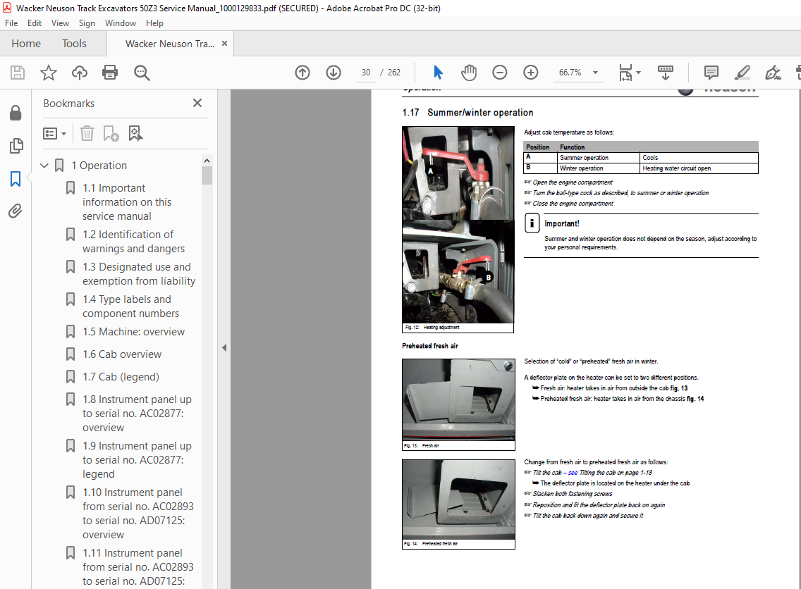
117 Summer/winter operation 30
Preheated fresh air 30
118 Turning the auxiliary hydraulics/boom swivel pedal around 31
2 Specifications 35
21 Chassis 35
22 Engine 35
Fuel injection pump 36
Engine capacities 36
Engine tightening torques 36
23 Hydraulic system 37
Auxiliary hydraulics oil flow 37
Screwable hose burst valve 38
24 Undercarriage and swivel unit 38
25 Stabiliser blade 38
26 Electric system 38
Fuse box in instrument panel 39
Main fuse box with relays underneath the cab 39
Relays 39
27 Noise levels 40
28 Vibration 40
29 Coolant compound table 40
210 Model-specific tightening torques 41
211 General tightening torques 41
Tightening torques for hydraulic screw connections (dry assembly) 41
Tightening torques for high-resistance screw connections 43
212 Dimensions model 50Z3 44
213 Lift capacity table 50Z3 45
214 Lift capacity table 50Z3 with long stick 46
215 Lift capacity table 50Z3 with counterweight 47
216 Lift capacity table 50Z3 with long stick and counterweight 48
217 Kinematics 49
218 Attachments 50
3 Maintenance 55
31 Fluids and lubricants 55
Additional oil change and filter replacement (hydraulics) 56
32 Maintenance label 57
Explanation of symbols on the maintenance label 57
33 Maintenance plan (overview) 59
34 Service package 62
Up to serial no: AD07125 62
From serial no: AH00579 62
35 Introduction 62
36 Fuel system 63
Specific safety instructions 63
Refuelling 63
Stationary fuel pumps 64
Diesel fuel specification 64
Bleeding the fuel system 64
Emptying the fuel tank 65
Fuel prefilter with water separator 65
Replacing the fuel filter 66
37 Engine lubrication system 67
Checking the oil level 67
Filling up engine oil 68
Changing engine oil 69
Replacing the engine oil filter cartridge 70
38 Cooling system 71
Specific safety instructions 71
Checking/filling up coolant 72
Draining coolant 73
39 Air filter 74
Replacing the filter 75
Functional check once a week of the dust valve 76
310 V-belt 77
Checking V-belt tension 77
Retightening the V-belt 78
Checking the V-belt of the air conditioning system 79
Tightening the V-belt of the air conditioning system 80
311 Pressure check 81
General 81
Checking pilot control pressure 81
Pressure check of variable displacement pump P1 82
Pressure check of variable displacement pump P2 83
Pressure check of gear pump P3 84
Secondary pressure limiting valve of the gear motor 84
Measuring ports: overview 85
Primary pressure limiting valves 85
312 Test report 86
313 Hydraulic system 89
Specific safety instructions 89
Checking the hydraulic oil level 90
Filling up hydraulic oil 91
Changing hydraulic oil 91
Monitoring the hydraulic oil reflux filter 92
Checking hydraulic pressure lines 93
314 Travelling drive 94
Checking the oil level and filling up oil 94
Draining oil 94
315 Chains 95
Checking chain tension 95
Setting the chains 96
316 Lubrication work 97
Stabiliser blade 97
Lubrication points on the swivelling console 97
Boom lubrication points 98
Lubrication points on the stick 98
Lubrication strip 99
Maintenance of attachments 99
317 Electric system100
Specific safety instructions100
Service and maintenance work at regular intervals100
Instructions concerning specific components101
Alternator101
Battery102
318 Cab103
Replacing the cab filter103
319 General maintenance work104
Cleaning104
General instructions for all areas of the machine104
Inside the cab105
Exterior of the machine105
Engine compartment105
Screw connections and attachments105
Pivots and hinges105
4 Engine109
41 Engine 4TNV88-PNS (up to serial no AD07125): overview109
42 Fuel system111
43 Checking and adjusting valve clearance112
44 Tightening order for cylinder head bolts113
45 Checking the injection nozzles114
Pressure check114
46 Checking the nozzle jet114
47 Injection time115
Checking injection time115
Setting injection time115
Replacement of fuel injection pump116
48 Adjusting engine revs117
49 Compression117
410 Checking the coolant thermostat117
411 Checking the thermal switch118
412 Oil pressure switch118
413 Checking the coolant circuit119
414 Engine 4TNV88-PNS (from serial no AH00579): overview120
415 Fuel system122
416 Removing the valve cover123
417 Checking and adjusting valve clearance123
418 Tightening order for cylinder head bolts124
419 Checking the injection nozzles125
Pressure check125
420 Checking the nozzle jet125
421 Injection time126
Checking injection time126
Setting injection time127
Replacement of fuel injection pump128
422 Adjusting engine revs129
423 Compression129
424 Checking the coolant thermostat129
425 Checking the thermal switch130
426 Oil pressure switch130
427 Checking the coolant circuit131
428 Engine trouble131
SHB_50z3_EN_1000129833_Teil2pdf 0
5 Hydraulic system135
51 Hydraulic pump PVD-2B-44BP-16G5-4713F (up to AD07125) PVD-2B-41BP-16G5-4713F (from AH00579)135
Pump unit: exploded view137
Pilot oil supply unit139
52 Main valve block140
Ports140
Legend141
Main valve block diagram142
Pressure limiting valves143
Pump assignment144
53 Drive counterbalancing system145
Pump assignment for drive counterbalancing145
Drive counterbalancing system with boom and right-hand side drive activation146
54 Regeneration – stick section147
55 Bucket pre-tension147
56 Flow rate adjustment of auxiliary hydraulics148
57 Pilot valves149
Joystick149
Pilot valve (driving)151
Pilot valve for auxiliary hydraulics153
Pilot valve for stabiliser blade154
58 Valves155
7/2 directional valve (changeover valve)155
4/3 directional valve156
Shuttle valve block157
Changeover valve for SAE/ISO controls (option)158
59 Travelling drive159
Function160
2nd speed range function160
510 Swivel unit163
Parking brake/multidisc brake function164
511 Swivel joint169
512 Breather filter170
513 Troubleshooting in the hydraulic system171
514 Hydraulics diagram A4172
515 Hydraulics diagram (legend)173
516 Hydraulics diagram 50Z3 A3 0
517 Options diagram 1 0
518 Options diagram 2 0
519 Main valve block diagram 50Z3 A3 0
6 Electric system181
61 Ohm’s Law (current, voltage, resistance); power181
62 Measuring equipment, measuring methods181
63 Cable colour coding183
64 Relays183
Use, mode of function183
65 Electric units184
66 Fuse box in instrument panel184
67 Main fuse box with relays184
68 Relays185
69 Socket185
610 Joystick tip switches186
Joystick (left)186
Joystick (right)186
611 Instrument panel overview187
612 Switch overview (up to serial no AD07125)188
613 Switch overview (from serial no AH00579)188
614 Alternator189
615 Starter189
616 Wiring diagram A4 legend up to serial no AC02889191
617 Wiring diagram A4 up to serial no AC02889192
618 Wiring diagram A4 legend from serial no AC02890193
619 Wiring diagram A4 from serial no AC02890194
620 Engine – chassis wiring harness A4 (legend)195
621 Engine – chassis wiring harness A4196
622 Wiring harness 1000109630 switches A4 up to serial no AC02889: legend197
623 Wiring harness 1000109630 switches A4 up to serial no AC02889198
624 Wiring harness switches A4 from serial no AC02890 (legend)199
625 Wiring harness switches A4 from serial no AC02890200
626 Cab roof wiring harness201
627 Armrest wiring harness202
628 Boom working light wiring harness203
629 Wiring diagram A3 up to serial no AC02889 (legend) 0
630 Wiring diagram A3 up to serial no AC02889 0
631 Wiring diagram A3 legend from serial no AC02890 0
632 Wiring diagram A3 from serial no AC02890 0
633 Engine – chassis wiring harness A3 (legend) 0
634 Engine – chassis wiring harness A3 0
635 Wiring harness 1000109630 switches A3 up to serial no AC02889 (legend) 0
636 Wiring harness 1000109630 switches A3 up to serial no AC02889 0
637 Wiring harness switches A3 from serial no AC02890 (legend) 0
638 Wiring harness switches A3 from serial no AC02890 0
639 Cab roof wiring harness A3 0
640 Armrest wiring harness A3 0
641 Boom working light wiring harness A3 0
7 Options221
71 Air conditioning221
Specific safety instructions221
Specifications221
Installation overview222
Components223
Filling up the air conditioning system225
Maintenance226
Troubleshooting227
72 Air-suspension seat229
Ports229
73 Counterweight229
Specifications229
74 Long stick229
Specifications229
75 Control circuit (pipework) connections for grab230
76 3rd control circuit connections230
77 Auxiliary hydraulics connections231
Quickhitch couplings231
Attachments232
78 Fuel-filling pump233
Ports234
79 Central lubrication system235
Position235
Ports235
Function236
Adjusting breaks and lubrication times237
Repair in case of clogging237
710 Service valve239
Function239
711 Safe load indicator D (safety valve for boom)240
Position240
Function241
Wiring diagram241
712 Safe load indicator F (safety valves for boom and stick)242
Position242
Function243
Wiring diagram244
713 3rd control circuit245
Function245
Diagram245
714 Electric auxiliary hydraulics246
Function246
715 Auxiliary hydraulics shock cartridge247
716 3rd control circuit shock cartridge248
717 Drive interlock (antitheft protection)249
Position249
Disabling the drive interlock249
Enabling the drive interlock249
Programming249
718 Quickhitch251
719 Automatic idling speed feature252
Function252
Diagram252
Wiring harness253
720 Proportional controls254
Function254
Ports254
Overview255
Wiring harness256
Control unit256
Control valve plug assignment257
Safety features258
Measures to be taken in case of malfunctions258
Diagnosis display258
721 Automatic revs setting (Tier 3A from AH00579)260
Function260
Installation261
IMAGES PREVIEW OF THE MANUAL:
More products