$38
Wacker Neuson Wheel Loaders 750, 850 Service Manual_1000183988 – PDF DOWNLOAD
Wacker Neuson Wheel Loaders 750, 850 Service Manual_1000183988 – PDF DOWNLOAD
FILE DETAILS:
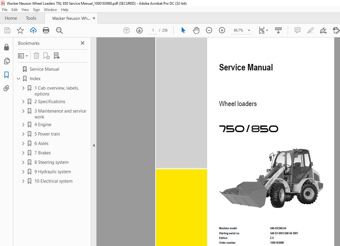
Wacker Neuson Wheel Loaders 750, 850 Service Manual_1000183988 – PDF DOWNLOAD
Language : English
Pages :256
Downloadable : Yes
File Type : PDF
TABLE OF CONTENTS:
Wacker Neuson Wheel Loaders 750 850 Service Manual_1000183988 – PDF DOWNLOAD
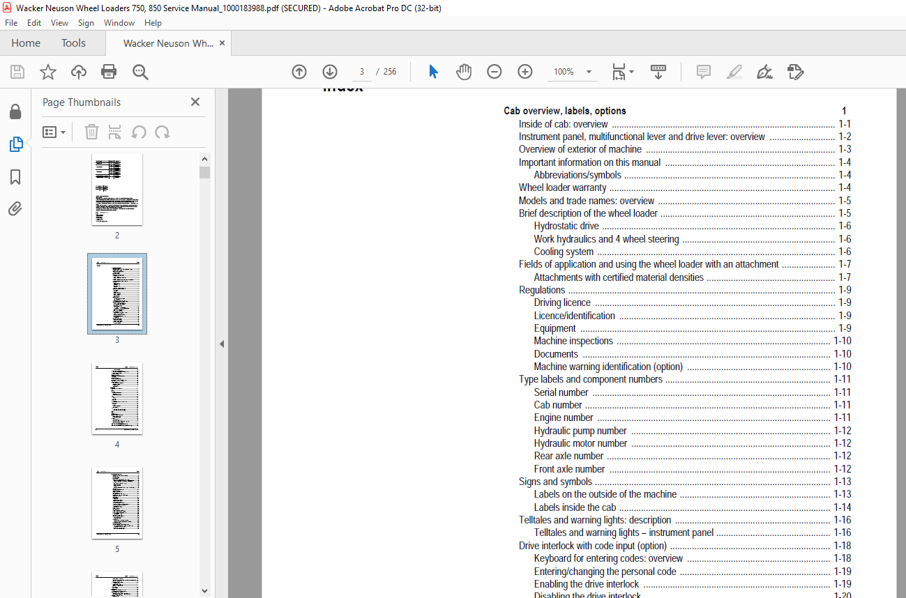
Cab overview, labels, options 1
Inside of cab: overview 1-1
Instrument panel, multifunctional lever and drive lever: overview 1-2
Overview of exterior of machine 1-3
Important information on this manual 1-4
Abbreviations/symbols 1-4
Wheel loader warranty 1-4
Models and trade names: overview 1-5
Brief description of the wheel loader 1-5
Hydrostatic drive 1-6
Work hydraulics and 4 wheel steering 1-6
Cooling system 1-6
Fields of application and using the wheel loader with an attachment 1-7
Attachments with certified material densities 1-7
Regulations 1-9
Driving licence 1-9
Licence/identification 1-9
Equipment 1-9
Machine inspections 1-10
Documents 1-10
Machine warning identification (option) 1-10
Type labels and component numbers 1-11
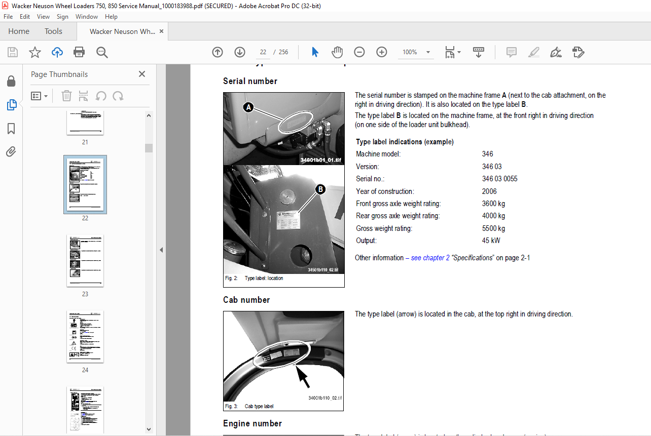
Serial number 1-11
Cab number 1-11
Engine number 1-11
Hydraulic pump number 1-12
Hydraulic motor number 1-12
Rear axle number 1-12
Front axle number 1-12
Signs and symbols 1-13
Labels on the outside of the machine 1-13
Labels inside the cab 1-14
Telltales and warning lights: description 1-16
Telltales and warning lights – instrument panel 1-16
Drive interlock with code input (option) 1-18
Keyboard for entering codes: overview 1-18
Entering/changing the personal code 1-19
Enabling the drive interlock 1-19
Disabling the drive interlock 1-20
Taking the drive interlock out of service 1-21
Putting the drive interlock back into service again 1-21
Interruption of drive interlock power 1-21
Drive interlock maintenance 1-21
Key-based drive interlock (option) 1-22
Key-based drive interlock: scope of delivery 1-22
Coding (“training”) new ignition keys 1-22
Enabling (locking) the drive interlock 1-23
Disabling (releasing) the drive interlock 1-23
Deleting coded keys 1-23
Safety functions 1-23
Battery master switch (option) 1-24
Interrupting power supply 1-24
Switching on power supply: 1-24
Oil and fuel preheater (option) 1-24
Oil preheater operation 1-24
Index
I-2 Serv-HB 34603_04 EN – Ausgabe 20 * 34603_04s20_enIVZfm
Index
Fuel preheater operation 1-24
Jump-starting the engine (external battery) 1-25
Safety instructions regarding external starting aids 1-25
Providing external starting aid 1-25
Manual throttle (option) 1-26
Low-speed control (option) 1-26
Electric connection – front socket (option) 1-27
Working lights 1-27
Rotating beacon (option) 1-27
Backup warning system (option) 1-28
Additional control circuit for attachments (option) 1-28
“Hose burst valve” safety feature (option) 1-29
Towing the machine 1-30
Safety instructions for towing away 1-30
Getting ready for towing 1-30
Towing the machine 1-31
Once towing is over 1-31
Specifications 2
Models and trade names: overview 2-1
Frame 2-1
Engine 2-1
Power train 2-2
Variable displacement pump 2-2
Boost pump 2-2
Variable displacement motor 2-2
Axles 2-3
Brakes 2-3
Service brake 2-3
Parking brake 2-3
Steering system 2-4
Work hydraulics 2-4
Hydraulic pump, control valve, lift and tilt rams 2-4
Electrical system 2-5
Electric units 2-5
Fuse box 2-5
Main fuse box with relays 2-6
Switching relays 2-6
Tyres 2-7
Tyres for wheel loader model 346-03 (750) 2-7
Tyres for wheel loader model 346-04 (850) 2-7
Weights 2-7
Noise levels 2-8
Vibration 2-8
Coolant compound table 2-8
Tightening torques, conversion tables 2-9
General tightening torques 2-9
Specific tightening torques 2-9
Payloads 2-10
Loader unit with bucket 2-10
Loader unit with pallet forks 2-10
Loader unit with pallet forks (foldable fork arms option) 2-11
Loader unit with load hook (option) 2-11
Wheel loader dimensions with bucket (model 346-03) 2-12
Wheel loader dimensions with bucket (model 346-04) 2-13
Wheel loader dimensions with pallet forks (models 346-03/346-04) 2-14
Serv-HB 34603_04 EN – Ausgabe 20 * 34603_04s20_enIVZfm I-3
Index
Maintenance and service work 3
Explanation of symbols on the maintenance label 3-1
Maintenance label 3-2
Fluids and lubricants 3-3
Maintenance plan 3-4
Important information on maintenance and service work 3-7
Service and maintenance work according to the maintenance plan 3-7
Service and maintenance work on the separate components 3-7
Fuel system 3-8
General safety instructions for refuelling 3-8
Diesel fuel specification 3-8
Stationary fuel pumps 3-8
Refuelling 3-9
Checking/cleaning the additional fuel filter (water separator, option) 3-9
Replacing the fuel filter 3-10
Cleaning the fuel pump screen filter 3-11
Bleeding the fuel system 3-12
Checking/filling up the engine oil 3-13
Changing engine oil 3-14
Replacing the engine oil filter cartridge 3-15
Cleaning the radiator fins of the oil/water radiator 3-16
Checking the coolant level 3-17
Draining coolant 3-18
Filling up coolant 3-19
Hydraulic system 3-20
Specific safety instructions 3-20
Checking hydraulic pressure lines 3-21
Specific safety instructions 3-21
Monitoring the hydraulic oil reflux filter 3-22
Important information for the use of biodegradable oil 3-22
Maintenance of the hydraulic oil reflux filter 3-23
Changing the filter insert 3-23
Checking the hydraulic oil level 3-24
Filling up hydraulic oil 3-24
Replacing hydraulic oil 3-25
Oil levels: rear axle transfer gearbox 3-26
Oil levels: front and rear axle differentials 3-27
Oil levels: front and rear axle planetary drives 3-28
Air filter maintenance 3-29
Checking the air filter for dirt 3-29
Replacing the air filter cartridge 3-30
Maintenance of the diesel engine V-belt 3-31
Checking V-belt tension 3-31
Retightening the V-belt 3-31
Lubrication work 3-32
Lubricating the rear axle oscillation-type bearing 3-32
Lubricating the front and rear axle planetary drive bearings 3-32
Lubricating the loader unit 3-33
Maintenance of attachments 3-33
Lubricating with the central lubrication system (option) 3-34
General functional description of the central lubrication system 3-34
Setting the lubrication and break times 3-35
Filling the central lubrication system 3-35
Central lubrication system diagram 3-36
I-4 Serv-HB 34603_04 EN – Ausgabe 20 * 34603_04s20_enIVZfm
Index
Mounting the high-pressure hoses 3-37
Instructions for troubleshooting in case of central lubrication system blocking 3-38
Repairing a blocked distributor 3-39
Troubleshooting table (overview) 3-40
Brake system maintenance 3-41
Specific safety instructions 3-41
Checking/filling up the brake fluid level 3-41
Repair work on the brake system 3-41
Tyre maintenance 3-42
Daily tyre checks 3-42
Changing wheels 3-43
Maintenance of cab heating and fresh air filter 3-44
Cleaning the dust filter of the heating system 3-44
Air conditioning (option): maintenance 3-45
General instructions regarding the air conditioning system 3-45
Daily functional and visual checks of the air conditioning 3-46
Maintenance of the electrical system 3-47
General instructions 3-47
Safety instructions regarding the electrical system and the battery 3-47
Battery maintenance 3-48
Service and maintenance work at regular intervals 3-49
Electric lines, bulbs, ignition lock, relays and fuses 3-49
Alternator 3-49
General maintenance work 3-50
Specific safety instructions 3-50
Cleaning with washing solvents 3-50
Cleaning with compressed air 3-50
Cleaning with a high-pressure cleaner or steam jet 3-50
Cleaning with volatile and flammable anticorrosion agents and sprays 3-50
Cleaning inside the cab 3-51
Cleaning the seat belt 3-51
Cleaning the exterior of the machine 3-51
Cleaning the engine compartment 3-52
Screw connections, hinges 3-52
Maintenance work “Aggressive Media” (option) 3-53
Anticorrosion protection applied in the factory 3-53
Components coated with anticorrosive wax 3-53
Measures for maintaining anticorrosive protection 3-54
Applying the protective anticorrosion coating 3-55
Treatment of oxidised surfaces 3-55
Engine 4
Engine designation 4-1
Fuel specification 4-1
Coolant specification 4-1
Electrical components (overview) 4-2
Diesel engine D 2011 L04 W overview 4-3
Engine oil cooling 4-4
Belt drive with cooling ports 4-5
Fuel system 4-6
Checking and adjusting valve clearance 4-7
Replacing the fuel injection pump 4-8
Switching off minus compensation 4-13
Heating connection 4-13
Removing/mounting the cylinder head 4-14
Sealing the bleed valve 4-17
Sealing the intake/exhaust manifold 4-17
Serv-HB 34603_04 EN – Ausgabe 20 * 34603_04s20_enIVZfm I-5
Index
Replacing the toothed belt and the tensioning pulley 4-18
General instructions 4-18
Removing the toothed belt and the tensioning pulley 4-18
Checking engine control times 4-25
Engine trouble 4-27
Notes: 4-29
Power train 5
Variable displacement pump test ports (20 kph) 5-1
Variable displacement pump 20 kph 5-2
Variable displacement pump test ports (30 kph) 5-3
Variable displacement pump 30 kph 5-4
Variable displacement motor (20/30 kph) 5-5
Inching valve overview 5-6
Inching valve circuit 5-7
Inching valve diagram 5-8
Drive circuit 5-9
Drive diagram 5-10
Towing and transporting the machine 5-11
Safety instructions 5-11
Getting ready for towing 5-11
Test report: 20 kph power train 5-12
Test report: 30 kph power train 5-13
Adjustment instructions 5-14
Tools required 5-14
Adjusting boost pressure 5-14
Adjusting starting engine speed/control pressure 5-15
Setting high pressure/drive pressure 5-16
Setting the secondary valves for forwards/reverse driving 5-17
Checking/setting the hydraulic resistance (characterisic curve) of the pump 5-17
Check engine droop 5-18
Setting control initiation on the variable displacement motor 5-18
Setting the wheel speed 5-19
Axles 6
Axle overview 6-1
Front axle screw connections 6-2
Sealing work (joint housing/axle carrier) 6-3
Sealing the rear axle in case of oil migration (axle/gearbox) 6-14
Assembly 6-17
Setting the gear drive 6-20
Removing the gearbox 6-24
Input shaft version 1 sealing: overview 6-30
Assembling the gearbox 6-31
Brakes 7
Brake circuit 7-1
Brake diagram 7-2
Service brake/inching valve function 7-2
Parking brake circuit 7-3
20 kph inching valve circuit 7-4
Service brake 7-5
Important information on the brake system 7-5
Brake calliper maintenance 7-5
Bleeding the brake system with bleed equipment 7-6
Notes: 7-7
I-6 Serv-HB 34603_04 EN – Ausgabe 20 * 34603_04s20_enIVZfm
Index
Steering system 8
Steering circuit 8-1
Steering circuit 8-2
Steering system adjustment 8-3
Function 8-3
Hydraulic ports on servostat 8-3
Pressure relief valve: adjustment 8-3
Sealing steering rams 8-4
Checking a steering ram 8-5
Overview of steering ram setting 8-5
Necessary tools 8-5
How to check and set the steering rams 8-6
Checking the track setting (1) 8-7
Correcting the track setting (2) 8-7
Setting the steering limit (3) 8-8
Checking steering synchronisation (4) 8-9
Checking the bypass 8-9
Bleeding the steering rams 8-10
Setting steering synchronisation (5) 8-11
Final check/test run 8-11
Hydraulic system 9
Work hydraulics test report 9-1
Work hydraulics oil supply 9-2
Control valve ports 9-3
Priority valve ports 9-3
Priority valve diagram 9-4
Load stabiliser ports 9-4
Load stabiliser circuit 9-5
Load stabiliser diagram 9-5
Lift ram: sealing work 9-6
Tilt ram: sealing work 9-7
Control ram (quickhitch frame): sealing work 9-8
Notes: 9-9
Work hydraulics diagram 9-10
Hose burst valve hydraulics diagram (option) 9-11
Serv-HB 34603_04 EN – Ausgabe 20 * 34603_04s20_enIVZfm I-7
Index
Electrical system 10
Ohm’s Law (current, voltage, resistance); power 10-1
Measuring equipment, measuring methods 10-1
Terminal description 10-2
Colour coding of electric lines 10-6
Extract from DIN 72551, sheet 4 10-6
Other colour codes (identical to IEC 757) 10-8
Switching relay function 10-8
Use, mode of function 10-8
Terminal description on relay 10-8
Starter, battery, alternator 10-9
Fuse box 10-9
Main fuse box with relays 10-10
Switching relays 10-10
Description of blocking diodes 10-11
Blocking diodes V8, V9 10-11
Blocking diode V10 10-11
Blocking diode V11 10-11
Blocking diodes V16, V17 10-11
Blocking diodes V20, V21 10-11
Overview of switch assignment 10-12
Retrofitting a rotating beacon 10-13
Retrofitting the backup warning system 10-13
Retrofitting 2 front working lights 10-14
Retrofitting 2 front working lights and 1 rear working light 10-14
Retrofitting 2 front working lights and 2 rear working lights 10-15
Electric diagram legend 10-16
Electric diagram sheet 1 10-17
Electric diagram sheet 2 10-18
Notes: 10-19
IMAGES PREVIEW OF THE MANUAL:
More products