$26
XTREME Telehandler XR1255 Perkins 1204 Tier 4 Interim Operation & Safety Manual PDF
XTREME Telehandler XR1255 Perkins 1204 Tier 4 Interim Operation & Safety Manual – PDF DOWNLOAD
FILE DETAILS:
XTREME Telehandler XR1255 Perkins 1204 Tier 4 Interim Operation & Safety Manual – PDF DOWNLOAD
Language : English
Pages : 76
Downloadable : Yes
File Type : PDF
PN 24907-000-02
IMAGES PREVIEW OF THE MANUAL:
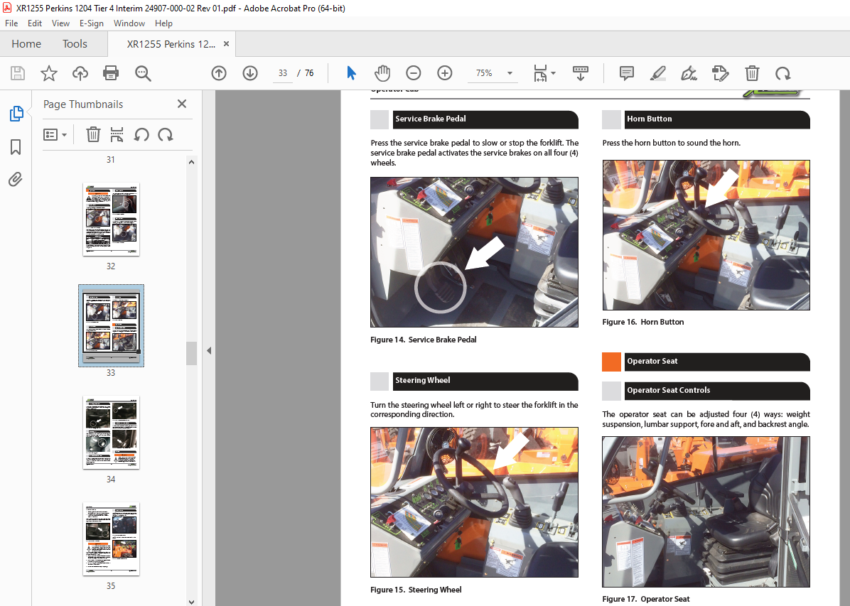
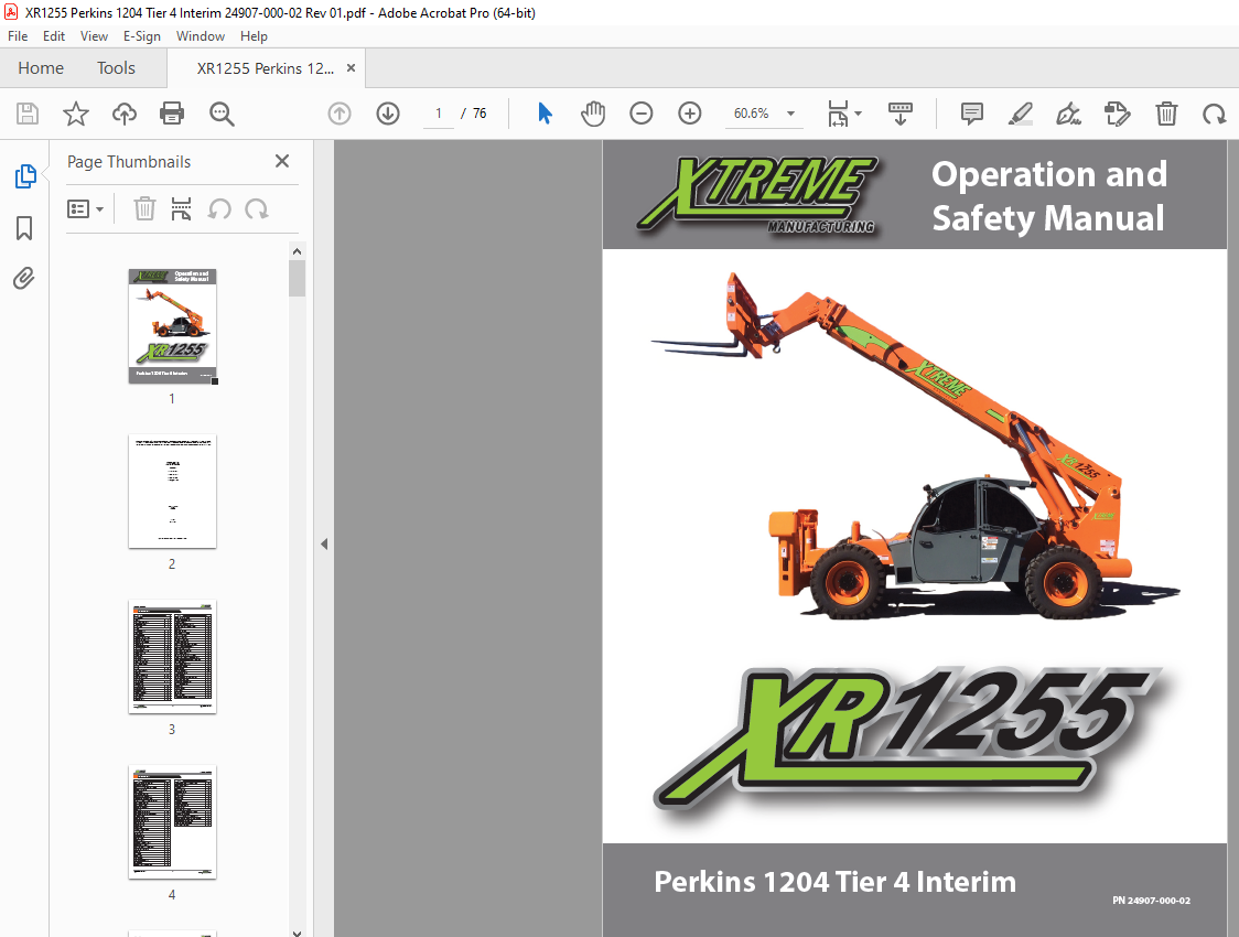
TABLE OF CONTENTS:
XTREME Telehandler XR1255 Perkins 1204 Tier 4 Interim Operation & Safety Manual – PDF DOWNLOAD
Introduction
General 5
Replacement Manuals 5
Model/Serial Plate 5
Orientation 5
Safety
Safety Disclaimer 6
Signal Words 6
Safety Symbols 6
Employer Responsibility 9
Operator Responsibility 9
Operator Qualifications 9
Modifications 9
Mounting/Dismounting 10
Work Site Safety 10
Before Starting Forklift 11
Operation Safety 12
Load Safety 14
Attachments 15
Shut Down Procedure 15
Forklift Maintenance 15
Dead Engine Towing 17
Labels
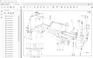
Labels 18
Replacement Labels 21
Features
Standard Equipment 30
Optional Equipment 30
Specifications
Specifications 31
Operator Cab
Ignition Switch 32
Accessory Outlet 32
Accelerator Pedal 32
Service Brake Pedal 33
Steering Wheel 33
Horn Button 33
Operator Seat 33
Table of Contents
Description Page
Operator Seat Controls 33
Weight Suspension Lever 34
Lumbar Support 34
Fore and Aft Adjustment Lever 34
Backrest Angle Adjustment Lever 34
Seat Belt 35
Rear View Mirrors 35
Controls and Indicators 36
Travel Select Lever 36
Gear Select Switch 36
Parking Brake Switch 37
Load Capacity Charts 37
Hydraulic Oil Temperature Indicator 37
Low Brake Pressure Indicator 37
Rear Axle Lock Indicator 37
Engine Warning Indicator 37
Engine Stop Indicator 38
Glow Plugs Wait to Start Indicator 38
Tier 4 Interim Digital Display (Optional) 38
Display Keypad Functions and Navigation 38
Basic Navigation 39
The Display at Power Up 39
Main Menu Options 39
Display Setup 40
Service Reminders 40
Language Selection 41
Units Selection 41
Backlight and Contrast Adjustment 41
Engine Speed Control 41
Access Stored Fault Codes 41
Clearing Fault Codes 41
Hour meter 42
Voltage Gauge 42
Fuel Gauge 42
Oil Gauge 42
Coolant Gauge 43
Turn Signal and Hazard Switches 43
Table of Contents
Operation Manual 4
Rear Axle Centering Indicator 43
Steering Select Switch 43
Declutch Indicator / Declutch Switch 44
Outrigger Switches 44
Boom Control 44
Attachment Tilt Switch 45
Frame Sway Control Handle 45
Auxiliary Attachment Control 46
Windshield Wiper and Washer Switch 46
Boom Angle Indicator 47
Boom Extend Letters 47
Frame Level Indicator 47
Operation
Pre-Operation Inspection 48
Pre-Operation Inspection Checklist 50
Functional Tests 51
Operator Maintenance 52
Before Starting Forklift 53
Starting Forklift 54
Normal Starting 54
Soft Starting 55
Excessive Engine Idling 55
Jump Starting 55
Forklift Travel 56
Steering Modes 56
Starting Travel 57
Stopping Travel 57
Changing Travel Direction 57
Shut Down Procedure 57
Warning Indicators and Gauges 57
Engine Indicator Chart 58
Refueling 59
Fuel Types 59
Pintle Hook 59
Attachments 59
Attachment Disclaimer 59
Fork Ratings 59
Standard Carriage Operation 60
Fork Positioning Carriage Operation 60
Quick Attach System 61
Load Handling 64
Boom Lift Point 65
Suspended Loads 65
Pick Up a Load 65
Carry a Load 66
Place a Load 66
Load Shift 66
Elevating Personnel 66
Load Capacity Charts 68
Frame Leveling 70
Preventive Maintenance
Establishing a Maintenance Program 71
Maintenance Schedule 71
Boom Emergency Lower Down Valve 73
Do Not Operate – Accident Prevention Tags 74
New or Additional Operators 74
Lockout/Tagout Procedure 74
“Do Not Operate” Tags 75
More products