$25
XTREME Telehandler XR2045 Operation & Safety Manual 24938-000-01 PDF
XTREME Telehandler XR2045 Operation & Safety Manual 24938-000-01 – PDF DOWNLOAD
FILE DETAILS:
XTREME Telehandler XR2045 Operation & Safety Manual 24938-000-01 – PDF DOWNLOAD
Language : English
Pages : 80
Downloadable : Yes
File Type : PDF
IMAGES PREVIEW OF THE MANUAL:
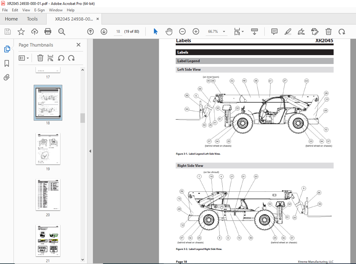
TABLE OF CONTENTS:
XTREME Telehandler XR2045 Operation & Safety Manual 24938-000-01 – PDF DOWNLOAD
Introduction 3
General 3
Replacement manuals 3
Model/Serial Number Plate 3
Orientation 3
Safety 4
Safety Disclaimer 4
Signal Words 4
Safety Symbols 4
Employer Responsibility 7
Operator Responsibility 7
Operator Qualifications 7
Modifications 7
Mounting/Dismounting 8
Work Site Safety 8
Before Starting Forklift 9
Operation Safety 10
Load Safety 13
Attachments 13
Shut Down Procedure 13
Forklift Maintenance 14
Dead Engine Towing 16
Parking Brake Release (Front Axle) 16
Re-activating Parking Brakes (Front Axle) 16
Labels 18
Label Legend 18
Left Side View 18
Right Side View 18
Front View 19
Rear View 19
Cab View 19
Replacement Labels 21
Features 30
Standard Equipment 30
Optional Equipment 30
Specifications 31
Operator Cab 32
Ignition Switch 32
Accessory Outlet 32
Accelerator Pedal 32
Service Brake Pedal 33
Steering Wheel 33
Horn Button 33
Operator Seat 33
Operator Seat Controls 33
Weight Suspension Lever 33
Lumbar Support 34
Fore and Aft Adjustment Lever 34
Backrest Angle Adjustment Lever 34
Seat Belt 34
Rear View Mirrors 35
Controls and Indicators 35
Travel Select Lever 35
Gear Select Switch 36
Parking Brake Switch 36
Load Capacity Charts 36
Hydraulic Oil Temperature Indicator 36
Low Brake Pressure Indicator 37
Rear Axle Lock Indicator 37
Hourmeter 37
Voltage Gauge 37
Fuel Gauge 38
Oil Gauge 38
Coolant Gauge 38
Light Switches 38
Work Light Switch 38
Rear Axle Centering Indicator 39
Steering Select Switch 39
Declutch Indicator 39
Declutch Switch 39
Tier 4 Interim Digital Display (Optional)
Activate Elevated Idle
Deactivate Elevated Idle
Summary of the Regeneration Process
Outrigger Toggle Switches
Boom Control
Attachment Tilt Switch Frame Sway Control Handle
Auxiliary Attachment Control
Optional Controls and Indicators
Two Wheel Rear (2WR) Steering Switch Boom Angle Indicator
Boom Extend Letters
Frame Level Indicator 51
Fuel Types 44
Tier 4 Interim Engines
Engine Warning Indicator
Engine Stop Indicator
Glow Plugs wait to Start Indicator
Starting Forklift
Starting
T4i Digital Display
Main Menu Options 41
Display Setup 43
Service Reminders 43
Engine Speed Contr o l 44
Access and Clearing Fault Codes 44
Operation 52
Pre-Operation Inspection
Pre-Operation Inspection Checklist
Functional Tests
Functional Test
Checklist
Operator Maintenance
Before Starting Forklift
Attachment Connection 66
Attachment Removal
Load Handling
Suspended Loads
Pick Up A Load
Carry A Load
Place A Load
Load Shift
Elevating Personnel
Frame Leveling
Load Capacity Charts 70
Using Load Capacity Charts
Reading Load Capacity Charts
Standard Carriage Load Capacity Chart 72
Preventive Maintenance 73
Establishing A Maintenance Program
Maintenance Schedules
Boom Emergency Lower Down Valve
Do Not Operate – Accident Prevention Tags
New or Additional Operators 75
Lockout / Tagout 76
Lockout/Tag out Procedure 76
Removing Forklift From Service 76
Returning Forklift To Service 76
“Do Not Operate” Tags 77
Steering Modes 61
Crab Steering Two Wheel Steering (2W) Four Wheel Steering (4W) Two Wheel Rear Steering (2WR) (Optional) 61
Maximum Fork Sweep
Starting Travel
Shifting Gears
Stopping Travel
Changing Travel Direction Shut Down Procedure
Warning Indicators and Gauges
Refueling
Attachments
Attachment Disclaimer
Fork Ratings
Standard Carriage Operation
Swing Carriage Operation
Quick Attach System
Starting Forklift 58
Normal Starting 58
Cold Starting 58
Soft Starting 58
Excessive Idling 58
Jump Starting 59
Forklift Travel 61
More products