$41.95
Yale (E876) (GDP 190DC, 210DC, 230DC, 230DCS, 250DC, 280DC) Service Manual PDF
Yale Forklift E876 (GDP190DC, GDP210DC, GDP230DC, GDP230DCS, GDP250DC, GDP280DC) Service Manual – PDF DOWNLOAD
FILE DETAILS:
Yale Forklift E876 (GDP190DC, GDP210DC, GDP230DC, GDP230DCS, GDP250DC, GDP280DC) Service Manual – PDF DOWNLOAD
Language : English
Pages : 1500
Downloadable : Yes
File Type : PDF
IMAGES PREVIEW OF THE MANUAL:
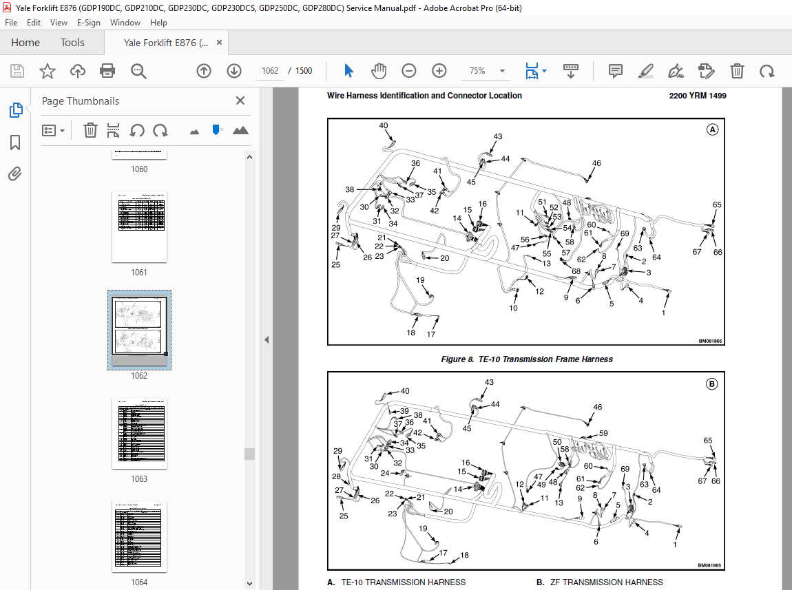
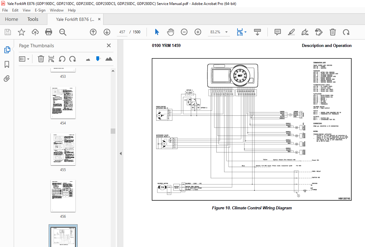
TABLE OF CONTENTS:
Yale Forklift E876 (GDP190DC, GDP210DC, GDP230DC, GDP230DCS, GDP250DC, GDP280DC) Service Manual – PDF DOWNLOAD
524150779 1400YRM0046 (08 2012) US EN 1
toc 1
Differential 1
Safety Precautions Maintenance and Repair 2
General 5
Description 5
Differential Repair 5
Remove 5
Differential Carrier From Axle Housing, Remove 5
Differential and Ring Gear From Differential Carrier, Remove 9
Drive Pinion and Pinion Carrier From Differential Carrier, Remov 11
Disassemble 12
Differential and Ring Gear Assembly, Disassemble 12
Drive Pinion and Pinion Carrier, Disassemble 13
Clean and Inspect 16
Assemble 17
Pinion, Bearings, and Pinion Carrier, Assemble 17
Pinion Bearings, Adjust Preload 17
Press Method 17
Yoke or Flange Method 18
Triple-Lip Seal, Install 19
Pinion Carrier Shim Set, Adjust Thickness (Depth of Pinion) 20
Differential and Ring Gear, Assemble 22
Differential Gears Rotating Torque, Check 24
Differential and Ring Gear Assembly, Install 25
Differential Bearings, Preload Adjust 26
Ring Gear, Runout Check 27
Ring Gear Backlash, Adjust 28
Gear Set, Tooth Contact Pattern Check 30
Thrust Screw, Install and Adjust 33
Install 33
Differential Assembly Into Axle Housing, Install 33
Specifications 34
Troubleshooting 38
tables 1
Table 1 Ring Gear Backlash Adjustment Specifications 29
Table 2 Ring and Pinion Tooth Contact Adjustment 30
Table 3 General Specifications 34
Table 4 Rivet Installation Pressure 34
Table 5 Pinion Adjustment 34
Table 6 Pinion Preload Pressure 35
Table 7 Torque Specifications 36
Table 8 Torque Specifications for Metric Hardware 37
Table 9 Torque Specifications for Metric (Fine) Hardware 37
524150780 1400YRM0944 (08 2012) US EN 41
toc 41
Planetary Drive Axle 41
Safety Precautions Maintenance and Repair 42
General 45
Description 45
Operation 47
Identification 47
Removal 48
Disassembly 48
Planetary Spider and Gearing Assembly GDP80-120DB (GP170-280DB) 49
Planetary Spider and Gearing Assembly GDP130-160EB (GP300-360EB) 50
Wheel End 52
Spindle and Piston Housing 53
Cleaning 54
Clean Ground or Polished Parts 54
Clean Parts With Rough Finish 54
Clean Axle Assemblies 54
Drying Cleaned Parts 54
Corrosion Prevention 54
Parts Inspection 55
Tapered Roller Bearings 55
Bevel Pinion and Ring Gear Sets 56
Main Differential Assembly 56
Axle Shafts 56
Yoke 56
Brakes 56
Repair or Replace Parts 56
Repair Welding 57
Apply Silicone Gasket Material 57
Assembly 57
Spindle and Piston Housing to Axle Housing 57
Wet Disc Brakes 58
Adjust Wheel Bearing Preload 59
Planetary Spider and Gearing Assembly GDP80-120DB (GP170-280DB) 60
Planetary Spider and Gearing Assembly GDP130-160EB (GP300-360EB) 60
Planetary Spider Assembly 61
Installation 62
Fill Wet Disc Brakes With Hydraulic Fluid 62
Torque Specifications 63
Lubrication Specification 64
524150781 1400YRM0945 (08 2011) US EN 67
toc 67
Planetary Drive Axle 67
Safety Precautions Maintenance and Repair 68
General 71
Description 71
Operation 73
Identification 73
Removal 74
Disassembly 75
Brake Drum 75
Planetary Spider and Gearing Assembly GDP/GLP80-120DB (GDP/GLP17 76
Dry Brakes 76
Planetary Spider and Gearing Assembly GDP/GLP130-160EB (GDP/GLP3 78
Spindle and Brake Spider 80
Cleaning 80
Ground or Polished Parts 80
Parts With Rough Finish 81
Axle Assemblies 81
Drying Cleaned Parts 81
Corrosion Prevention 81
Parts Inspection 81
Tapered Roller Bearings 81
Bevel Pinion and Ring Gear Sets 82
Main Differential Assembly 83
Axle Shafts 83
Yoke 83
Brakes 83
Repair or Replace Parts 83
Repair Welding 83
Apply Silicone Gasket Material 83
Assembly 84
Spindle, Brake Spider, and Brake 84
Wheel End 85
Adjust Wheel Bearing Preload 85
Planetary Spider and Gearing Assembly GDP/GLP80-120DB (GDP/GLP17 86
Planetary Spider and Gearing Assembly GDP/GLP130-160EB (GDP/GLP3 87
Planetary Spider Assembly 87
Installation 88
Torque Specifications 89
Lubrication Specification 90
524150797 8000YRM0231 (02 2023) US EN 93
General 99
Threaded Fasteners 99
Nomenclature, Threads 99
Strength Identification 100
Cotter (Split) Pins 101
Fastener Torque Tables 106
Conversion Table 108
524150797 8000YRM0231 (03 2020) US EN 115
General 119
Threaded Fasteners 119
Nomenclature, Threads 119
Strength Identification 120
Cotter (Split) Pins 121
Fastener Torque Tables 126
Conversion Table 128
524211827 0600YRM1101 (11 2018) US EN 135
Series Code / Model Designation Reference Table 139
General 139
Fault Codes 140
Normal Mode 140
Fault Log Mode 141
Access 141
Exit 141
Clear 141
Electronic Throttle Calibration 141
Electronic Throttle Calibration Procedure 142
Stationary Regeneration Procedure 142
524300813 0700YRM1350 (05 2012) US EN 171
toc 171
Cooling System 171
Safety Precautions Maintenance and Repair 172
General 175
Cooling System Description 175
Cooling Cores 175
Fan and Shroud 176
Engine Cooling System 176
Water Pump 177
Thermostat 177
Expansion Tank And Radiator Cap 178
Cab Heater 178
Coolant 178
Charge Air Cooling System 180
Transmission Oil Cooling System 180
Hydraulic Oil Cooling System 180
Hydraulic Oil Cooling, D876/D877 Trucks 181
Hydraulic Oil Cooling, E876/E877 Trucks 181
Brake Cooling 182
Oil Filtration and Oil Cooling 182
Hydraulic Control System 182
Service and Repair 183
Cooling System Checks 183
Basic Checks 183
Coolant Quality Checks 183
Coolant Flow Checks 184
Thermostat 184
Water Pump 185
Cooling Core Efficiency 185
Cooling Core Flow Restrictions 185
Engine Leak Tests 186
External Leak Test 186
Check for Coolant Leak Into The Engine Oil Sump 187
Combustion Leak Test 187
Engine Cooling System Maintenance 188
Draining the Engine Cooling System 188
Filling the Engine Cooling System 189
Flushing the Engine Cooling System 189
Cleaning the Engine Cooling System 190
Remove and Replace Procedures 190
Drive Belt 190
Remove 190
Install 190
Belt Tensioner 190
Inspect 190
Remove 190
Install 191
Water Pump 191
Inspect 191
Remove 191
Install 191
Thermostat 192
Remove 192
Inspect 192
Install 192
Cooling Core Assembly 192
Removal 192
Cooling Cores 195
Disassembly 195
Assembly 195
Install 195
tables 171
Table 1 Limiting Values 179
Table 2 Thermostat Operating Temperatures 184
Table 3 Temperature Differences Between Core Entry and Core Exi 185
524302733 1300YRM1356 (01 2016) US EN 201
Series Code / Model Designation Reference Table 205
General 205
Transmission Repair 205
Remove 205
Disassemble 209
Reverse and Second-Speed Clutch 239
Clean and Inspect 255
Housings 255
Oil Seals and Gaskets 256
Bearings 256
Gears and Shafts 256
Assemble 256
Reverse and Second-Speed Clutch 266
Install 307
Control Valve Removal and Installation 310
Remove 310
Install 310
Control Valve Components 311
Control Valve Disassemble and Assemble 311
Remove 311
Control Valve Cover 311
Control Valve Components 312
Install 312
Control Valve Components 312
Control Valve Cover 312
Transmission Frame Bracket 313
Torque Specifications 313
Torque Specifications for Lubricated or Plated Screw Threads 313
Troubleshooting 315
524304019 1300YRM1358 (01 2016) US EN 319
Series Code / Model Designation Reference Table 325
General 326
Description 326
General 326
Operation 329
Hydraulic Operation 329
1st/3rd Selector Valve 332
Cooling and Lubrication 334
Control System 335
General 336
APC200 Controller 336
Self Test 336
Protection Modes 336
Limp Home Mode 336
Shut Down Mode 336
Transmission Exceed Codes 337
Fault Codes 337
Description 337
Fault Log Mode 337
Access 337
Exit 338
Clear 338
Fault Rectification 338
Hydraulic Control Valve 340
Hydraulic Control Valve Repair 342
Solenoid Replacement 342
Pressure Check 342
Pressure Specifications 343
Pressure, Speed, and Temperature Sensors 343
Pressure Switch 348
Test 348
Speed Sensor 349
Test 349
Temperature Sensors 350
Test 350
Transmission Test and Calibration 351
Precautions 351
Stall Test 351
Description 351
Stall Test Procedure 351
Clutch Calibration 352
Description 352
Procedure 353
Inching Calibration 353
Description 353
Brake and Inching Pedal Adjustment 354
Inching Sensor Adjustment 354
Inching Sensor Calibration 355
Electrical Specifications 355
APC200 Display information 355
General 356
General Information Group 356
Fault Codes 357
Indication of Protection Modes 357
Test Function Group 358
Digital Input Test 360
Analog Input Test 361
Speed Sensor Test 362
Output Test 363
Voltage Test 364
Calibration Group 366
Calibration Mode 366
Clutch Filling Calibration 366
Heat Up Mode 367
Inching Sensor Calibration 367
Inching Pedal Sensor Adjustment 367
Inching Sensor Calibration 367
TE-Userlink 368
Description 368
Connection 368
368
Diagrams, Schematics, or Arrangements 368
550022606 1300YRM1435 (01 2016) US EN 405
Series Code / Model Designation Reference Table 409
General 409
Transmission Exceed Codes 409
Clutch Calibration Condition Messages 409
Fault Codes During Clutch Calibration 409
APC200 Fault Codes 410
Limp Home Mode 410
Shut Down Mode 410
Pressure Feedback Sensor 410
APC200 Fault Codes 411
Transmission Exceed Codes 411
Clutch Calibration Condition Messages 415
Fault Codes During Clutch Calibration 415
APC200 Fault Codes 418
550033398 0100YRM1459 (12 2018) US EN 445
Series Code / Model Designation Reference Table 449
Description and Operation 449
Heater System 449
General 449
Air Conditioning 450
General 450
Dryer 451
Compressor Lubrication 452
Control Systems, Sensors, and Switches 452
Climate Control 453
Description 453
Service Menu 453
Set Up 454
View 1 and View 2 454
Error List 455
Statistics 455
Exit 455
Temperature Sensors 455
Troubleshooting 455
Water Valve 456
Troubleshooting 456
Remove and Replace 458
Standard Heater Assembly 459
Access 459
Remove 459
Install 460
Standard Heater Parts 461
Heater Core 461
Remove 461
Install 462
Blower 462
Remove 462
Install 463
Water Valve 464
Remove 464
Install 464
Push/Pull Cable 465
Water Valve Cable 465
Remove 465
Install 465
Heater/Air Conditioner Assembly 466
Remove 466
Install 467
Heater/Air Conditioner Parts 467
Vent Door 467
Remove 467
Install 468
Heater Core 468
Remove 468
Install 469
Evaporator Core 470
Remove 470
Install 471
Blower 472
Remove 472
Install 472
Thermostat 473
Remove 473
Install 474
Water Valve 474
Remove 474
Install 475
Air Conditioning Technical Detail 476
550033400 0100YRM1390 (12 2018) US EN 479
Series Code / Model Designation Reference Table 487
General 487
Description of Operation 489
Cab Structure 489
Cab Tilt System 489
Cab Tip-Up System 491
Tilting the Cab 492
Raising 492
Lowering 493
Remove and Install 494
Cab Door Assembly 494
Cab Door 494
Remove 494
Install 494
Door Hinge 495
Remove 495
Install 495
Door Latch 496
Remove 496
Install 496
Door Handle 496
Remove 496
Install 496
Door Release 497
Remove 497
Install 497
Door Push Button 497
Remove 497
Install 498
Cab Tilt System 498
Electric Tilt Pump 498
Remove 498
Install 498
Hand Tilt Pump 498
Remove 498
Install 499
Cab Tilt Cylinder 500
Remove 500
Disassemble 500
Clean 502
Inspect 502
Assemble 502
Install 503
Latch 503
Remove 503
Install 504
Brake and Inching Pedal 505
Remove 505
Install 505
Accelerator Pedal and Sensor 506
Remove 506
Install 506
Adjust Sensor 506
Seat Assembly 506
Seat 506
Remove 506
Install 507
Seat Cushion 507
Remove 507
Install 508
Back Cushion 508
Remove 508
Install 508
Seat Suspension Replacement 508
Boot Replacement 508
Power Assist Armrest 532
Release Cable 532
Remove 532
Install 532
Gas Spring 532
Remove 532
Install 533
Joystick 533
Remove 533
Install 533
Electrical Levers 533
Remove 533
Install 534
Armrest Rocker Switches 534
Remove 534
Install 534
Armrest Top Cover 534
Remove 534
Install 534
Instrument Panel 535
Key Switch 535
Remove 535
Install 535
12V Power Socket 535
Remove 535
Install 535
Electric-Operated Heat Control and Air Recirculation Control (Airco Only) 536
Remove 536
Install 536
Cable-Operated Heater Control (Heater Only) 537
Remove 537
Install 537
Air Conditioning Switch Replacement 537
Instrument Panel Rocker Switches Replacement 537
Parking Brake Switch 538
Remove 538
Install 538
Indicator Display Replacement 538
Instrument Panel Top Console 538
Remove 538
Install 539
Steering Wheel and Column Assembly 539
Steering Wheel and Horn 539
Remove 539
Install 541
Steering Column Assembly 541
Remove 541
Install 542
Adjustment Handle 542
Remove 542
Install 542
Main Warning Lights 543
Remove 543
Install 543
Shift Lever 543
Remove 543
Install 543
Turn Signal Lever 543
Remove 543
Install 543
Window Wipers 544
Window Wiper Assembly Replacement 544
Remove 544
Install 544
Window Wiper Motor Replacement 544
Front Window Wiper Motor 544
Install 544
Rear Window Wiper Motor Assembly 545
Remove 545
Install 545
Top Window Wiper Motor Assembly 545
Remove 545
Install 545
Window Washer System 546
Window Washer Reservoir and Pumps 546
Remove 546
Install 546
Window Washer Hoses 547
Hoses for Top and Rear Window 547
Install 548
Window Washer Spray Nozzles 548
Front Window 548
Remove 548
Install 548
Rear Window 549
Remove 549
Install 549
Top Window 549
Remove 549
Install 549
Window Replacement 549
Front Window 551
Remove 551
Install 551
Rear Window 551
Remove 551
Install 551
Top Window 552
Remove 552
Install 552
Door, Upper/Lower Window 553
Remove 553
Install 553
Sliding Window and Sliding Tracks 553
Remove 553
Install 555
Weather Strip Replacement 555
Window Stopper Replacement 555
Window Seal Replacement 556
Sliding Window Frame 556
Remove 556
Install 556
Floor Mat 556
Front Floor Mat 556
Remove 556
Install 557
Rear Floor Mat 557
Remove 557
Install 558
Radio Console 558
Remove 558
Install 558
Air Duct Replacement 559
Remove Front 559
Remove Rear 559
Install 560
Accessories 560
Mirror Replacement 560
Sunshade Replacement 560
Top 560
Rear 561
Map Light Replacement 561
Interior Fan Replacement 561
Training Seat 561
Field Installation 561
Remove 561
Label Replacement 562
Checks and Adjustments 562
Check Oil Level for Cab Tilt System 562
Door Striker Pin Adjustment 563
Brake Pedal Adjustment 563
Dry Brake 563
Wet Brake 564
Inching Pedal Adjustment 564
Inching Pedal Sensor Adjustment 564
Sensor Adjustment Using Dana Dashboard Software 564
Sensor Adjustment using the APC200 Display 565
Sensor Adjustment for Trucks with ZF Transmission 566
Inching Pedal Sensor Calibration 566
Sensor Calibration using Dana Dashboard Software 566
Sensor Calibration using APC200 Display 566
Sensor Calibration for Trucks with ZF Transmission 567
550035498 2200YRM1481 (08 2012) US EN 571
toc 571
Hydraulic Control System 571
Safety Precautions Maintenance and Repair 572
General 575
Description 575
Control Valve 575
Analog Inputs 576
Levers and Joysticks 576
Sensors 577
Temperature Sensor 577
Pressure Sensor 577
Digital Inputs 577
Switches 577
Interrupts 577
CAN Bus Communication 578
Output Signals 578
Analog Outputs 578
Digital Outputs 578
Programmed Features 578
Anti-Stall (Standard) 578
Temperature Protection (Standard) 578
Low Temperature Protection (Standard) 579
High Temperature Protection (Optional) 579
Dynamic Control (Optional) 579
Loaded Speed Reduction (Optional) 579
Settings 579
Adjustable Parameters 579
Truck Configuration Screen 579
Mode Definition Responsiveness (Smooth, Medium, and Rapid) 579
Set Default Flow Settings Screen 579
Features Screen 579
Loaded Speed Reduction Screen 579
Flow Settings Screen 580
General Functions of the Interface 580
Main Functional Requirements 580
What is Needed for the Hydraulic User Interface Program 580
Installation of the Program 580
Start Screen 583
Reminder Screen 584
Basic Screen Layout of the Hydraulic User Interface Program 585
Truck Configuration Screen 586
Mode Definition Screen 588
Default Flow Settings Screen 589
Load Moment Interrupt Screen 590
Features Screen 591
Dynamic Control Screen 592
Loaded Speed Reduction Screen 593
Temperature Protection Screen 594
Anti-Stall Screen 595
Calibration Screen 596
Calibrating the Connected Levers/Joystick Without the Interface 596
Calibrating the Connected Levers/Joystick With the Interface Sof 596
Profile Configuration Screen 597
Flow Settings Screen 598
Valve Settings Screen 599
Diagnostic Screen 600
Active Errors Screen 601
Error History Screen 602
All Parameters Screen 603
Installing the Hydraulic Controller Software and Read-Only Param 604
Calibration 607
Calibrating the Lever With the Hydraulic User Interface Program 607
Calibrating the Joystick With the Hydraulic User Interface Progr 607
Calibrating the Lever Without the Hydraulic User Interface Progr 607
Calibrating the Joystick Without the Hydraulic User Interface Pr 607
Fault Codes 608
Controller Pinning 618
tables 571
Table 1 Temperature and Maximum Engine Speed 579
Table 2 Hydraulic User Interface Program Overview 581
Table 3 Parameters 588
Table 4 Temperature/Rpm Table 594
Table 5 Fault Codes 608
Table 6 Fixed PT 618
Table 7 Alternating PT 620
Table 8 Empty Container Handler (ECH) 622
Table 9 XML Parameter File Content 623
550035500 0100YRM1496 (11 2015) US EN 629
General 633
Description 633
Air Cleaner 633
Remove 634
Install 634
Exhaust System 634
Remove 635
Install 635
Hood Assembly 635
Remove 636
Install 637
Hydraulic Tank 637
Remove 637
Inspect 640
Clean 640
Additional Preparations for Repair 640
Repair 641
Small Leaks 641
Large Leaks 641
Preparations for use After Repair 641
Install 641
Fuel Tank 643
Remove 643
Repair 647
Install 647
Cab 647
Raising and Lowering Cab 648
Raise Cab 648
Lower Cab 649
Cab Repair 649
Remove 649
Install 650
Oil Filling for Cab Tilt System 652
Engine 652
Remove 653
Install 660
Counterweight 661
General 662
Remove 662
Install 663
Label Replacement 663
550035502 1300YRM1455 (11 2018) US EN 667
Series Code / Model Designation Reference Table 671
General 671
Description 671
General 671
Clutch 676
Operation 676
Hydraulic Operation 676
Clutch Valve 677
Cooling and Lubrication 678
Control System 679
Transmission Control Unit (TCU) 680
Operating Modes 680
Normal Mode 680
Substitute Clutch Control 680
Limp-Home Mode 680
Transmission Shut Down Mode 680
TCU Shut Down Mode 680
Transmission Exceed Codes 680
Self-Test 681
Fault Codes 681
Description 681
Fault Log Mode 681
Access 681
Exit 682
Clear 682
Fault Log Memory 682
Fault Rectification 682
Hydraulic Control Valve 683
Hydraulic Control Valve Repair 684
Solenoid Replacement 684
Pressure Check 684
Pressure Specifications 685
Speed and Temperature Sensors 685
Speed Sensors 686
Test 687
Temperature Sensors 687
Shift Lever 687
PedalFoot Directional Control 687
ZF Transmission Test and Calibration 688
Transmission Test and Calibration 688
Precautions 688
Stall Test 688
Description 688
Stall Test Procedure 688
Inch Pedal Calibration 689
Description 689
Calibration 689
Brake and Inch Pedal Adjustment 689
Inch Sensor Adjustment 689
Inch Pedal Calibration 690
Preparation 690
Calibration Procedure Using the Calibration Switch 690
Calibration Procedure Using the Testman software 690
Inch Pedal Calibration Fault Codes 690
Clutch Calibration 691
Description 691
Clutch Calibration Procedure 692
Manual Clutch Calibration Procedure 692
Testman Clutch Calibration Procedure 693
Testman 693
Description 693
Connection 694
Truck Configuration 694
Configuration 694
Limitations 694
Capacities and Specifications 695
Electrical Specifications 695
Transmission Control Unit Diagram 695
ZF Transmission Fault Codes 697
Transmission Exceed Codes 697
Testman Fault Codes 698
550035503 1300YRM1456 (12 2015) US EN 709
Series Code / Model Designation Reference Table 713
Special Tools List 714
Transmission Repair 715
Remove 715
Disassemble 719
Clean and Inspect 758
Housings 759
Oil Seals and Gaskets 759
Bearings 759
Gears and Shafts 759
Assemble 760
Transmission Oil Filter Assembly Replacement 807
Clean 808
Inspect 808
Install 809
Control Valve Replacement 814
Remove 814
Install 815
Control Valve Repair 816
Disassemble 816
Clean 820
Inspect 820
Assemble 821
550035504 1600YRM1479 (01 2022) US EN 829
General 835
Basic Principles of Flow Control Systems 835
Basic Principles of Flow Control Systems 835
Orifice (Fixed/Variable) 835
Basic Principle 835
Pressure Compensated Flow Control Valve 836
Basic Principle 836
Pressure Compensated Flow Control Valve Functional Description 836
Priority Valve 837
Basic Principle 837
Priority Valve Functional Description 837
Load Sense (LS) 838
Basic Principle 839
Load Sense Functional Description 839
Example 1 839
Example 2 839
Basic Principles of Pressure Control Systems 840
Basic Principles of Pressure Control Systems 840
Direct Acting Relief Valves 840
Basic Principle 840
Direct Acting Relief Valve Functional Description 840
Two-Stage Relief Valve (Pilot Operated Relief Valve) 841
Basic Principle 841
Two-Stage Relief Valve (Pilot Operated Relief Valve) Functional Description 841
Unloading Valve (Accumulator Charging Valve) 842
Basic Principle 842
Unloading Valve (Accumulator Charging Valve) Functional Description 842
Counterbalance Valve 844
Basic Principle 844
Counterbalance Valve Functional Description 844
Pressure Reducer Valve 844
Basic Principle 844
Pressure Reducer Valve Functional Description 845
Steering System Main Component Identification 846
Description and Operation 850
Steering System 850
Introduction 850
Description 850
Hydraulic Oil Flow Path 850
Priority Valve 850
Fundamentals 850
Description 850
Operation 850
Component Validation for Correct Operation 851
Steering Control Unit 851
Description 851
Steering Control Valve 851
Fundamentals 851
Operation 851
Component Validation for Correct Operation 851
Hand Pump 851
Fundamentals 851
Operation 852
Component Validation for Correct Operation 852
LS Relief Valve 852
Fundamental 852
Operation 852
Component Validation for Correct Operation 852
Shock Valve 852
Fundamental 852
Operation 852
Component Validation for Correct Operation 852
Steering Axle 852
Remove and Replace 854
Steering Control Unit 854
Remove 854
Install 855
Steer Axle (E876/E877) (F876 F877) 855
Remove 855
Install 856
Tie Rod (E876/E877) (F876 F877) 858
Remove 858
Clean and Inspect 858
Install 858
Steering Cylinder (E876/E877) (F876 F877) 858
Remove 858
Clean and Inspect 860
Assemble and Install 861
Hubs (E876/E877) (F876 F877) 861
Remove and Disassemble 861
Clean and Inspect 861
Assemble and Install 862
Spindle (E876/E877) (F876 F877) 862
Remove 862
Clean 863
Assemble and Install 863
Hydraulic Troubleshooting Flowcharts 864
Hydraulic Pressure Checks Preparation 864
Steering Relief Pressure Check 864
Pressure Check, Port MLS1 and MLS2 on the Main Control Valve 865
Steering Wheel Lock to Lock Check 865
Flowchart 866
Hydraulic Pressure Checks for Troubleshooting Flowcharts 867
Hydraulic Pressure Checks Preparation 867
Condition Check, Shuttle Valve L and M in the Main Control Valve 867
Condition Check, Logic Element N in the Main Control Valve 868
Condition Check, Priority Valve on the Main Control Valve 868
Steering Cylinder 869
Remove and Disassemble 869
Clean and Inspect 870
Assemble and Install 870
Steering Axle Assembly 873
Steer Axle 873
Remove 873
Install 873
Wheels and Hubs 875
Remove and Disassemble 875
Clean 876
Inspect 876
Assemble and Install 876
Spindles and Bearings 876
Remove 876
Clean 877
Assemble and Install 877
Tie Rods 877
Remove 877
Clean 878
Install 878
Torque Specifications 880
550035505 1800YRM1498 (03 2013) US EN 883
toc 883
Brake and Hydraulic Cooling System 883
Safety Precautions Maintenance and Repair 884
General 891
Basic Principles of Flow Control Systems 891
Basic Principles of Flow Control Systems 891
Orifice (Fixed/Variable) 892
Basic Principle 892
Pressure Compensated Flow Control Valve 892
Basic Principle 892
Pressure Compensated Flow Control Valve Functional Description 892
Priority Valve 893
Basic Principle 893
Priority Valve Functional Description 893
Load Sense (LS) 894
Basic Principle 894
Load Sense Functional Description 894
Example 1 895
Example 2 895
Basic Principles of Pressure Control Systems 895
Basic Principles of Pressure Control Systems 895
Direct Acting Relief Valves 896
Basic Principle 896
Direct Acting Relief Valve Functional Description 896
Two-Stage Relief Valve (Pilot-Operated Relief Valve) 897
Basic Principle 897
Two-Stage Relief Valve (Pilot Operated Relief Valve) Functional 897
Unloading Valve (Accumulator Charging Valve) 898
Basic Principle 898
Unloading Valve (Accumulator Charging Valve) Functional Descript 898
Counterbalance Valve 899
Basic Principle 899
Counterbalance Valve Functional Description 899
Pressure Reducer Valve 900
Basic Principle 900
Pressure Reducer Valve Functional Description 900
Brake System Main Component Identification 900
Description 906
Brake Pressure System 906
Main System 906
Introduction 906
Service Brakes 906
Park Brake 906
Description 906
Hydraulic Oil Flow Path 906
Brake Accumulator Charging System 906
Service Brake System 907
Park Brake System 907
Priority Valve 907
Fundamentals 907
Description 907
Operation 907
Component Validation for Correct Operation 907
Brake Control Manifold 907
Description 907
Orifice (F) 908
Fundamentals 908
Description 908
Operation 908
Component Validation for Correct Operation 909
Unloading Valve 909
Fundamentals 909
Operation 909
Component Validation for Correct Operation 909
Screen 909
Description 909
Component Validation for Correct Operation 909
Check Valve 909
Description 909
Component Validation for Correct Operation 909
Pressure Reducer Valve 909
Fundamentals 909
Operation 909
Component Validation for Correct Operation 909
Park Brake Selector Valve 909
Fundamentals 909
Operation 909
Component Validation for Correct Operation 909
Brake Accumulator 910
Fundamentals 910
Operation 910
Component Validation for Correct Operation 910
Brake Treadle Valve 910
Fundamentals 910
Description 910
Operation 910
Wet Disc Brake Cooling System 910
Main System 910
Introduction 910
Description 910
Hydraulic Oil Flow Path 910
Gear Pump 911
Fundamentals 911
Operation 911
Brake Cooling Valve 911
Description 911
Operation 911
Thermostatic Bypass Valve 911
Fundamental 911
Operation 911
Component Validation for Correct Operation 911
Brake Flow Distribution Manifold 911
Fundamentals 911
Operation 911
Component Validation for Correct Operation 912
Hydraulic Oil Cooler Core 912
Fundamentals 912
Operation 912
Brake Return Line Filter ( E876 & E877 Only) 913
Operation 913
Cooling System Air Brakes 913
Main System 913
Description 913
Hydraulic Oil Flow Path 913
Component Explanation 913
Brake Treadle Valve Repair 914
Remove 914
Install 914
Accumulator 915
Remove 915
Disassemble 916
Clean 917
Inspect 917
Repair 918
Assemble 918
Install 918
Pre-Charge Filling 919
Parking Brake 920
Parking Brake Caliper 920
Remove 920
Disassemble 921
Clean and Inspect 921
Assemble 923
Install 923
Parking Brake Caliper Pads 923
Remove 923
Install 924
Parking Brake Bleed 924
Parking Brake Emergency Release 925
Brake Flow Distribution Manifold 925
Remove 925
Pressure Relief Valve 927
Disassemble 927
Clean and Inspect 927
Assemble 927
Install 927
Brake Control Manifold 928
Remove 928
Orifices F and G 929
Disassemble 929
Assemble 929
Orifice H 929
Disassemble 929
Assemble 929
Unloading Valve (B) 929
Disassemble 929
Assemble 929
Screen 929
Disassemble 929
Assemble 929
Check Valve (E) 930
Disassemble 930
Assemble 930
Pressure Reducer Valve (C) 930
Disassemble 930
Assemble 930
Park Brake Selector Valve (A) 931
Disassemble 931
Assemble 931
Install 931
Brake Cooling Valve 932
Remove 932
Install 932
Filter Restriction Indicator (Optional) 933
Remove 933
Install 933
Filter 934
Remove 934
Install 934
Brake Return Line Filter ( E876 & E877 Only) 935
Brake Return Line Filter Assembly 935
Remove 935
Install 936
Filter 936
Remove 936
Install 936
Gear Pump 936
Remove 936
Disassemble 936
Clean 938
Inspect 938
Assemble 939
Install 939
Hydraulic Troubleshooting Flowcharts 940
Mechanical Troubleshooting 944
Checks and Adjustments 946
Hydraulic Pressure Checks Preparation 946
Park Brake Selector Valve Check 946
Park Brake Selector Valve Coil Check 946
Accumulator Pre-Charge Check 946
Parking Brake Adjustment 947
Condition Check, Shuttle Valve L in the Main Control Valve 948
Condition Check, Shuttle Valve N in the Main Control Valve 948
Condition Check, Priority Valve on the Main Control Valve 948
Pressure Check, Port MLS1 949
Torque Specifications 949
Hydraulic Hose Torque Specifications 949
tables 883
Table 1 Definition of Terms 891
Table 2 Definition of Terms 895
Table 3 Internal Components of the Brake Control Manifold 908
Table 4 Internal Components of the Brake Cooling Valve 912
Table 5 Low Brake Pressure Warning Is Intermittent or Constantl 941
Table 6 Service Brake Is Soft or Spongy 942
Table 7 Hydraulic Oil is Overheating 943
Table 8 Parking Brake Will Not Disengage With the Parking Brake 943
Table 9 Lining-to-Disc Clearance 948
550035506 1900YRM1478 (11 2018) US EN 953
Series Code / Model Designation Reference Table 961
Fundamentals 961
Basic Principles of Flow Control Systems 961
Orifice (Fixed/Variable) 961
Basic Principle 961
Pressure Compensated Flow Control Valve 962
Basic Principle 962
Pressure Compensated Flow Control Valve Functional Description 963
Priority Valve 963
Basic Principle 963
Priority Valve Functional Description 963
Load Sense (LS) 964
Basic Principle 964
Load Sense Functional Description 965
Example 1 965
Example 2 965
Basic Principles of Pressure Control Systems 965
Direct Acting Relief Valves 966
Basic Principle 966
Direct Acting Relief Valve Functional Description 966
Two-Stage Relief Valve (Pilot-Operated Relief Valve) 966
Basic Principle 966
Two-Stage Relief Valve (Pilot-Operated Relief Valve) Functional Description 967
Pilot-Operated Selector Valves 967
Fundamentals 967
Function Description 968
Pump Pressure Free Flow Side 968
Function Pressure Blocked Flow Side 968
Unloading Valve (Accumulator Charging Valve) 969
Basic Principle 969
Unloading Valve (Accumulator Charging Valve) Functional Description 969
Counterbalance Valve 970
Basic Principle 970
Counterbalance Valve Functional Description 970
Pressure Reducer Valve 971
Basic Principle 971
Pressure Reducer Valve Functional Description 971
Description and Operation 971
Component Location and Identification 972
Main Control Valve 978
Introduction 978
Flow Path 978
Main Manifold 978
Introduction 978
Priority Valve (A) 978
Fundamentals 978
Description 979
Operation 979
Component Functionality Test 979
Check Valve (I) 979
Function Description 979
Function Operation 979
Component Functionality Test 979
Pilot Supply Circuit 979
Function Description 979
Pilot Supply Valve (F) 979
Fundamentals 979
Function Description 979
Function Operation 979
Component Functionality Test 979
Lift Pressure Selector Valve (B) 980
Function Description 980
Function Operation 980
Component Functionality Test 980
Check Valve (K) 980
Function Description 980
Component Functionality Test 980
Check Valve (Q) 980
Function Description 980
Component Functionality Test 980
Screen (O) 980
Function Description 980
Component Functionality Test 980
Relief Valve 980
Function Description 980
Load Sense Relief Valve (H) 980
Fundamentals 980
Functional Operation 980
Component Functionality Test 980
Pressure Controller on Pump 981
Fundamentals 981
Functional Operation 981
Component Functionality Test 981
Full Flow Relief Valve (C) and (G) 981
Fundamentals 981
Functional Operation 981
Component Functionality Test 981
Shuttle Valve (L) and (M) 981
Function Description 981
Component Functionality Test 981
Logic Valve (N) 982
Function Description 982
Function Operation 982
Load Sense Selector Valve (D) 982
Function Description 982
Component Functionality Test 982
Directional Control Valve Section 982
Functional Operation (System Level) 982
Directional Control Valve 983
Fundamentals 983
Description 983
Functional Operation 983
Electrical Actuation Module (Solenoid End Cap) 983
Functional Operation 983
Component Functionality Test 984
Lift Function 984
Function Description 984
Pilot-Operated Check Valve 984
Fundamentals 984
Function Description 985
Function Operation 985
Emergency Lowering Valve (LH Lift Section ONLY) 985
Function Description 985
Lowering Control Valve 985
Fundamentals 985
Function Description 985
Tilt Function 985
Function Description 985
Impact Relief Valve 986
Fundamentals 986
Function Description 986
Counterbalance Valve 986
Fundamentals 986
Function Description 986
Auxiliary Function 986
Function Description 986
Carriage Valve Bank 986
Introduction 986
Functional Operation 987
Inlet Module 987
Directional Control Valve Section 987
Directional Control Valve 987
Electrical Actuation Module (Solenoid End Cap) 988
Variable Displacement Pump 988
Function Description 988
Basic Functional Operation 989
Pressure Control Valve 989
Fundamentals 989
Operation 989
Load Sense Pressure Regulator 989
Fundamentals 989
Functional Operation 989
Repair 990
Main Control Valve 990
Remove 990
Clean 995
Inspect 995
Assemble 995
Install 995
Priority Valve (A) 998
Remove 998
Clean 998
Inspect 999
Component Functionality Test 999
Install 999
Check Valve (K) 999
Remove 999
Clean 999
Inspect 999
Component Functionality Test 999
Install 999
Check Valve (I) 999
Remove 999
Clean 999
Inspect 1000
Component Functionality Test 1000
Install 1000
Check Valve (Q) 1000
Remove 1000
Clean 1000
Inspect 1000
Component Functionality Test 1000
Install 1000
Screen Cartridge (O) 1000
Disassemble 1000
Component Functionality Test 1000
Assemble 1000
Shuttle Valves (L) and (M) 1001
Remove 1001
Clean 1001
Inspect 1001
Component Functionality Test 1001
Install 1001
Logic Valve (N) 1002
Remove 1002
Clean 1002
Inspect 1002
Component Functionality Test 1002
Install 1002
Full Flow Relief Valve ©) (Relief Spool) 1002
Remove 1002
Clean 1002
Inspect 1003
Assemble 1003
Install 1003
Pilot Supply Valve (F) 1003
Remove 1003
Clean 1003
Inspect 1003
Assemble 1003
Component Functionality Test 1003
Install 1003
Load Sense (LS) Relief Valve (H) and Full Flow Relief Valve (G) 1003
Remove 1003
Clean 1003
Inspect 1004
Component Functionality Test 1004
Install 1004
Load Sense Relief Valve (H) Adjustment 1004
Full Flow Relief Valve (G) Adjustment 1004
Load Sense Selector Valve (D) 1004
Remove 1004
Clean 1004
Inspect 1005
Assemble 1005
Install 1005
Lift Pressure Selector Valve (B) 1005
Remove 1005
Clean 1005
Inspect 1006
Assemble 1006
Install 1006
Variable Displacement Pump (Primary and Secondary) 1006
Remove 1006
Clean 1008
Inspect 1008
Assemble 1008
Install 1009
Tilt Cylinder 1010
Remove 1010
Disassemble 1010
Clean 1010
Assemble 1010
Install 1011
Tilt Cylinder Leak Check 1011
Tilt Cylinder Stroke and Mast Tilt Angle Adjustment 1012
Counterbalance Valves 1012
Remove 1012
Clean 1013
Inspect 1013
Assemble 1013
Install 1013
Carriage Valve Bank 1013
Remove 1013
Clean 1016
Inspect 1017
Assemble 1017
Install 1017
Electrical Actuation Module 1017
Remove 1017
Clean 1017
Inspect 1017
Assemble 1017
Install 1018
Emergency Lowering Valve (Left Slice Only) 1018
Remove 1018
Clean 1019
Inspect 1019
Install 1019
Load Sense and Pressure Controller Valve on Pump 1019
Remove 1019
Clean 1019
Inspect 1019
Assemble 1020
Install 1020
Adjustment of Pressure Controller on Pump 1020
Adjustment of Load Sense Controller on the Secondary Variable Pump 1021
Adjustment of Load Sense Controller on the Primary Variable Pump 1022
Lowering Control Valve 1023
Remove 1023
Clean 1024
Inspect 1024
Install 1024
Directional Control Valve 1024
Remove 1024
Clean 1024
Inspect 1024
Assemble 1025
Install 1025
Manual End Cap 1025
Remove 1026
Clean 1026
Inspect 1026
Assemble 1026
Install 1026
Troubleshooting 1026
Lift, Tilt, and/or Aux function does not move when applied Steering is operating normal 1026
The truck is not
capable to lift
rated load at expected
max lift
speed 1027
Tilt function
shakes 1027
It is not
possible to
lower the
mast with
ignition key
turned to
ON 1028
Steer and
brake accumulator
charge
function
does not operate 1028
The truck is
hydraulically
loaded
during engine
start
Accumulator
charge
and steering
is possible
during
XMSN calibration 1028
Torque Specifications 1028
Torque Specifications 1028
550035507 2200YRM1499 (04 2011) US EN 1031
toc 1031
Electrical System 1031
Safety Precautions Maintenance and Repair 1032
General 1035
Electrical Schematic and System Description 1035
Electrical Schematic 1035
Schematic Location Number 1037
Electrical Components 1037
Electrical Wires 1037
Wire Identification Number 1037
Electrical Wire Colors 1038
Wire Harnesses 1038
Harness Interconnection 1039
Electrical Connectors 1039
Connector Types 1039
Connector Identification 1039
Connector Pin Numbers 1040
Connector Description 1040
Fuses 1040
Relays 1043
Flyback Diodes 1044
CAN (Controller Area Network) 1044
Diagnostic 1045
Troubleshooting 1045
Instrument Panel 1045
General Fault Finding 1048
Preparation 1048
Define the Problem Area 1048
Identify Possible Causes of Malfunction 1048
Determine the Most Probable Cause 1048
Fuse Check 1048
Wiring Check 1048
Component Check 1048
Repair and Test 1048
Wire Harness Identification and Connector Location 1049
tables 1031
Table 1 Electrical Schematic Index 1035
Table 2 Function ID Numbers 1037
Table 3 Electrical Wire Colors 1038
Table 4 Harnesses by Option 1038
Table 5 Connector Types 1039
Table 6 Flyback Diodes ZF and TE-10 Transmissions 1044
Table 7 Connector Overview 1049
550035508 8000YRM1500 (06 2011) US EN 1079
550035509 8000YRM1475 (07 2019) US EN 1147
General 1153
Serial Number Data 1153
Truck Handling Procedures 1154
Moving and Towing a Lift Truck 1154
Precautions 1154
Moving the Truck 1154
Putting a Lift Truck on Blocks 1155
Raising the Drive Tires 1155
Raising the Steering Tires 1155
Cleaning a Lift Truck 1156
Safety Procedures Before Starting Maintenance 1157
Making Checks From the Driver Seat with Engine Running 1157
Fire Hazard 1157
Hydraulic Service Switch 1158
Transmission Calibration Switch 1158
Wait 100 Seconds Before Disconnecting Battery 1158
Periodic Maintenance Schedule 1158
Daily Inspection 1159
Daily Condition Checks 1159
Daily Fluid Level Checks 1160
Daily Checks from the Driver Seat with Engine Running 1161
Initial Inspection 1162
First Inspection after First 100 Hours of Operation 1162
Periodic Maintenance 1162
Inspect and Adjust 1162
Lubricate 1166
Change 1167
Periodic Maintenance Procedures 1168
Air Conditioning System 1168
Attachment 1168
Brake System Accumulator 1168
Cab Air Filter 1169
Cab Door Hinges 1169
Chain Sheave Bearings 1169
Control Levers, Switches, and Pedals 1169
Cooling System 1170
Coolant Hoses 1170
Coolant Level 1170
Coolant Quality 1170
Cooling Fan 1170
Cooling Fan Drive Belts 1171
Cooling Fan Drive Belt Tensioner and Pulleys 1171
Bearing Condition 1171
Pulley Alignment 1171
Tensioner Condition 1171
Drive Axle and Differential 1172
Check Oil level 1172
Change Oil 1173
Drive Shaft 1173
End Beam Slider Pads 1173
Engine Air Filter 1173
Engine Air Intake Piping and Charge Air Piping 1174
Engine and Transmission Mounts 1174
Engine Compartment 1174
Engine Oil 1174
Engine Oil Level 1174
Engine Oil and Engine Oil Filter 1175
Engine Valve Adjustment 1175
Extension Beam Wear Pads 1178
Fault Codes 1179
Forks 1179
Fork Pins, Carriage Pins, and Carriage Sliding Surfaces 1180
Frame, Mast, Carriage and Attachment 1180
Fuel, Oil or Coolant Leaks 1181
Fuel/Water Separator and Final Fuel Filter 1181
Header Hose Assembly 1181
Horn, Gauges, Lights, Alarms and Control System 1182
Hydraulic System Oil 1182
Hydraulic Oil Testing Procedures 1183
Hydraulic Oil Replacement 1183
Hydraulic Tank Breather 1184
Hydraulic Tank Return Filter 1184
Inching Pedal Sensor Calibration 1185
Lift Chains 1185
Check and Lubricate Lift Chains 1185
Adjust Lift Chains 1185
Inspect Lift Chains 1186
Chain Elongation 1186
Lift Chain Wear and Damage 1187
Lift System Accumulator (Optional) 1187
Mast, Carriage, and Attachment 1188
Mast Pivot Pins 1188
Operator Presence System 1188
Operator Restraint System 1188
Seat Belt and Seat Rails 1188
Steering Column Latch 1189
Parking and Service Brakes 1189
Powered Pile Slope Cylinders (Optional) 1190
Radiator Assembly 1190
Side Shift Bearing Pads (ECH) 1190
Signals from the Spreader Control System 1190
Steering Axle Grease Fittings 1190
King Pins 1190
Tie Rod Pins 1190
Steering System 1191
Steering Wheel Hub Bearings 1191
Remove and Disassemble 1191
Clean and Inspect 1191
Assemble and Install 1191
Tilt Cylinder Pivot Pins 1192
Transmission 1192
Transmission Clutch Calibration 1192
Transmission Oil Level 1192
Transmission Oil and Oil Filter For TE-10 Transmissions 1193
Transmission Oil and Oil Filter For ZF Transmissions 1193
Twist locks 1194
Inspect 1194
Lubricate 1195
Replace 1195
Vibration Damper (Rubber) 1195
Warning and Safety Labels 1196
Windows and Mirrors 1196
Windshield Washer Fluid Level 1196
Wheels and Tires 1196
Wheels, Tires, and Tire Pressure 1196
Remove Wheels from Lift Truck 1197
Adding Air Pressure to Pneumatic Tires 1203
Install Wheels on Lift Truck 1207
Capacities and Specifications 1209
Approved Fuel and Engine Oils 1209
Approved Oils, Fluids, and Grease 1209
Engine Oil Viscosity 1210
Lift Chain Lubricant Requirements 1210
Fuses and Relays 1210
Side Console 1211
550035510 8000YRM1501 (07 2013) US EN 1215
toc 1215
Capacities and Specifications 1215
Safety Precautions Maintenance and Repair 1216
Counterweight Weights 1219
Lift Truck Weights 1219
Capacities 1220
Engine Specifications 1220
Hydraulic System 1221
Electrical System 1221
Tire Sizes 1222
Mast Speeds 1222
Torque Specifications, Cummins Diesel 1223
Lubrication System 1223
Torque Specifications, General 1223
Transmission TE-10 1223
Transmission ZF 1224
Driveline and Axle 1224
Counterweight 1224
Differential 1224
Brakes – Wet 1224
Brakes – Dry 1224
Steering 1224
Wheel Nuts 1225
Hydraulic System 1225
Mast 1225
Carriage 1225
Tilt Cylinders 1226
Wiper Arms, Front 1226
tables 1215
Table 1 Counterweight Weights 1219
Table 2 Basic Truck 1219
550036815 1800YRM1477 (05 2012) US EN 1229
toc 1229
Dry Brake System 1229
Safety Precautions Maintenance and Repair 1230
General 1235
Air Brake System Description 1235
Air Compressor 1235
Air Dryer Assembly 1235
Air Pressure Regulation 1235
Discharging the Air Compressor 1235
Filtration of Air Admitted to the System 1236
Reduction of Air Humidity 1236
Silencer 1238
Heater Element 1238
Air Tank 1238
Drum Brakes 1238
Air Chamber 1238
Parking Brake Piston 1238
Service Brake Piston 1239
Manual Brake Release 1240
Parking Brake Valve 1240
Brake Treadle Valve 1240
Quick Release Valve 1241
Double Check Valve 1241
Operational Procedures 1242
Tilting the Operator’s Cab 1242
Manual Brake Release Procedure 1242
Releasing Air Pressure From the Brake System 1242
Checking For Leaks 1242
Air Hose Seal Replacement 1242
Air Pressure Checks 1242
Cleaning 1243
Corrosion Protection 1243
Air Tank Replacement 1244
Removal 1244
Installation 1244
Drain Valve 1245
Air Dryer Assembly 1245
Removal 1245
Installation 1245
Purge Valve Silencer 1245
Removal 1245
Installation 1245
Air Dryer Filter Element 1247
Removal 1247
Installation 1247
Regeneration Valve Assembly 1247
Removal 1247
Installation 1247
Purge Valve 1247
Removal 1247
Installation 1247
Outlet Check Valve Assembly 1247
Removal 1247
Installation 1247
Electrical Heating Element 1247
Removal 1247
Installation 1249
Double Check Valve Assembly 1249
Removal 1249
Installation 1249
Brake Treadle Valve 1250
Remove 1250
Disassembly 1250
Assembly 1251
Install 1251
Air Chambers 1252
Remove 1252
Disassembly 1252
Assembly 1253
Install 1254
Actuator Arm 1254
Removal 1254
Inspection 1254
Installation 1254
Brake Assembly 1255
Brake Drum Remove 1255
Brake Shoes, D876 and E876 Series 1256
Disassemble 1256
Brake Shoes, D877 and E877 Series 1257
Disassemble 1257
Inspection 1259
General 1259
Brake Shoes 1259
Spider Bushings 1259
Brake Drum 1259
Camshaft Bushings 1259
Brake Shoe, Install, D876 and E876 Series 1260
Brake Shoe, Install, D877 and E877 Series 1260
Brake Drum Install 1261
Camshaft 1262
Access 1262
Remove 1262
Cleaning and Inspection 1262
Install 1262
Brake Shoe Adjustment 1264
Piston Rod Travel Measurement 1264
Brake Adjustment 1264
Specifications 1265
Troubleshooting 1266
Service Brakes 1266
Service Brakes, Park Function 1268
550041025 1300YRM1536 (08 2011) US EN 1271
toc 1271
Transmission Repair 1271
Safety Precautions Maintenance and Repair 1272
General 1275
Transmission Repair 1275
Remove 1275
Disassemble 1279
Transmission Case, Disassemble 1280
Torque Converter Housing, Disassemble 1295
Forward Clutch, Disassemble 1300
First-Speed Clutch, Disassemble 1304
Reverse and Second-Speed Clutch 1309
Reverse Clutch, Disassemble 1309
Second-Speed Clutch, Disassemble 1313
Third-Speed Clutch, Disassemble 1316
Third Clutch Shaft, Disassemble 1318
Turbine Shaft, Disassemble 1319
Output Shaft, Disassemble 1320
Turbine, Disassemble 1321
Clean and Inspect 1323
Housings 1323
Oil Seals and Gaskets 1323
Bearings 1324
Gears and Shafts 1324
Assemble 1324
Turbine, Assemble 1324
Impeller, Assemble 1326
Output Shaft, Assemble 1328
Turbine Shaft, Assemble 1330
Third Clutch Shaft, Assemble 1331
Third-Speed Clutch, Assemble 1332
Reverse and Second-Speed Clutch 1335
Second-Speed Clutch, Assemble 1335
Reverse Clutch, Assemble 1338
First-Speed Clutch, Assemble 1342
Forward Clutch, Assemble 1347
Torque Converter Housing, Assemble 1351
Transmission Case, Assemble 1356
Install 1373
Control Valve Removal and Installation 1375
Remove 1375
Install 1376
Control Valve Components 1376
550041030 1300YRM1537 (03 2012) US EN 1381
toc 1381
Transmission Operation and Diagnostics 1381
Safety Precautions Maintenance and Repair 1382
Description 1385
General 1385
Operation 1387
Hydraulic Operation 1387
Clutch Release 1389
Anti-Drain 1389
Cooling and Lubrication 1390
Control System 1392
General 1392
APC200 Controller 1392
Self Test 1392
Protection Modes 1392
Limp Home Mode 1392
Shut Down Mode 1392
Transmission Exceed Codes 1392
Fault Codes 1392
Description 1392
Fault Log Mode 1393
Access 1393
Exit 1393
Clear 1394
Fault Rectification 1394
Hydraulic Control Valve 1394
Pressure Check 1395
Pressure Specifications 1396
Pressure, Speed, and Temperature Sensors 1396
Pressure Sensors 1399
Test 1399
Speed Sensor 1399
Test 1399
Temperature Sensors 1400
Test 1400
Electrical Specifications 1401
Transmission Test and Calibration 1401
Precautions 1401
Stall Test 1402
Description 1402
Stall Test Procedure 1402
Clutch Calibration 1402
Description 1402
Procedure 1403
Inching Calibration 1403
Description 1403
Brake and Inching Pedal Adjustment 1404
Inching Sensor Adjustment 1404
Inching Sensor Calibration 1405
APC200 Display information 1405
General 1405
General Information Group 1405
Fault Codes 1407
Indication of Protection Modes 1407
Test Function Group 1407
Digital Input Test 1408
Analog Input Test 1409
Speed Sensor Test 1410
Output Test 1411
Voltage Test 1411
Calibration Group 1414
Calibration Mode 1414
Clutch Filling Calibration 1414
Heat Up Mode 1415
Inching Sensor Calibration 1415
Inching Pedal Sensor Adjustment 1415
Inching Sensor Calibration 1416
TE-Userlink 1416
Description 1416
Connection 1416
Diagrams, Schematics, and Arrangements 1417
tables 1381
Table 1 Gear Selection and Activated Valves 1390
Table 2 Control Valve Pressure Check Ports 1396
Table 3 Transmission Housing Check Ports 1398
Table 4 Sensors and Switches 1398
Table 5 Speed Sensor Check Values 1400
Table 6 Temperature Sensor (In Speed Sensor) Resistance Versus 1401
Table 7 General Information Group 1406
Table 8 Digital Input Test 1409
Table 9 Analog Input Test 1410
Table 10 Speed Sensor Test 1410
Table 11 Output Test 1411
Table 12 Voltage Test 1412
Table 13 APC200 Wire Number to Yale Wire Number Conversion 1412
550088524 4000YRM1647 (07 2016) US EN 1421
Series Code / Model Designation Reference Table 1427
General 1427
Description And Operation 1427
Mast System 1427
Tilting 1427
Lifting 1428
Operation 1428
Pilot Operated Check Valves 1429
Gland Lubrication 1430
Emergency Lowering Valve 1430
Operation 1430
Lift Chains 1431
Elongation Through Wear 1431
Speed of Wear 1431
Plate Height Wear 1432
Lubrication 1432
Restoring The Oil Film 1432
Maintenance 1432
Maintaining The Presence of Oil 1433
Corrosion Protection 1433
Requirements for Chain Lubricant 1433
Load Rollers 1434
Bearing Blocks 1434
Carriage 1435
Standard Carriage with Manual Fork Positioning 1435
Standard Carriage with Hydraulic Fork Positioning 1435
Dual Function Side Shift and Fork Positioning (DFSSFP) Carriage 1436
Integral Side Shift 1436
Carriage Valve 1437
Alternating Pressure and Tank (P & T) 1437
Fixed Pressure and Tank (P & T) 1437
Flow Divider for Simultaneous Fork Positioning 1437
Valve for Dual Function with Side Shift and Fork Positioning (DFSSFP) 1439
Fixed Pressure and Tank System (Fixed P & T) 1441
Forks 1443
Safety Procedures When Working Near Mast 1444
Before Starting Repairs to the Hydraulic System, Always: 1445
Remove and Replace 1445
Forks 1445
Remove 1445
Install 1446
Fork Guide And Fork Pin 1447
Remove 1447
Install 1447
Carriage 1448
1448
Remove 1448
Install 1449
Carriage Bearing Blocks 1450
Remove 1450
Install 1451
1451
Carriage Load Rollers 1451
Replace 1451
1453
Side Shift Cylinder 1453
Remove 1453
Disassemble 1453
Clean And Inspect 1454
Assemble 1454
Install 1455
Fork Positioner Cylinder 1455
Remove 1455
Disassemble 1456
Clean and Inspect 1456
Assemble 1457
Install 1457
Carriage Valves 1457
Remove 1457
Install 1458
1458
Valve for Fixed P & T Systems 1458
Remove and Disassemble 1458
Clean and Inspect 1460
Assemble and Install 1460
Flow Divider for Simultaneous Fork Positioning Valve 1461
Restrictor Valve and Relief Valve Replacement 1461
Dual Function Valve for Side Shifting and Fork Positioning 1461
Solenoid Valve Replacement 1461
Relief Valve Replacement 1462
Remove 1462
Install 1462
Mast 1462
Lift Chains and Top Chain Anchor 1462
Remove 1462
Install 1462
Chain Anchor On Carriage 1463
Remove 1463
Install 1463
Chain Sheave 1464
Remove 1464
Install 1464
Header Hoses 1465
Remove 1465
Install 1467
Electric Mast Cable 1467
Remove 1467
Install 1467
Hose Sheave 1468
Remove and Disassemble 1468
Assemble and Install 1468
Mast Assembly 1469
Remove 1469
Disassemble 1471
Assemble 1472
Install 1473
Inner Mast Load Rollers 1475
Replace 1475
Mast Bearing Blocks 1476
Remove 1476
Install 1476
Lift Cylinders 1477
Remove 1477
Disassemble 1480
Clean and Inspect 1480
Assemble 1480
Install 1481
Tilt Cylinders 1482
Remove 1482
Disassemble 1483
Clean and Inspect 1483
Assemble 1483
Install 1484
Checks and Adjustments 1485
General Checks 1485
Mast Condition Check 1485
Mast Operation Check 1486
Counterbalance Valve Check (for E876 and E877 Only) 1486
Fork Inspection and Adjustment 1486
Lift Chain Inspection 1487
Lift Chain Lubricant Requirements 1488
Lift Chain Lubrication Procedure 1488
Leak Checks 1488
Mast Vertical Creep 1488
Mast Tilt Drift 1489
Adjustments 1489
Lift Cylinder Shimming 1489
Lift Chain and Fork Height Adjustment 1491
Header Hose Tension Adjustment 1493
Electric Mast Cable Tension Adjustment 1493
Counterbalance Valve Adjustment 1493
Tilt Cylinder Backward Tilt Angle Adjustment 1494
Mast Support Pad Adjustment 1494
Troubleshooting 1494
Introduction 1495
No Hydraulic Movement With Engine Running 1495
Initial Basic Check 1495
1496
Electrical Supply 1496
Hydraulic Supply 1496
Fault Code 1496
No Lowering Possible with Engine OFF 1497
Incorrect Movement 1497
Irregular (shaking) Movement
or
Slight Carriage Movement When Starting Engine
1497
Unequal Movement of Left And Right Tilt Cylinder 1497
Insufficient Lifting Speed 1497
Insufficient Lifting Capacity 1498
Incorrect Lowering Speed 1498
Lift Cylinder Creep 1498
Tilt Cylinder Creep 1498
More products