$33.95
Yale Forklift A390 (GLPGDP20MX, GLPGDP25MX, GLPGDP35MX Europe) Service Manual PDF
Yale Forklift A390 (GLPGDP20MX, GLPGDP25MX, GLPGDP35MX Europe) Service Manual – PDF DOWNLOAD
FILE DETAILS:
Yale Forklift A390 (GLPGDP20MX, GLPGDP25MX, GLPGDP35MX Europe) Service Manual – PDF DOWNLOAD
Language : English
Pages : 2158
Downloadable : Yes
File Type : PDF
IMAGES PREVIEW OF THE MANUAL:

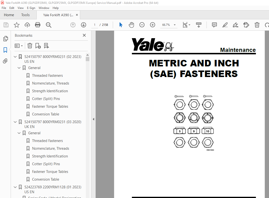
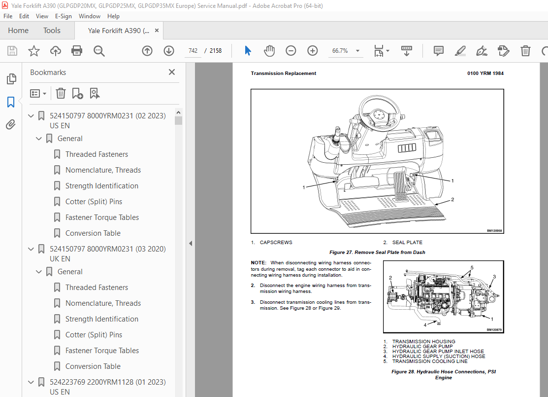
TABLE OF CONTENTS:
Yale Forklift A390 (GLPGDP20MX, GLPGDP25MX, GLPGDP35MX Europe) Service Manual – PDF DOWNLOAD
524150797 8000YRM0231 (02 2023) US EN 1
General 7
Threaded Fasteners 7
Nomenclature, Threads 7
Strength Identification 8
Cotter (Split) Pins 9
Fastener Torque Tables 14
Conversion Table 16
524150797 8000YRM0231 (03 2020) UK EN 23
General 27
Threaded Fasteners 27
Nomenclature, Threads 27
Strength Identification 28
Cotter (Split) Pins 29
Fastener Torque Tables 34
Conversion Table 36
524223769 2200YRM1128 (01 2023) US EN 43
Series Code / Model Designation Reference Table 51
General 53
Deutsch Crimping Tool 54
How to Strip a Wire for Use With Deutsch Crimping Tool 54
How to Crimp With the Deutsch Crimping Tool 55
Calibration Test for the Deutsch Crimping Tool 57
Deutsch Connectors 59
DT, DTM, and DTP Series Connectors 59
HD Series Connectors 102
Metri-Pack Connectors 124
Remove and Install 124
Micro-Pack Connectors 127
Weather-Pack Connectors 128
AMPSEAL Crimping Tools 130
AMP Hand Crimping Tool With Certi-Crimp 130
Description 130
Stripping Wire for Use with AMP Hand Crimping Tool 131
Insulation Crimp Adjustment 132
Maintenance and Inspection for AMP Hand Crimping Tool 132
AMP Hand Crimping Tool 132
Crimp Height Inspection 132
How to use AMP Hand Crimping Tool 133
AMP Pro-Crimper II Tool 133
Description 133
Remove and Install Die Set and Locator Assembly 134
Stripping Wire for Use With AMP PRO-CRIMPER II Tool 134
Contact Support Adjustment 135
Crimp Height Adjustment 136
Maintenance and Inspection Procedures 136
PRO-CRIMPER II Tool 136
Crimp Height Inspection 136
How to Use AMP PRO-CRIMPER II Tool 137
AMPSEAL Connector Assemblies 138
Description for Plug Connector Assembly 138
Seal Plug 139
Contact Crimping 139
Description for Plug Connector and Header Assembly 144
Voltage Reading 147
Seal Plug 147
Contact Crimping 147
AMP Superseal 1 5 Crimping Tools 154
Mini Mic Receptacle and Tab Contacts 154
Description 154
Crimping Conditions and Measurements 154
Insertion of Rubber Seal on Cable 156
AMP Hand Application Tool 161
Description 161
Maintenance and Inspection 161
Crimp Height Inspection 161
Crimp Height Adjustment 162
How to Use AMP Hand Application Tool 162
AMP Pro-Crimper II Tool 163
Description 163
Remove and Install Die Set and Locator Assembly 163
Adjustments 164
Contact Support 164
Crimp Height 165
Inspections and Maintenance 166
Crimp Height Inspection 166
Visual Inspection 166
Maintenance 167
How to Use Pro-Crimper II Tool 167
AMP Superseal 1 5 Connector Assemblies 168
Description 168
Repair and Maintenance 175
Panel Mount Option 175
AMP Fastin-Faston Hand Tools 176
Description – AMP Double Action Hand Tool 176
Maintenance and Inspection Procedures 176
Daily Maintenance 176
Periodic Tool Inspection 177
Lubrication 177
Visual Inspection 177
Crimp Height Inspection 177
Certi-Crimp Ratchet Inspection 178
How to Use AMP Double Action Hand Tool 179
Description – AMP Extraction Tool 180
Maintenance and Inspection 181
How to Use AMP Extraction Tool 181
AMP Fastin-Faston Receptacles and Housings 183
Description 183
Wire Repair 191
Wire Splicing Requirements 191
Deutsch Jiffy Splice 192
Twisted/Shielded Cable and Leads Repair 198
Special Tools 200
524223769 2200YRM1128 (07 2020) UK EN 209
Series Code / Model Designation Reference Table 215
General 218
Deutsch Crimping Tool 218
How to Strip a Wire for Use With Deutsch Crimping Tool 218
How to Crimp With the Deutsch Crimping Tool 219
Calibration Test for the Deutsch Crimping Tool 221
Deutsch Connectors 223
DT, DTM, and DTP Series Connectors 223
HD Series Connectors 265
Metri-Pack Connectors 288
Remove and Install 288
Micro-Pack Connectors 290
Weather-Pack Connectors 291
AMPSEAL Crimping Tools 293
AMP Hand Crimping Tool With Certi-Crimp 293
Description 293
Stripping Wire for Use with AMP Hand Crimping Tool 293
Insulation Crimp Adjustment 294
Maintenance and Inspection for AMP Hand Crimping Tool 294
AMP Hand Crimping Tool 294
Crimp Height Inspection 294
How to use AMP Hand Crimping Tool 295
AMP Pro-Crimper II Tool 295
Description 295
Remove and Install Die Set and Locator Assembly 296
Stripping Wire for Use With AMP PRO-CRIMPER II Tool 297
Contact Support Adjustment 297
Crimp Height Adjustment 298
Maintenance and Inspection Procedures 298
PRO-CRIMPER II Tool 298
Crimp Height Inspection 298
How to Use AMP PRO-CRIMPER II Tool 299
AMPSEAL Connector Assemblies 300
Description for Plug Connector Assembly 300
Seal Plug 301
Contact Crimping 301
Description for Plug Connector and Header Assembly 306
Voltage Reading 308
Seal Plug 308
Contact Crimping 308
AMP Superseal 1 5 Crimping Tools 315
Mini Mic Receptacle and Tab Contacts 315
Description 315
Crimping Conditions and Measurements 315
Insertion of Rubber Seal on Cable 317
AMP Hand Application Tool 322
Description 322
Maintenance and Inspection 322
Crimp Height Inspection 322
Crimp Height Adjustment 323
How to Use AMP Hand Application Tool 323
AMP Pro-Crimper II Tool 324
Description 324
Remove and Install Die Set and Locator Assembly 325
Adjustments 325
Contact Support 325
Crimp Height 326
Inspections and Maintenance 327
Crimp Height Inspection 327
Visual Inspection 327
Maintenance 328
How to Use Pro-Crimper II Tool 328
AMP Superseal 1 5 Connector Assemblies 329
Description 329
Repair and Maintenance 336
Panel Mount Option 336
AMP Fastin-Faston Hand Tools 337
Description – AMP Double Action Hand Tool 337
Maintenance and Inspection Procedures 337
Daily Maintenance 337
Periodic Tool Inspection 338
Lubrication 338
Visual Inspection 338
Crimp Height Inspection 338
Certi-Crimp Ratchet Inspection 339
How to Use AMP Double Action Hand Tool 340
Description – AMP Extraction Tool 341
Maintenance and Inspection 341
How to Use AMP Extraction Tool 342
AMP Fastin-Faston Receptacles and Housings 343
Description 343
Wire Repair 350
Wire Splicing Requirements 350
Deutsch Jiffy Splice 351
Twisted/Shielded Cable and Leads Repair 356
Special Tools 359
524240453 0600YRM1205 (01 2017) UK EN 367
General 373
Engine Identification 373
Major Engine Component Identification 373
Location of Labels 374
Engine Removal and Installation 375
Cylinder Head Assembly Repair 375
Glow Plugs 378
Remove 378
Install 378
Valve Cover 378
Remove 378
Clean and Inspect 379
Install 379
Rocker Arm Assembly 379
Remove 379
Disassemble 380
Clean and Inspect 381
Push Rods 381
Rocker Arm Assembly 381
Assemble 381
Install 382
Valve Clearance Adjustments 382
Cylinder Head Assembly 383
Remove 383
Disassemble 388
Valves and Valve Springs, Remove 388
Valve Guides, Remove 388
Clean and Inspect 389
Cylinder Head 389
Valve Guides 390
Valves 390
Valve Sink 390
Valve Seat 391
Valve Springs 391
Assemble 392
Valve Guides, Install 392
Valves and Valve Springs, Install 392
Install 393
Timing Gear Case and Timing Gears Repair 394
Timing Gear Case Cover 395
Remove 395
Clean and Inspect 395
Install 396
Timing Gears 396
Crankshaft Gear 397
Remove 397
Install 397
Idler Gear 397
Remove 397
Inspect 398
Install 398
Camshaft Gear 398
Remove 398
Install 399
Timing Gear Case 399
Remove 399
Clean and Inspect 400
Install 400
Drive Train, Camshaft, and Cylinder Block Repair 401
Remove 401
Disassemble 402
Pistons and Connecting Rods 402
Crankshaft 402
Camshaft 405
Clean and Inspect 406
Cylinder Block 406
Honing and Boring 409
Pistons 410
Piston Pin 410
Connecting Rod 411
Tappets 411
Crankshaft 412
Camshaft 413
Camshaft Bushing 414
Assemble 414
Camshaft 414
Crankshaft 414
Pistons and Connecting Rods 415
Install 416
Lubrication System Repair 417
Engine Oil and Oil Filter Change 417
Oil Pan 417
Remove 417
Install 418
Oil Suction Tube 418
Remove 418
Clean 419
Install 419
Oil Pump 419
Remove 419
Clean and Inspect 420
Outer Rotor Outside Clearance 420
Outer Rotor to Inner Rotor Tip Clearance 421
Outer Rotor Side Clearance 421
Rotor Shaft Clearance 421
Install 422
Fuel System Repair 422
Fuel Injectors 423
Remove 423
Inspect 424
Clean 424
Test 424
Install 427
Electronic Throttle System 427
Remove 427
Install 430
Inspect 431
Adjust 432
Manual Throttle System 433
Fuel Injection Pump 433
Remove 433
Clean and Inspect 437
Install 437
Check/Adjust Fuel Injection Timing 438
Cooling System Repair 440
V-Belt 440
Remove 440
Inspect 440
Install 440
Adjust 440
Water Pump 442
4TNE92-NMHA, 4TNE92-NMHA/580090035, 4TNE92-SNMU, and 4TNE98-SNMU Engines 442
Remove 442
Install 443
4TNE92-NMH, 4TNE98-NMH, 4TNE92-NMH/580090036, and 4TNE98-BNMH Engines 444
Remove 444
Install 445
Thermostat 447
Remove 447
Inspect 448
Install 448
Flywheel and Flywheel Housing 448
Flywheel 449
Remove 449
Install 450
Flywheel Housing 450
Remove 450
Install 450
Electrical Equipment Repair 452
Alternator 452
Remove 452
Bench Test 454
Regulate Voltage Check 454
No Load Test 456
Output Test 456
Install 456
Starter 457
Remove 458
No Load Test 458
Install 459
Engine Specifications 460
Engine Data 460
Engine Tuning 468
Cylinder Head 468
Intake/Exhaust Valve and Guide 469
Valve Spring 469
Rocker Arm and Shaft 469
Push Rod 470
Gear Train and Camshaft 470
Camshaft 470
Idle Gear Shaft and Bushing 470
Backlash of Each Gear 471
Cylinder Block 471
Crankshaft 471
Thrust Bearing 472
Piston 472
Piston Ring 472
Connecting Rod 473
Rod Small End 473
Tappet 473
Oil Pump 474
Engine Oil Pressure 474
Outer Rotor Outside Clearance 474
Outer Rotor Side Clearance 474
Outer Rotor to Inner Rotor Tip Clearance 474
Rotor Shaft Clearance 474
Standard Torque Specifications 475
Standard Torque Chart 475
Special Torque Specifications 476
Special Tools 477
550073240 1900YRM1620 (01 2023) US EN 485
Proper Flushing after Major Hydraulic Repairs 491
Introduction 491
The Phases of Wear 491
Causes of Hydraulic System Failure 491
Progression of Contaminant Caused Hydraulic System Failure 492
Hydraulic System Flushing Techniques 492
Double Oil and Filter Change 492
Mechanical Cleaning 493
Cleaning of Components 493
How to Clean Tubes and Hoses 493
Filter Caddy 493
Start-Up Procedure for Cleaned System 494
Contaminated Oil Coolers 494
Additional Filter Caddy Functions 495
How to Handle Different Fluids 495
Water Removal Filters 495
Fluid Conditioning and System Flushing Procedures 496
Operation of the Filter Caddy 496
Filter Caddy operation 496
Fluid Conditioning Procedure 496
Filter Caddy Start-Up 497
System Flushing Procedure 497
Component Cleaning Procedure 498
Reservoir Cleaning Procedure 498
Cylinder Cleaning Procedure 498
Hose and Tube Cleaning Procedure 498
Valve Cleaning Procedure 499
Front-End Attachment Cleaning Procedure 500
System Flushing Procedure 500
Filter Caddy Start-Up 501
System Start-Up and Flushing 501
Reservoir Fluid Cleaning Times 502
Dealing With Different Fluid Types 503
Cleaning Procedure After Switching Fluids (Cross Contamination Flushing) 503
Filter Caddy Maintenance 503
Servicing the Strainer 503
DC Motor 503
Hydraulic Oil Sampling Method and Procedure 504
Hydraulic Oil Sampling Method 504
Objective 504
General Guidelines 504
Synopsis 505
Hydraulic Oil Analysis Report Guidelines 506
Sampling Conditions 506
Equipment 506
Sampling Procedure 507
Hydraulic Oil Sampling 507
Sample Labeling 507
Results Documentation 507
550073240 1900YRM1620 (03 2020) UK EN 509
Proper Flushing after Major Hydraulic Repairs 513
Introduction 513
The Phases of Wear 513
Causes of Hydraulic System Failure 513
Progression of Contaminant Caused Hydraulic System Failure 514
Hydraulic System Flushing Techniques 514
Double Oil and Filter Change 514
Mechanical Cleaning 515
Cleaning of Components 515
How to Clean Tubes and Hoses 515
Filter Caddy 515
Start-Up Procedure for Cleaned System 516
Contaminated Oil Coolers 516
Additional Filter Caddy Functions 516
How to Handle Different Fluids 516
Water Removal Filters 517
Fluid Conditioning and System Flushing Procedures 517
Operation of the Filter Caddy 517
Filter Caddy operation 517
Fluid Conditioning Procedure 518
Filter Caddy Start-Up 518
System Flushing Procedure 519
Component Cleaning Procedure 519
Reservoir Cleaning Procedure 519
Cylinder Cleaning Procedure 519
Hose and Tube Cleaning Procedure 520
Valve Cleaning Procedure 520
Front-End Attachment Cleaning Procedure 521
System Flushing Procedure 521
Filter Caddy Start-Up 522
System Start-Up and Flushing 522
Reservoir Fluid Cleaning Times 523
Dealing With Different Fluid Types 523
Cleaning Procedure After Switching Fluids (Cross Contamination Flushing) 523
Filter Caddy Maintenance 524
Servicing the Strainer 524
DC Motor 524
Hydraulic Oil Sampling Method and Procedure 524
Hydraulic Oil Sampling Method 524
Objective 524
General Guidelines 524
Synopsis 525
Hydraulic Oil Analysis Report Guidelines 526
Sampling Conditions 527
Equipment 527
Sampling Procedure 527
Hydraulic Oil Sampling 527
Sample Labeling 528
Results Documentation 528
550108890 0600YRM1755 (04 2019) UK EN 531
General 537
Engine Removal and Installation 540
Cylinder Head Assembly Repair 540
Drive Train and Lubrication System 579
Remove 580
Disassemble 580
Oil Pan 580
Oil Pump (Front Cover) 583
Clean and Inspect 584
Front Case 584
Oil Seal 584
Counterbalance Shaft 584
Oil Pump 584
Assemble 585
Counterbalance Shaft Bearings 585
Oil Pump (Front Cover) 586
Oil Pan 588
Install 588
Crankshaft and Cylinder Block Repair 589
Remove Major Attaching Components 589
Crankshaft and Cylinder Block 589
Remove 589
Clean and Inspect 590
Boring Cylinder 591
Install 592
Piston and Connecting Rod 594
Remove 594
Disassemble 595
Clean and Inspect 596
Assemble 597
Install 599
Piston 599
Rod Bearing 600
Install Major Attaching Components 601
Fuel System Repair 601
Cooling System Repair 601
Electrical Equipment Repair 602
Flywheel and Flywheel Housing 602
Flywheel 602
Remove 602
Install 603
Flywheel Housing 604
Remove 604
Install 604
Engine Specifications 604
Engine Data 604
Engine Tuning 606
Cylinder Head 606
Intake/Exhaust Valve and Guide 606
Valve Spring 607
Gear Train and Camshaft 607
Camshaft 607
Idle Gear Shaft and Bushing 607
Cylinder Block 607
Crankshaft 607
Piston 608
Piston Ring 608
Connecting Rod 608
Oil Pump 608
Engine Oil Pressure 608
Drive Gear Clearance 608
Driven Gear Clearance 609
Torque Specifications 609
Special Tools 610
550108890 0600YRM1755 (08 2023) US EN 617
General 625
Engine Removal and Installation 629
Cylinder Head Assembly Repair 630
Drive Train and Lubrication System 671
Remove 671
Disassemble 671
Oil Pan 671
Oil Pump (Front Cover) 674
Clean and Inspect 675
Front Case 675
Oil Seal 675
Counterbalance Shaft 675
Oil Pump 675
Assemble 676
Counterbalance Shaft Bearings 676
Oil Pump (Front Cover) 677
Oil Pan 679
Install 679
Crankshaft and Cylinder Block Repair 681
Remove Major Attaching Components 681
Crankshaft and Cylinder Block 681
Remove 681
Clean and Inspect 682
Boring Cylinder 683
Install 684
Piston and Connecting Rod 686
Remove 686
Disassemble 687
Clean and Inspect 687
Assemble 688
Install 690
Piston 690
Rod Bearing 691
Install Major Attaching Components 692
Fuel System Repair 693
Cooling System Repair 694
Electrical Equipment Repair 695
Flywheel and Flywheel Housing 696
Flywheel 696
Remove 696
Install 697
Flywheel Housing 697
Remove 697
Install 697
POWER TAKE OFF (PTO), REMOVE AND INSTALL 698
REMOVE COVER 698
INSTALL COVER 698
Engine Specifications 700
Engine Data 700
Engine Tuning 701
Cylinder Head 702
Intake/Exhaust Valve and Guide 702
Valve Spring 702
Gear Train and Camshaft 703
Camshaft 703
Idle Gear Shaft and Bushing 703
Cylinder Block 703
Crankshaft 703
Piston 703
Piston Ring 704
Connecting Rod 704
Oil Pump 704
Engine Oil Pressure 704
Drive Gear Clearance 704
Driven Gear Clearance 704
Torque Specifications 705
Special Tools 707
550141704 0100YRM1984 (01 2017) UK EN 711
General 715
Description 715
Hood, Seat, and Side Covers Replacement 717
Remove 717
Install 722
Steering Column 722
Description 723
Steering Column Repair 723
Remove 723
Disassemble 724
Clean 727
Inspect 727
Assemble 727
Install 727
LPG Tank and Bracket Assembly 728
Counterweight Replacement 728
Remove 728
Install 729
Tow Pin 730
Overhead Guard Replacement 730
Remove and Install 730
LED Tail, Backup, and Brake Lights, Replace 731
Operator Restraint System Replacement 732
Description 732
Emergency Locking Retractor (ELR) 732
Engine Replacement 733
Remove 734
Install 740
Transmission Replacement 741
Remove 741
Install Transmission with Aluminum Housing 743
Throttle Pedal and Cable Adjustment 744
PSI Engine with Electronic Throttle 744
Yanmar Diesel Engine With Manual Throttle Cable 745
Traction Speed Limit (TSL) Group 747
Remove 748
Install 750
Adjustment Procedure 750
Exhaust System Repair 751
Lift Trucks With Counterweight Exhaust System 752
Yanmar Diesel Engine 752
Remove and Disassemble 752
Inspect 752
Assemble and Install 752
PSI Engine 754
Remove and Disassemble 754
Inspect 756
Assemble and Install 756
Lift Trucks With Overhead Exhaust System 757
Yanmar Diesel Engine 757
Remove and Disassemble 757
Inspect 759
Assemble and Install 759
PSI Engine 760
Remove and Disassemble 760
Inspect 763
Assemble and Install 763
Cooling System 764
Description 764
Diesel Fuel Level Sender 764
Remove 764
Install 765
Hydraulic Filter Assembly Repair 765
Remove 765
Clean and Inspect 766
Install 767
Fuel and Hydraulic Tanks Repair 768
Inspect 768
Clean 768
Steam Method of Cleaning 768
Chemical Solution Method of Cleaning 769
Additional Preparations for Repair 770
Small Leaks, Repair 770
Large Leaks, Repair 770
Preparations for Use After Repair 770
Safety Labels 771
550141705 0100YRM1985 (07 2016) UK EN 777
General 781
Cab Replacement 781
Remove 781
Install 787
Cab Doors 788
Remove 788
Disassemble 788
Right Cab Door 788
Left Cab Door 789
Clean 791
Inspect 791
Assemble 791
Right Cab Door 791
Left Cab Door 791
Install 791
Window Wipers Replacement 791
General 791
Front Wiper and Motor Assembly 791
Remove 791
Clean 792
Inspect 792
Install 793
Rear Wiper and Motor Assembly 793
Remove 793
Clean 794
Inspect 794
Install 794
Window Replacement 795
General 795
Front Window 795
Remove 795
Clean 796
Inspect 797
Install 797
Rear Window 797
Remove 797
Clean 798
Inspect 798
Install 798
Door Window 799
Remove and Disassemble 799
Clean 801
Inspect 801
Assemble and Install 801
Top Window 801
PVC Top Window 801
Remove 802
Clean 802
Inspect 802
Install 802
Glass Top Window 802
Remove 802
Clean 803
Inspect 803
Install 803
Cab Heater Replacement 804
Remove 804
Install 805
Cab Heater Filter 805
Remove 805
Install 805
Cab Heater Operation 806
Lights Replacement 806
Optional Equipment 807
Heavy Duty Pre-Cleaner 807
Remove 807
Clean 808
Inspect 808
Install 808
Mirror 808
Remove 808
Install 808
Rear Horn Button and Handle 808
Label Replacement 808
Electrical Schematics 809
Dash Display Panel and Switches 809
550141706 0700YRM1986 (07 2016) UK EN 813
General 817
Cooling System Checks 817
Exhaust Leaks Into Cooling System 817
Water Flow Restrictions in Radiator 817
Radiator Hoses 817
Water Pump 818
Flushing the Cooling System 818
Cooling System, Clean 818
Radiator Replacement 819
Radiator, Remove 819
Radiator, Install 825
Fan Assembly Replacement 826
Fan Removal 826
Inspect 827
Fan Installation 827
550141707 0900YRM1987 (04 2018) UK EN 831
General 835
Intake-Air System 835
Intake-Air System Manifold Vacuum Check 835
Throttle Body 836
Remove 837
Install 837
Intake Manifold 837
LPG Tank and Bracket Replacement with Swing-Out Bracket 837
Remove LPG Tank 837
Install LPG Tank 839
Remove LPG Bracket 839
Install LPG Bracket 840
Remove LPG Tank Bracket Alignment Pin 841
Install LPG Tank Bracket Alignment Pin 842
LPG Tank and Bracket Replacement with Fixed Bracket 842
Remove LPG Tank 842
LPG Tank Install 843
Remove LPG Bracket 843
Install LPG Bracket 843
LPG Fuel Filter Unit Repair 845
Fuel Filter Element 845
Remove 845
Clean/Inspect 845
Install 846
Fuel Filter Housing 846
Remove 846
Disassemble 846
Assemble 848
Install 848
Electronic Throttle Body Repair 848
Remove 849
Install 849
LPG Fuel Mixer With Direct Electronic Pressure Regulator (DEPR) Repair 852
Remove 852
Install 853
Gasoline Fuel System 854
Before Repair Procedure 855
Fuel Line Safety Procedure 855
After Repair Procedure 856
Fuel Hose, Install 856
Fuel Leakage Check 857
Fuel Line Pressure Check 857
Fuel Injectors 857
Remove 857
Install 857
Pressure Regulator 858
Remove 858
Install 858
Control System 859
Engine Control Module (ECM) 859
Remove 859
Install 859
Fuel Level Sensor 860
Remove 860
Install 860
Low LPG Pressure Switch 861
Remove 861
Install 861
LPG Converter 862
LPG Lock-Off Valve 865
Remove 865
Install 866
Exhaust System 868
Counterweight Exhaust System 868
Remove and Disassemble 868
Inspect 868
Assemble and Install 868
Overhead Exhaust System 870
Remove and Disassemble 870
Inspect 872
Assemble and Install 872
Exhaust Manifold 872
Positive Crankcase Ventilation (PCV) Valve 872
Remove 872
Inspect 873
Install 873
Oxygen Sensor 873
Remove 873
Install 873
LPG Fuel Testing 874
General 874
Available Fuel Tests 875
Composition Test (ASTM D-2163) 875
Ammonia Test (ASTM D-4490) 875
Basic Nitrogen Test (ASTM UOP269-90) 875
Residues Test (ASTM D-2158) 875
Vapor Pressure Test (ASTM D-2598) 875
Sulfur Compounds Test (ASTM D-5623) 875
Methanol Test (ASTM D-4864) 875
Copper Corrosion (ASTM D-1838) 875
Where To Send LPG Fuel Samples For Testing 875
Technical Data 876
550141708 1300YRM1988 (10 2016) UK EN 879
General 883
Serial Number 884
Charge Pump Repair 884
Remove 884
Clean 885
Inspect 885
Install 886
Torque Converter Repair 886
Remove 886
Clean and Inspect 890
Install 890
Clutch Packs Repair 892
Remove 892
Disassemble 894
Clean 905
Inspect 905
Assemble 906
Install 918
Control Valve and Solenoid Valve Repair 920
Remove 920
Disassemble 921
Clean 921
Inspect 921
Assemble 922
Install 922
Foot Directional Control Pedal Repair 924
Remove and Disassemble 924
Clean and Inspect 927
Assemble and Install 927
550141709 1400YRM1989 (06 2019) UK EN 931
General 935
Drive Axle Repair 935
Remove and Disassemble 935
Clean and Inspect 937
Assemble and Install 937
Differential Repair 938
Remove 939
Disassemble 946
Clean and Inspect 953
Install 960
Pinion Inner Shim Set, Adjust Thickness (Depth of Pinion) 960
Ring Gear Backlash, Adjust 970
Ring Gear, Runout Check 972
Gear Set, Tooth Contact Pattern Check 972
Drive Axle Repair, Lift Truck Models GP20-25MX (GP040-050MX) After 17 October 2018 974
Remove and Disassemble 975
Clean and Inspect 977
Assemble and Install 977
Differential Repair, Lift Truck Models GP20-25MX (GP040-050MX) After 17 October 2018 979
Remove 979
Disassemble 986
Clean and Inspect 990
Install 996
Pinion Inner Shim Set, Adjust Thickness (Depth of Pinion) 996
Ring Gear Backlash, Adjust 1006
Ring Gear, Runout Check 1007
Gear Set, Tooth Contact Pattern Check 1008
Torque Specifications 1010
550141710 1600YRM1990 (10 2018) UK EN 1013
General 1017
Steering Axle Assembly Repair 1017
Remove 1018
Disassemble 1018
Clean 1019
Inspect 1019
Assemble 1020
Install 1020
Spindles, Bearings, and Tie Rods Repair 1020
Spindles and Bearings 1021
Tie Rods 1023
Steering Cylinder Repair 1025
Remove and Disassemble 1026
Clean and Inspect 1026
Assemble and Install 1026
Bearing Press and Needle Bearing Tools 1027
Install 1027
Pre-Installation Instructions 1027
Keeping Needle Bearings Rust Free 1027
Mechanical and Hydraulic Presses 1028
550141711 1800YRM1991 (12 2017) UK EN 1031
General 1035
Dry Brake System 1035
Service Brakes Repair 1035
Remove and Disassemble 1036
Clean 1040
Inspect 1041
Assemble and Install 1041
Adjust 1047
Parking Brake Repair 1047
Remove and Disassemble 1047
Assemble and Install 1047
Adjust 1048
Master Cylinder Repair 1048
Remove 1049
Disassemble 1050
Clean and Inspect 1051
Assemble 1051
Bench Bleed Master Cylinder 1051
Install and Adjust 1051
Service Brakes Adjustment 1052
Brake System Air Removal 1053
Using Pressure Bleed System 1053
Using Brake Pedal Pressure 1053
Brake Pedal Adjustment with Single Pedal Option 1053
Brake Pedal Adjustment with Dual Pedal Option 1054
550141712 1900YRM1992 (07 2016) UK EN 1059
General 1063
Hydraulic Gear Pump Repair 1066
Remove 1066
Lift Trucks Equipped With PSI 2 4L Engine and 27 8 cc/rev Gear Pump With Side Ports 1066
Lift Trucks Equipped With Yanmar Diesel Engine and 24 0 cc/rev Gear Pump With Rear Ports 1069
Disassemble 1070
Clean 1072
Inspect 1072
Assemble 1074
Install 1075
Lift Trucks Equipped With PSI Engine and 27 8 cc/rev Gear Pump With Side Ports 1075
Lift Trucks Equipped With Yanmar Diesel Engine and 24 0 cc/rev Gear Pump With Rear Ports 1075
Hydraulic Gear Pump Specifications 1076
Torque Specifications 1076
Hydraulic Gear Pump 1076
550141713 2000YRM1993 (06 2020) UK EN 1079
General 1083
Electro-Hydraulic Main Control Valve, Lift Truck Models GP040-060MX (A390) 1084
Description 1084
Remove 1085
Electro-Hydraulic Control Valve Sections 1090
General 1090
Outlet Control Valve Section 1091
Remove 1091
Disassemble 1091
Clean 1092
Inspect 1092
Assemble 1093
Install 1093
Auxiliary Control Valve Sections 1093
Remove 1093
Disassemble 1094
Clean 1094
Inspect 1095
Assemble 1095
Install 1095
Tilt Control Valve Section 1095
Remove 1095
Disassemble 1095
Clean 1097
Inspect 1097
Assemble 1097
Install 1097
Lift/Lower Control Valve Section 1097
Remove 1097
Disassemble 1097
Clean 1099
Inspect 1099
Assemble 1099
Install 1099
Inlet Control Valve Section 1099
Remove 1099
Disassemble 1100
Clean 1102
Inspect 1102
Assemble 1102
Install 1102
Install 1103
Manual Hydraulic Main Control Valve 1107
Description 1107
Remove 1108
Manual Main Control Valve Sections 1114
General 1114
Outlet Control Valve Section 1115
Remove 1115
Disassemble 1116
Clean 1116
Inspect 1117
Assemble 1117
Install 1117
Auxiliary Control Valve Sections 1117
Remove 1117
Disassemble 1118
Clean 1118
Inspect 1119
Assemble 1119
Install 1119
Tilt Control Valve Section 1119
Remove 1119
Disassemble 1119
Clean 1120
Inspect 1121
Assemble 1121
Install 1121
Lift/Lower Control Valve Section 1121
Remove 1121
Disassemble 1121
Clean 1122
Inspect 1123
Assemble 1123
Install 1123
Inlet Control Valve Section 1123
Remove 1123
Disassemble 1123
Clean 1125
Inspect 1126
Assemble 1126
Install 1126
Install 1126
Pressure Relief Valve Check and Adjustment 1132
General 1132
Main Relief Valve 1133
Secondary Relief Valve 1134
Steering Relief Valve 1134
Main Control Valve Specifications 1135
Electro-Hydraulic Main Control Valve 1135
Manual Main Control Valve 1136
550141714 2100YRM1994 (02 2018) UK EN 1139
General 1143
Safety Procedures When Working Near Mast 1144
Main Lift Cylinder Repair 1146
Remove 1146
Disassemble 1148
Clean 1150
Inspect 1150
Assemble 1150
Install 1151
Main Lift Cylinder Leak Check 1151
Free-Lift Cylinder 1152
Remove 1152
Disassemble 1153
Clean 1155
Inspect 1155
Assemble 1155
Install 1155
Tilt Cylinder Repair 1156
Remove 1156
Disassemble 1157
Clean 1158
Inspect 1158
Assemble 1158
Install 1159
Tilt Cylinder Adjustment 1159
Tilt Cylinder Leak Check 1160
Integral Sideshift Cylinder Repair Prior to December 2016 1161
Remove 1161
Disassemble 1162
Clean 1163
Inspect 1163
Assemble 1163
Install 1163
Integral Sideshift Cylinder Repair After December 2016 1164
General 1164
Remove 1164
Disassemble 1164
Clean 1165
Inspect 1165
Assemble 1165
Install 1166
Integral Side-Shift Cylinder Gland Leak Checks 1166
Fork Positioner Cylinder Repair Prior to December 2016 1167
Remove 1167
Disassemble 1167
Clean 1170
Inspect 1171
Assemble 1171
Install 1171
Fork Positioner Cylinder Adjustment 1171
Fork Positioner Cylinder Repair After December 2016 1172
General 1172
Remove 1172
Disassemble 1172
Clean 1175
Inspect 1175
Assemble 1176
Install 1176
Fork Positioner Cylinder Adjustment 1176
Seal Kit Installation 1176
External Installation (Seal and Backup Ring) 1177
Internal Installation (Piston Rod Assembly) 1177
Torque Specifications 1178
Main Lift Cylinders 1178
Free-Lift Cylinder 1178
Tilt Cylinders 1178
Integral Sideshift Cylinder 1178
Fork Positioner Cylinder 1178
550141716 2200YRM1996 (03 2019) UK EN 1181
General 1185
Description 1185
Dash Display Menu Access 1185
Menu Navigation 1186
Standard Display 1186
Main Menu 1186
Passwords 1186
Adding Passwords 1187
Hourmeters 1187
Instrument Panel Display Functions 1188
Digital Clock 1188
Speedometer 1189
Lift Truck Controller 1190
Load Meter 1190
Truck Configuration 1191
Diagnostics 1191
View Fault Log 1191
Controller Error Code 1191
Display Error Code 1192
Clear Error Codes 1192
Speed Settings 1193
Speed Limit 1193
Setup Hydraulics, Lift Truck Models GP040-060MX (A390) 1194
Electronic Hydraulics (E-Hydraulics) 1194
Setup Display Menu 1194
Setup General Items 1194
Seat Belt Alarm 1194
Parking Alarm 1195
Leaving Seat Warning Function 1195
Key Switch OFF Reminder 1195
Calibrations 1195
550141717 2200YRM1997 (07 2019) UK EN 1199
General 1205
Display Panel 1206
Remove 1206
Install 1207
Direction Control and Turn Signal Levers 1207
Remove 1207
Install 1209
Key Switch 1209
Remove 1209
Install 1210
Steering Column Repair 1211
Remove 1211
Disassemble 1213
Assemble 1214
Install 1214
Sensors and Switches 1215
General 1215
Dash and Kick Panel, Remove and Install 1215
Remove 1215
Install 1215
Brake Fluid Level Switch 1216
Remove 1216
Install 1217
Stop Lamp Switch 1218
Remove 1218
Return To Set Tilt (RTST) Sensor 1218
Remove 1218
Install 1218
Accelerator Pedal Position Sensor 1218
Remove 1218
Install 1219
Parking Brake Sensor 1219
Remove 1219
Install 1220
Service Brake Pressure Switch 1220
Remove 1220
Install 1221
Drive Axle Speed Sensor 1221
Lift Trucks Equipped With A PSI Engine 1221
Remove 1221
Install 1221
Lift Trucks Equipped With Yanmar Diesel Engine 1223
Remove 1223
Install 1223
Sensor MicroswitchFoot Directional Control 1223
Remove 1223
Install 1225
Seat Sensor (Operator Presence System) 1225
Non-Suspension and Semi-Suspension Seats 1225
Remove 1225
Install 1226
Full Suspension Seat 1227
Remove 1227
Install 1227
Seat Belt Interlock Control Module 1228
Remove 1228
Install 1228
Transmission Temperature Switch 1229
Remove 1229
Install 1230
Remote Key Switch 1230
Remove 1230
Install 1230
Load Weight Sensor 1231
Remove 1231
Install 1231
Fuel Level Sensor, Gas Engine Only 1232
Rear Horn Button Switch 1232
Remove 1232
Install 1232
Engine and Fuel Sensors and Switches, Gas and LPG Trucks Equipped With PSI 2 4L Dual Fuel Engine 1233
Engine and Fuel Sensors and Switches, Yanmar 2 6L and 3 3L Diesel Engines 1233
Air Filter Restriction Switch 1233
Remove 1233
Install 1233
Engine Oil Pressure Switch 1233
Remove 1233
Install 1233
Engine Coolant Temperature (ECT) Sensor 1234
Remove 1234
Install 1234
Fuel/Water Separator 1234
Remove 1234
Install 1234
Glow Plugs 1235
Dash Panel Rocker Switches 1235
Remove 1235
Install 1235
Power Distribution Module (PDM) and Component Parts (Fuses and Relays) 1236
Remove 1236
PDM as a Unit 1236
Install 1237
PDM as a Unit 1237
Remove and Install 1237
PDM Component Parts 1237
Battery 1239
Remove 1239
Install 1239
Electronic-Hydraulic Controls, Lift Truck Models GP040-060MX (A390) 1239
E-Hydraulic Controls – TEST 1239
Mini-Levers 1239
Full Stroke Test 1239
Function Returns to Neutral Test 1239
Push Button Switch 1240
General 1240
Mini-levers, Remove and Install 1241
Armrest Assembly 1242
Remove 1242
Install 1244
Horn Button 1244
Remove 1244
Install 1244
Direction Control Switch 1244
Remove 1244
Install 1245
Momentary Switches 1245
Remove 1246
Install 1246
Lights 1247
Work Lights (Front and Rear) 1247
Halogen Bulb Lights 1247
Remove 1247
Install 1247
LED Lights 1247
Remove 1247
Install 1248
Strobe Light 1248
Remove 1248
Install 1248
LED Tail, Backup, and Brake Lights 1249
Remove 1249
Install 1249
LED Front Marker/Turn Signal Lights 1250
Remove 1250
Install 1250
Blue Spot Light (LED) 1251
Remove 1251
Install 1251
Vehicle Electronic Control Unit (VECU) 1252
General 1252
Remove 1252
Install 1253
Horn, Alarms, and Buzzers 1254
Horn 1254
Remove 1254
Install 1254
LPG/Bi-Fuel Warning Buzzer 1254
Remove 1254
Install 1255
Audible Alarm 1255
Remove 1255
Install 1255
Telemetry Wireless Asset Management System 1256
General 1256
Communication Module 1260
Basic Operations 1260
ID Card / ID Reader 1260
Interlock Relay 1261
Buzzer 1261
Wakeup 1261
Checklist 1262
Level 1 – Wireless Monitoring (WIFI Group) 1262
Remove Communication Module 1262
Install Communication Module 1265
Install the Power Harness 1265
Remove Antenna 1266
Install Antenna 1268
Level 2 – Wireless Access 1268
Communication Module 1268
Power Harness 1269
Remove 1269
Install 1269
RF-ID Reader 1271
Remove 1271
Install 1272
Buzzer 1272
Remove 1272
Install 1272
Level 3 – Wireless Verification 1273
Communication Module 1273
Antenna 1273
RF-ID Reader 1274
Buzzer 1274
Display Harness 1274
Remove 1274
Install 1274
Display Panel (Checklist) 1275
Remove 1275
Install 1276
550141718 2200YRM1998 (07 2016) UK EN 1279
General 1283
Ignition System 1283
Ignition Timing Adjustment 1283
Spark Plugs Check 1283
Coil Replacement 1284
Remove 1284
Inspect 1285
Install 1285
Starter Repair 1286
General 1286
Remove 1287
No-Load Test 1288
Magnetic Switch Test 1289
Pull-Out Test 1289
Holding Coil Test 1289
Return Test 1289
Pinion Movement Inspection 1290
Install 1290
Alternator Repair 1290
General 1290
Charging System Inspection 1291
Output Current Check 1291
No-Load Adjusted Voltage Check 1292
Remove 1292
Install 1292
Engine Sensors and Switches 1293
Oil Pressure Sensor 1293
Remove 1293
Install 1294
Air Filter Restriction Switch 1294
Remove 1294
Install 1294
Cam Angle Sensor 1294
Remove 1294
Install 1295
Crankshaft Position Sensor (CKP) 1295
Remove 1295
Install 1295
Temperature Manifold Absolute Pressure (TMAP) Sensor 1296
Remove 1296
Install 1297
Engine Coolant Temperature (ECT) Sensor 1297
Remove 1297
Install 1297
Temperature Sender 1297
Remove 1297
Install 1297
Electronic Control Module 1298
550141719 4000YRM1999 (06 2019) UK EN 1301
General 1307
Safety Procedures When Working Near Mast 1308
Fork Replacement 1310
Standard Carriage and Integral Sideshift Carriage 1310
Remove 1310
Install 1312
Checks 1312
Fork Positioner Carriage 1314
Remove 1314
Install 1315
Checks 1316
Carriages Repair, Two-Stage LFL Mast Prior to December, 2016 1316
Standard Carriage 1316
Remove 1316
Clean and Inspect 1317
Install 1318
Integral Sideshift Carriage 1318
Remove 1318
Disassemble 1320
Clean and Inspect 1321
Assemble 1322
Install 1322
Fork Positioner Carriage 1323
Remove 1323
Clean and Inspect 1325
Install 1325
Fork Positioner Hydraulic Hose Adjustment 1327
Carriages Repair, Two-Stage LFL Mast, December, 2016 to Late June, 2018 1328
Standard Carriage 1328
Remove 1328
Clean and Inspect 1329
Install 1330
Integral Sideshift Carriage 1330
Remove 1330
Disassemble 1332
Clean and Inspect 1333
Assemble 1334
Install 1334
Fork Positioner Carriage 1335
Remove 1335
Disassemble and Assemble 1337
Clean and Inspect 1337
Install 1337
Fork Positioner Hydraulic Hose Adjustment 1338
Carriages Repair, Two-Stage LFL Mast, Late June, 2018 and After 1339
Standard Carriage 1339
Remove 1339
Clean and Inspect 1340
Install 1341
Integral Sideshift Carriage 1341
Remove 1341
Disassemble 1343
Clean and Inspect 1344
Assemble 1345
Install 1345
Fork Positioner Carriage 1346
Remove 1346
Disassemble and Assemble 1348
Clean and Inspect 1348
Install 1348
Fork Positioner Hydraulic Hose Adjustment 1349
Two-Stage LFL Mast Repair 1350
Mast With Serial Numbers A389 and A399 1350
Remove 1352
Disassemble 1354
Clean and Inspect 1359
Assemble 1361
Install 1362
Header Hoses 1363
Remove 1363
Installation 1363
Adjustment 1367
Carriages Repair, Three-Stage FFL Mast Prior To December, 2016 1368
Standard Carriage 1368
Remove 1368
Clean and Inspect 1370
Install 1370
Integral Sideshift Carriage 1370
Remove 1370
Disassemble 1372
Clean and Inspect 1373
Assemble 1374
Install 1374
Fork Positioner Carriage 1375
Remove 1375
Clean and Inspect 1377
Install 1377
Fork Positioner Hydraulic Hose Adjustment 1379
Carriages Repair, Three-Stage FFL Mast, December, 2016 to Late June, 2018 1380
Standard Carriage 1380
Remove 1380
Clean and Inspect 1382
Install 1382
Integral Sideshift Carriage 1382
Remove 1382
Disassemble 1384
Clean and Inspect 1385
Assemble 1386
Install 1386
Fork Positioner Carriage 1387
Remove 1387
Clean and Inspect 1389
Install 1389
Fork Positioner Hydraulic Hose Adjustment 1390
Carriages Repair, Three-Stage FFL Mast, Late June, 2018 and After 1392
Standard Carriage 1392
Remove 1392
Clean and Inspect 1394
Install 1394
Integral Sideshift Carriage 1394
Remove 1394
Disassemble 1397
Clean and Inspect 1398
Assemble 1399
Install 1399
Fork Positioner Carriage 1400
Remove 1400
Clean and Inspect 1402
Install 1402
Fork Positioner Hydraulic Hose Adjustment 1403
Three-Stage FFL Mast Repair 1404
Mast With Serial Numbers A387 And A397 1404
Remove 1406
Disassemble 1408
Clean and Inspect 1416
Assemble 1419
Install 1420
Header Hose Installation and Adjustment 1421
Remove 1421
Installation 1422
Adjustment 1429
Carriage Adjustments 1430
Lift Chains Adjustment 1431
Mast Adjustments 1432
Load Roller, Adjust 1432
Mast Side Kicking, Adjust 1434
Hydraulic Quick Disconnect Hoses 1434
Disconnecting Attachment Hydraulic Quick Disconnect Hoses 1434
Lift Trucks Equipped With E-Hydraulic Controls 1434
Lift Trucks Equipped With Manual Hydraulic Controls 1435
Connecting Attachment Hydraulic Quick Disconnect Hoses 1435
Lift Trucks Equipped With E-Hydraulic Controls 1435
Lift Trucks Equipped With Manual Hydraulic Controls 1436
550141721 8000YRM2001 (02 2019) UK EN 1439
Lift Truck Lifting Capacity 1443
Counterweight Weights 1443
Capacities 1443
Tire Sizes 1446
Electrical System 1446
Transmission Oil Pressures 1447
Hydraulic System Relief Pressures 1448
Steering System 1449
Stall Speeds (in RPM ±100 rpm) 1449
PSI 2 4L 1449
Yanmar 2 6L 1449
Yanmar 3 3L 1449
Mast Speeds 1450
Tilt Angles 1451
Front End Equipment – Mast Creep 1452
Mast Creep 1452
Engine Specifications 1452
Torque Specifications 1453
Frame 1453
Mast 1454
Steering System 1454
Drive Axle 1454
Transmission 1454
Engine – PSI 2 4L LPG or Bi-Fuel 1455
Engine – Yanmar 2 6L and 3 3L Diesel 1456
550141722 8000YRM2002 (04 2019) UK EN 1459
Diagrams and Schematics 1463
Schematics 1463
Wiring Diagram 1486
Hydraulic Schematics 1507
550141723 8000YRM2003 (10 2017) UK EN 1513
Enter Service Mode 1517
Exit Service Mode 1517
Turn Options ON and OFF 1518
Controller Settings 1520
Configure Settings When Replacing the Display 1521
Configure Settings When Replacing the Controller 1521
Set Up the Load Weight Sensor 1522
Set the Truck Speed Limit (PSI Engines Only) 1523
Set the Truck Speed Limit (Yanmar Engines With Manual Throttle) 1523
Turn on Password Requirements 1523
Clear the System Memory 1524
Set up Return-To-Set-Tilt (RTST), Manual Hydraulic Only 1524
Set Up E-Hydraulic Options 1526
Flowcharts 1528
Top Level Menu 1528
Software Version Sub Menus 1529
Maintenance Record Sub Menu 1530
Setting Adjustment 1 Sub Menus 1530
Controller Adjustment Sub Menus 1530
Controller Adjustment – Speed Settings Sub Menus 1531
Controller Adjustment – Operator Compartment Sub Menus 1531
Password Sub Menu 1532
Password Creation Sub Menu 1532
Password ID Sub Menus 1532
Setting Adjustment 4 Sub Menu 1533
Option Adjustment Sub Menus 1533
Maintenance Sub Menus 1534
Controller Error Code Sub Menu 1535
Display Error Code Sub Menu 1535
Error Memory Sub Menus 1536
Display Switch Monitor Sub Menus 1536
Controller Switch Monitor Sub Menus 1538
Output Settings Sub Menu 1539
Data Copy Sub Menus 1540
Copy From Controller to Display Sub Menu 1541
Copy From Display to Controller Sub Menu 1541
Reset Sub Menus 1541
Serial Number Sub Menu 1541
550141724 9000YRM2004 (09 2020) UK EN 1545
SECTION 9010 OPERATIONAL DIAGNOSTIC PROCEDURES 1551
Group 05 – Operational Checkout 1553
SECTION 9020 ENGINE 1563
Group 10 – Principles of Operation 1565
Group 40 – Tests and Adjustments 1609
Group 30 – Observed Symptoms 1617
SECTION 9030 ELECTRICAL SYSTEM 1621
Group 03 – General Maintenance and Diagnostic Data 1625
Group 10 – Principles of Operation 1653
Group 20 – Diagnostic Trouble Codes 1663
Group 30 – Observed Symptoms 1747
SECTION 9040 DRIVE TRAIN 1753
Group 10 – Principles of Operation 1755
Group 30 – Observed Symptoms 1765
Group 40 – Tests and Adjustments 1797
SECTION 9050 HYDRAULIC SYSTEM 1803
Group 10 – Principles of Operation 1807
Group 30 – Observed Symptoms 1837
Group 33 – Observed Symptoms-Gear Pump 1853
Group 43 – Tests and Adjustments-Gear Pump 1939
Group 40 – Tests and Adjustments 1953
SECTION 9060 OPERATORS STATION 1955
Group 10 – Principles of Operation 1957
SECTION 9070 FRONT END (MAST) AND CHASSIS 1975
Group 10 – Principles of Operation 1977
Group 30 – Observed Symptoms 1991
SECTION 9080 SUPPLEMENTARY DATA 2035
Group 50 – Abbreviations and Acronyms 2037
Group 60 – Special Tools List 2045
Group 70 – Fault Mode Indicator Reference 2049
Group 80 – Supplier Specification Data 2051
550141725 8000YRM2000 (10 2019) UK EN 2055
General 2061
Serial Number Data 2061
How to Move Disabled Lift Truck 2061
How to Tow Lift Truck 2061
How to Put Lift Truck on Blocks 2062
How to Raise Drive Tires 2062
How to Raise Steering Tires 2062
How to Clean a Lift Truck 2063
Maintenance Schedule 2064
Maintenance Procedures Every 8 Hours or Daily 2076
How to Make Checks With Engine Stopped 2076
Tires and Wheels 2076
Safety Labels 2076
Mast, Carriage, Lift Chains, Header Hoses, Attachment 2076
Operator Restraint System 2077
Emergency Locking Retractor (ELR) 2078
Adjust Seat – Semi-Suspension 2079
Adjust Seat – Premium Full Suspension 2079
Adjust Seat – Standard Full Suspension 2079
Hood and Seat Latches 2080
Engine Compartment 2081
Fuel, Oil, and Coolant Leaks, Check 2081
Hydraulic Hoses 2081
Coolant Hoses 2081
Steering Column 2081
Transmission 2081
Hydraulic System Oil 2081
Engine Oil 2082
Air Filter 2084
Forks 2084
Remove 2084
Inspect 2086
Install 2087
Adjust 2087
Brake Fluid 2088
How to Make Checks With Engine Running 2088
Indicator Lights, Horn, Fuses, and Relays 2089
Service Brakes 2090
Operation, Check 2090
Parking Brake 2090
Engine Oil Pressure 2091
Cooling System 2091
Steering System 2092
Control Levers and Pedals 2092
Lift System, Operate 2092
First Service After First 100 Hours of Operation 2093
PSI Engine Oil and Oil Filter 2093
Yanmar Engine Oil and Oil Filter 2094
Maintenance Procedures Every 300 Hours 2094
Tie Rod Lubrication 2094
King Pin Lubrication 2094
Maintenance Procedures Every 500 Hours or 1 Year 2095
Hydraulic System Oil 2095
Battery 2096
Yanmar Engine Oil and Oil Filter Change 2096
Drive Belt 2096
Yanmar Diesel Engine 2096
Fan and Alternator Drive Belt 2096
Clean Debris From Radiator Core 2097
Transmission Oil Level 2098
Forks 2098
Mast Lubrication 2099
Header Hose Checks 2101
Lift Chain Lubrication 2101
Tilt Cylinder Lubrication 2101
Master Brake Cylinder Rod End Pin Lubrication 2103
Manual Hydraulic Levers Lubrication 2103
Brake Fluid 2103
Differential and Drive Axle Oil 2104
Maintenance Procedures Every 1000 Hours or 1 Year 2105
Valve Clearance, Check and Adjust, Yanmar Engines 2105
PCV Valve, PSI Engines 2105
Drive Belt Check, PSI Engines 2105
LPG Fuel Filter Replace, PSI Engines 2105
Remove 2105
Clean/Inspect 2106
Install 2106
Gasoline Fuel System, PSI 2 4L Bi-Fuel Engine 2107
Remove and Disassemble 2107
Assembly and Install 2111
Fuel Filter Replacement, Yanmar Engines 2112
Priming the Fuel System, Yanmar 2113
Ignition System 2114
PSI 2 4L Engines 2114
Lift Chains Wear Check 2114
Lift Chain Lubrication 2114
Integral Sideshift Carriage, Check Bearings 2115
Integral Sideshift Carriage, Check Lower Mounting Hooks 2115
Control Levers, Pedals, and Parking Brake 2116
Maintenance Procedures Every 2000 Hours or 1 Year 2116
Hydraulic System 2116
Return Filter, Replace 2116
Air Filter Element, Replace 2118
Air Filter Without Silencer 2118
Air Filter With Silencer 2119
PCV Valve 2121
PSI LPG and Bi-Fuel Engines 2121
Oxygen Sensor 2121
Fuel Injector, Yanmar Engines 2121
Forks, Inspect 2122
Integral Sideshift Carriage 2122
Bearings, Replace 2122
Service Brakes (Dry Brake) 2122
Differential 2123
Transmission Oil and Filter, Replace 2124
Brake Fluid Change, Master Cylinder 2125
Brake Fluid, Remove 2125
Maintenance Procedures Every 4000 Hours or 2 Years 2126
Hydraulic Oil, Replace 2126
Cooling System 2127
Replace Throttle (Accelerator) Cable, Yanmar Diesel Engine 2128
Maintenance Procedures Every 5000 Hours 2128
Fuel Injectors, PSI Engine 2128
Maintenance Procedures Every 6000 Hours 2129
Timing Belt Change, PSI Engine 2129
Safety Procedures When Working Near Mast 2129
Hood Lock Assembly Check 2130
Lift Chain Adjustments 2132
Jump-Starting the Lift Truck 2133
Jump-Starting Using a Battery Charger 2133
Jump-Starting a Lift Truck Using Another Lift Truck 2133
Welding Repairs 2134
Wheel and Tire Replacement 2134
General 2134
Pneumatic Tire With Tube, Repair 2134
Remove Wheels From Lift Truck 2134
Remove Tire From Wheel 2135
Install Wheel in Tire 2137
Install Tire on Two-Piece Wheel 2139
Add Air to Pneumatic Tires With Tube 2140
Install the Wheels 2141
Pneumatic Tubeless Tire, Repair 2141
Remove Wheels From Lift Truck 2141
Add Air to Pneumatic Tubeless Tire 2146
Wheels, Install 2147
Solid Rubber Tires on Pneumatic Wheels, Change 2147
Snap-On-Tire, Change 2151
Easy Mounting Style Solid Rubber Tires on Pneumatic Wheels, Change 2151
Overhead Guard Changes 2157
Adhesives and Sealants 2157
More products