$40.95
Yale Forklift A410 (ERP80VNL6, ERP80VNL9, ERP90VNL) Service Manual PDF
Yale Forklift A410 (ERP80VNL6, ERP80VNL9, ERP90VNL) Service Manual – PDF DOWNLOAD
FILE DETAILS:
Yale Forklift A410 (ERP80VNL6, ERP80VNL9, ERP90VNL) Service Manual – PDF DOWNLOAD
Language : English
Pages : 2603
Downloadable : Yes
File Type : PDF
PART NO. 524150797
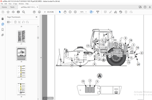
IMAGES PREVIEW OF THE MANUAL:

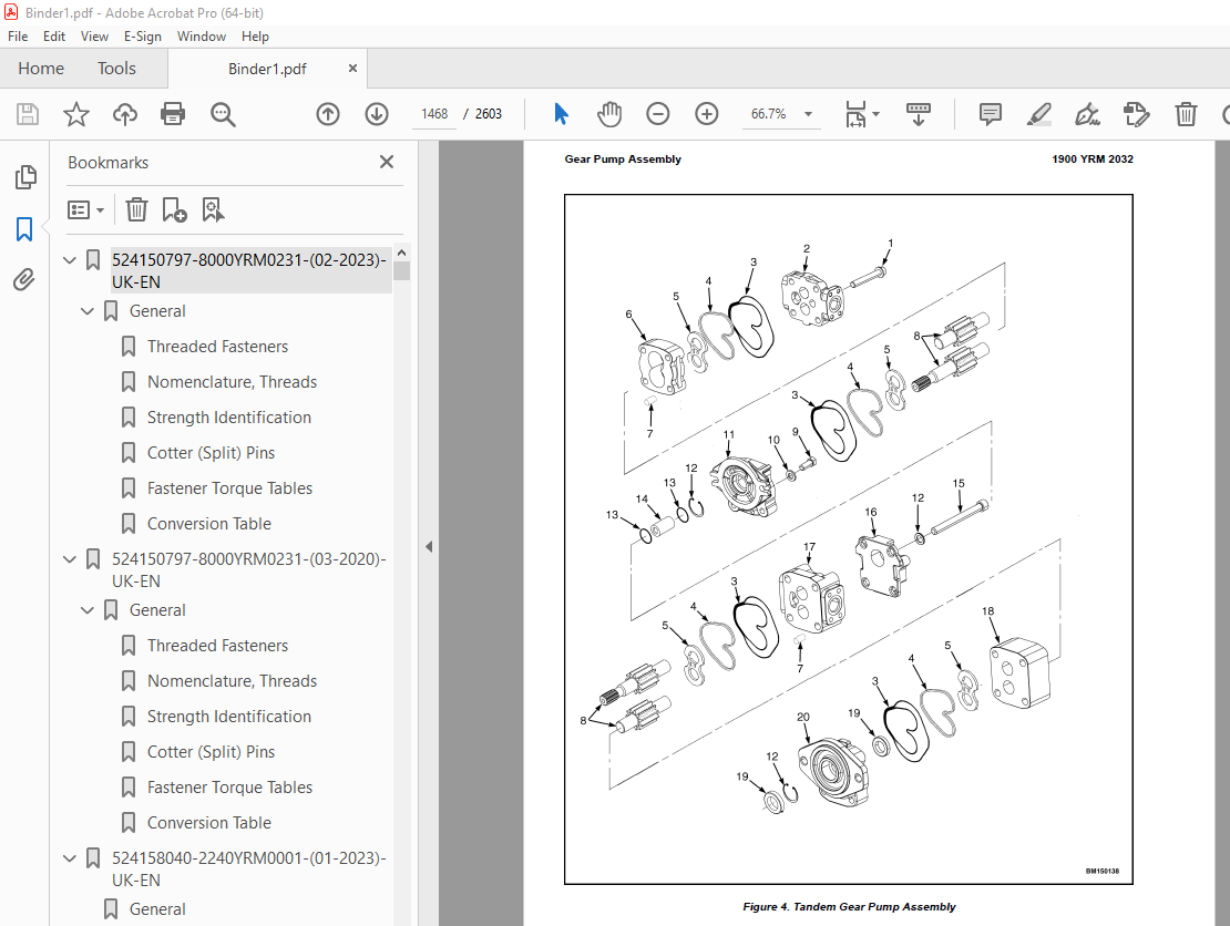
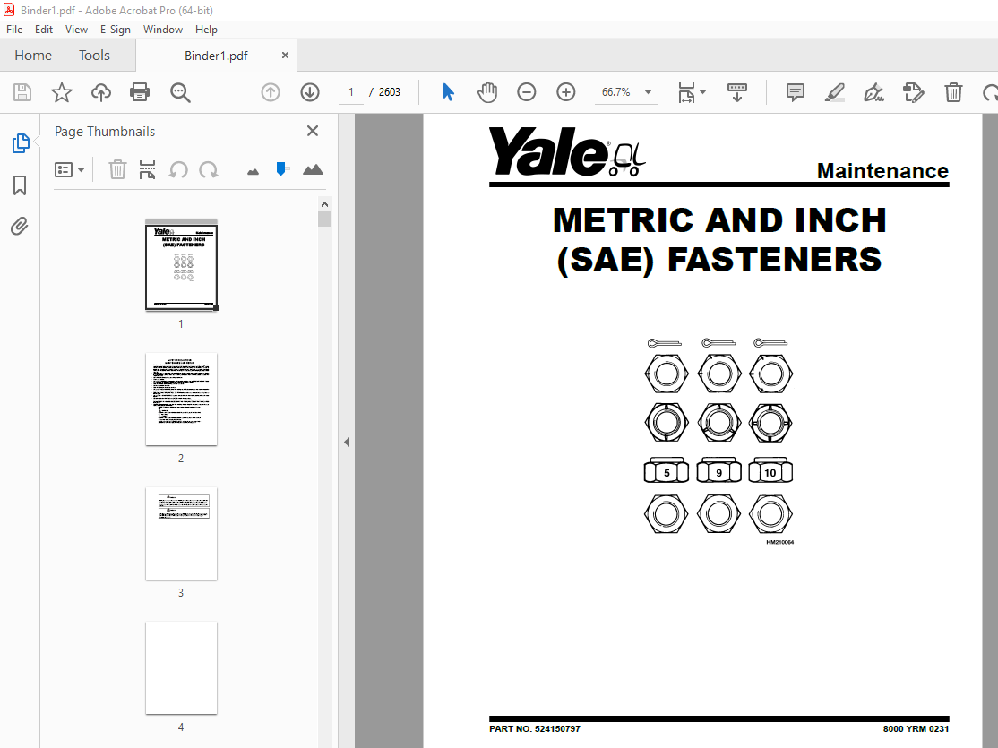
TABLE OF CONTENTS:
Yale Forklift A410 (ERP80VNL6, ERP80VNL9, ERP90VNL) Service Manual – PDF DOWNLOAD
524150797-8000YRM0231-(02-2023)-UK-EN 1
General 7
Threaded Fasteners 7
Nomenclature, Threads 7
Strength Identification 8
Cotter (Split) Pins 9
Fastener Torque Tables 14
Conversion Table 16
524150797-8000YRM0231-(03-2020)-UK-EN 23
General 27
Threaded Fasteners 27
Nomenclature, Threads 27
Strength Identification 28
Cotter (Split) Pins 29
Fastener Torque Tables 34
Conversion Table 36
524158040-2240YRM0001-(01-2023)-UK-EN 43
General 49
Battery Type 49
Lead-Acid Batteries 49
Lithium-Ion Batteries 50
Specific Gravity 50
Chemical Reaction in a Cell 50
Electrical Terms 52
Battery Selection 53
Battery Voltage 54
Battery as a Counterweight 54
Battery Ratings 54
Kilowatt-Hours 54
Battery Maintenance 55
Safety Procedures 55
Maintenance Records 55
New Battery 55
Cleaning Battery 56
Adding Water to Battery 58
Hydrometer 58
Battery Temperature 59
Charging Battery 60
Types of Battery Charges 61
Methods of Charging 62
Troubleshooting Charger 63
Knowing When Battery Is Fully Charged 63
Where to Charge Batteries 63
Equipment Needed 63
Battery Connectors 64
Battery Care 64
Troubleshooting 66
524158040-2240YRM0001-(03-2020)-UK-EN 71
General 75
Battery Type 75
Lead-Acid Batteries 75
Lithium-Ion Batteries 76
Specific Gravity 76
Chemical Reaction in a Cell 76
Electrical Terms 78
Battery Selection 78
Battery Voltage 79
Battery as a Counterweight 80
Battery Ratings 80
Kilowatt-Hours 80
Battery Maintenance 80
Safety Procedures 80
Maintenance Records 81
New Battery 81
Cleaning Battery 81
Adding Water to Battery 83
Hydrometer 84
Battery Temperature 85
Charging Battery 86
Types of Battery Charges 86
Methods of Charging 88
Troubleshooting Charger 88
Knowing When Battery Is Fully Charged 89
Where to Charge Batteries 89
Equipment Needed 89
Battery Connectors 90
Battery Care 90
Troubleshooting 92
524223769-2200YRM1128-(07-2020)-UK-EN 97
Series Code / Model Designation Reference Table 103
General 106
Deutsch Crimping Tool 106
How to Strip a Wire for Use With Deutsch Crimping Tool 106
How to Crimp With the Deutsch Crimping Tool 107
Calibration Test for the Deutsch Crimping Tool 109
Deutsch Connectors 111
DT, DTM, and DTP Series Connectors 111
HD Series Connectors 153
Metri-Pack Connectors 176
Remove and Install 176
Micro-Pack Connectors 178
Weather-Pack Connectors 179
AMPSEAL Crimping Tools 181
AMP Hand Crimping Tool With Certi-Crimp 181
Description 181
Stripping Wire for Use with AMP Hand Crimping Tool 181
Insulation Crimp Adjustment 182
Maintenance and Inspection for AMP Hand Crimping Tool 182
AMP Hand Crimping Tool 182
Crimp Height Inspection 182
How to use AMP Hand Crimping Tool 183
AMP Pro-Crimper II Tool 183
Description 183
Remove and Install Die Set and Locator Assembly 184
Stripping Wire for Use With AMP PRO-CRIMPER II Tool 185
Contact Support Adjustment 185
Crimp Height Adjustment 186
Maintenance and Inspection Procedures 186
PRO-CRIMPER II Tool 186
Crimp Height Inspection 186
How to Use AMP PRO-CRIMPER II Tool 187
AMPSEAL Connector Assemblies 188
Description for Plug Connector Assembly 188
Seal Plug 189
Contact Crimping 189
Description for Plug Connector and Header Assembly 194
Voltage Reading 196
Seal Plug 196
Contact Crimping 196
AMP Superseal 1 5 Crimping Tools 203
Mini Mic Receptacle and Tab Contacts 203
Description 203
Crimping Conditions and Measurements 203
Insertion of Rubber Seal on Cable 205
AMP Hand Application Tool 210
Description 210
Maintenance and Inspection 210
Crimp Height Inspection 210
Crimp Height Adjustment 211
How to Use AMP Hand Application Tool 211
AMP Pro-Crimper II Tool 212
Description 212
Remove and Install Die Set and Locator Assembly 213
Adjustments 213
Contact Support 213
Crimp Height 214
Inspections and Maintenance 215
Crimp Height Inspection 215
Visual Inspection 215
Maintenance 216
How to Use Pro-Crimper II Tool 216
AMP Superseal 1 5 Connector Assemblies 217
Description 217
Repair and Maintenance 224
Panel Mount Option 224
AMP Fastin-Faston Hand Tools 225
Description – AMP Double Action Hand Tool 225
Maintenance and Inspection Procedures 225
Daily Maintenance 225
Periodic Tool Inspection 226
Lubrication 226
Visual Inspection 226
Crimp Height Inspection 226
Certi-Crimp Ratchet Inspection 227
How to Use AMP Double Action Hand Tool 228
Description – AMP Extraction Tool 229
Maintenance and Inspection 229
How to Use AMP Extraction Tool 230
AMP Fastin-Faston Receptacles and Housings 231
Description 231
Wire Repair 238
Wire Splicing Requirements 238
Deutsch Jiffy Splice 239
Twisted/Shielded Cable and Leads Repair 244
Special Tools 247
524319497-2200YRM1335-(01-2023)-UK-EN 255
General 263
Description 263
Display Panel Menu Access 263
Menu Flowchart 264
Supervisor Menu Flowchart 264
Menu Navigation 270
Icon Glossary 274
Introduction 274
Soft Key Icons 274
Overlay Icons 275
Icons on System Off Screen and Alert Screens 275
Main Menu Title Screens 279
Submenu Icons Grouped by Menu 281
Operating Screen Icons 281
Password Screen Icons 282
Activity Log Submenu Icons 282
Calibration Submenu Icons 284
Display Submenu Icons 286
Status Submenu Icons 288
Truck Setup Submenu Icons 291
Operating Screen 298
Introduction 298
Performance Mode Controls 299
Status and Warning Icons 299
Battery Discharge Indicator 300
Direction and Parking Brake Indicators 301
Hazard Flashers and Lighting Controls 301
Steer Angle Indicator 301
System Time 301
Load Weight Indicator 301
System Off/Alert Screens 302
Introduction 302
System Off Screen 302
Alert Screens 302
Password Screen 304
Introduction 304
Password Screen 304
Service Technician Password Setup 304
Adding/Removing/Changing Passwords 305
Password Log 308
Activity Log Menu 309
Introduction 309
Operator Checklist Log 310
Password Log 313
Impact Events Log 315
Calibration Menu 317
Introduction 317
Load Weight Calibration 317
Return to Set Tilt Stop Point Calibration 318
E-Hydraulic and Manual Valve Threshold Calibration 318
Steering Wheel Center Point Calibration 319
Steer Axle Position Calibration 319
Steer Axle Center Point Calibration 320
Manual Hydraulics Calibration 321
Display Menu 322
Introduction 322
Set Date and Time Format Menu 322
Set Daylight Saving Time Menu 323
Procedure for Setting Up Automatic Daylight Savings Time 324
Set Time and Date Menu 326
Procedure for Setting Time and Date 326
Set Units Menu 327
Status Menu 328
Introduction 328
VSM Versions 328
Display Versions 329
Truck Serial Number 329
Hour Meters 329
E-Hydraulic Controller Versions 329
Pump Motor Controller Versions 329
Traction Motor Controller 1 Versions 329
Traction Motor Controller 2 Versions 330
Light Controller Versions 330
Impact Sensor Versions 330
Truck Setup Menu 331
Introduction 331
Add/Remove Password 331
Battery Settings 331
Restore Default Settings 332
Motion Alarm 332
Impact Monitor Settings 333
Impact Detection 333
Setting Adjustments 333
Initial Adjustment of Soft and Hard Impact Settings 333
Readjustment of Soft and Hard Impact Settings 333
Auto Power-Off Time Delay 334
Return to Set Tilt 334
Traction Speed Limit 334
Scheduled Maintenance Reminder 335
Minimum Pump Standby Flow Rate 336
Operator Checklist 336
Impact Monitor Shutdown 337
Motor Braking 338
Changing the Motor Braking Settings 338
Steering Wheel Friction and Steering Turns Adjustment 339
How to Adjust Settings 339
Steering Friction Setting 339
Steering Wheel Number of Turns 340
524319497-2200YRM1335-(07-2020)-UK-EN 343
General 349
Description 349
Display Panel Menu Access 349
Menu Flowchart 350
Supervisor Menu Flowchart 350
Menu Navigation 356
Icon Glossary 360
Introduction 360
Soft Key Icons 360
Overlay Icons 361
Icons on System Off Screen and Alert Screens 361
Main Menu Title Screens 365
Submenu Icons Grouped by Menu 367
Operating Screen Icons 367
Password Screen Icons 368
Activity Log Submenu Icons 368
Calibration Submenu Icons 370
Display Submenu Icons 372
Status Submenu Icons 374
Truck Setup Submenu Icons 377
Operating Screen 384
Introduction 384
Performance Mode Controls 384
Status and Warning Icons 385
Battery Discharge Indicator 386
Direction and Parking Brake Indicators 386
Hazard Flashers and Lighting Controls 387
Steer Angle Indicator 387
System Time 387
Load Weight Indicator 387
System Off/Alert Screens 388
Introduction 388
System Off Screen 388
Alert Screens 388
Password Screen 390
Introduction 390
Password Screen 390
Service Technician Password Setup 390
Adding/Removing/Changing Passwords 391
Password Log 394
Activity Log Menu 395
Introduction 395
Operator Checklist Log 395
Password Log 397
Impact Events Log 399
Calibration Menu 401
Introduction 401
Load Weight Calibration 401
Return to Set Tilt Stop Point Calibration 402
E-Hydraulic and Manual Valve Threshold Calibration 402
Steering Wheel Center Point Calibration 403
Steer Axle Position Calibration 403
Steer Axle Center Point Calibration 404
Manual Hydraulics Calibration 405
Display Menu 406
Introduction 406
Set Date and Time Format Menu 406
Set Daylight Saving Time Menu 407
Procedure for Setting Up Automatic Daylight Savings Time 408
Set Time and Date Menu 410
Procedure for Setting Time and Date 410
Set Units Menu 411
Status Menu 412
Introduction 412
VSM Versions 412
Display Versions 413
Truck Serial Number 413
Hour Meters 413
E-Hydraulic Controller Versions 413
Pump Motor Controller Versions 413
Traction Motor Controller 1 Versions 413
Traction Motor Controller 2 Versions 414
Light Controller Versions 414
Impact Sensor Versions 414
Truck Setup Menu 415
Introduction 415
Add/Remove Password 415
Battery Settings 415
Restore Default Settings 416
Motion Alarm 416
Impact Monitor Settings 416
Impact Detection 417
Setting Adjustments 417
Initial Adjustment of Soft and Hard Impact Settings 417
Readjustment of Soft and Hard Impact Settings 417
Auto Power-Off Time Delay 418
Return to Set Tilt 418
Traction Speed Limit 418
Scheduled Maintenance Reminder 419
Minimum Pump Standby Flow Rate 420
Operator Checklist 420
Impact Monitor Shutdown 421
Motor Braking 422
Changing the Motor Braking Settings 422
Steering Wheel Friction and Steering Turns Adjustment 423
How to Adjust Settings 423
Steering Friction Setting 423
Steering Wheel Number of Turns 424
524319498-2200YRM1336-(02-2023)-UK-EN 427
General 435
Description 435
Display Panel Menu Access 435
Menu Flowchart 436
Technician Menu Flowchart 436
Menu Navigation 442
Icon Glossary 446
Introduction 446
Soft Key Icons 446
Overlay Icons 447
Heat Exchange Module Warning Indicator Screen 447
System Off Screen and Alert Screens 448
Main Menu Title Screens 454
Submenu Icons Grouped by Menu 455
Operating Screen Icons 455
Password Screen Icons 457
Activity Log Submenu Icons 457
Calibration Submenu Icons 458
Display Submenu Icons 462
Status Submenu Icons 464
Truck Setup Submenu Icons 467
Diagnostics Submenu Icons 479
Operating Screen 489
Introduction 489
Performance Mode Controls 489
Status and Warning Icons 490
Battery Discharge Indicator 491
Direction and Parking Brake Indicators 491
Hazard Flashers and Lighting Controls 492
Steer Angle Indicator 492
System Time 492
Load Weight Indicator 492
System Off/Alert Screens 493
Introduction 493
System Off Screen 493
Alert Screens 493
Password Screen 495
Introduction 495
Password Screen 495
Service Technician Password Setup 495
Adding/Removing/Changing Passwords 496
Password Log 499
Activity Log Menu 500
Introduction 500
Operator Checklist Log 500
Password Log 502
Impact Events Log 504
Calibration Menu 506
Introduction 506
Load Weight Calibration 506
Return to Set Tilt Stop Point Calibration 507
E-Hydraulic and Manual Valve Threshold Calibration 507
Steering Wheel Center Point Calibration 508
Steer Axle Position Calibration 509
Steer Axle Center Point Calibration 510
Manual Hydraulics Calibration 510
Display Menu 511
Introduction 511
Set Date and Time Format Menu 511
Set Daylight Saving Time Menu 512
Procedure for Setting Up Automatic Daylight Savings Time 513
Set Time and Date Menu 515
Procedure for Setting Time and Date 515
Set Units Menu 516
Status Menu 517
Introduction 517
VSM Versions 517
Display Versions 518
Truck Serial Number 518
Hour Meters 518
E-Hydraulic Controller Versions 518
Pump Motor Controller Versions 518
Traction Motor Controller 1 Versions 518
Traction Motor Controller 2 Versions 519
Light Controller Versions 519
Impact Sensor Versions 519
E-Steer Controller 1 Versions 519
E-Steer Controller 2 Versions 519
Truck Setup Menu 520
Introduction 520
Add/Remove Password 521
Battery Settings 521
Motor Braking 521
Changing the Motor Braking Settings 522
Battery Mode 522
Battery Setup 523
BDI Adjustment Setting 524
Acceleration Rates 525
Hour Meter Initialization 526
Impact Monitor Shutdown 526
Operator Checklist 528
Minimum Pump Standby Flow Rate 528
Scheduled Maintenance Reminder 529
Traction Speed Limit 530
Return to Set Tilt 530
Auto Power-Off Time Delay 531
Impact Monitor Settings 531
Impact Detection 532
Setting Adjustments 532
Initial Adjustment of Soft and Hard Impact Settings 532
Readjustment of Soft and Hard Impact Settings 532
Motion Alarm 532
Lift Hydraulic Function Maximum Speed and Ramp Times 533
Lower Hydraulic Function Maximum Speed and Ramp Times 533
Tilt Forward Hydraulic Function Maximum Speed and Ramp Times 534
Tilt Backward Hydraulic Function Maximum Speed and Ramp Times 534
Auxiliary 1A Hydraulic Function Maximum Speed and Ramp Times 534
Auxiliary 1B Hydraulic Function Maximum Speed and Ramp Times 534
Auxiliary 2A Hydraulic Function Maximum Speed and Ramp Times 534
Auxiliary 2B Hydraulic Function Maximum Speed and Ramp Times 534
Optional Hydraulic Functions 534
Rear Lights Control 535
Restore Default Settings 535
Steering Wheel Friction and Steering Turns Adjustment 536
Navigation 537
How to Adjust Settings 537
Steering Friction 537
Steering Wheel Number of Turns 538
Diagnostics Menu 540
Introduction 540
Fault Code Log 540
Fault Log Details 541
Speedometer 542
Direction Switch 542
Traction Motor 1 Status 543
Traction Motor 2 Status 543
Occupancy Sensor 543
Brake System Sensors 543
Pump Status 544
Hydraulic Control Inputs 545
E-Hydraulic Valves 545
Hydraulic Sensors 546
System Voltages 546
Steering Position Sensors 548
E-Steering Position Sensors 548
Electric Brake 549
Navigation 550
ESS Diagnostics Menus A, B, and C 551
Menu A 551
Menu B 552
Menu C 554
524319498-2200YRM1336-(07-2020)-UK-EN 557
General 563
Description 563
Display Panel Menu Access 563
Menu Flowchart 564
Technician Menu Flowchart 564
Menu Navigation 570
Icon Glossary 574
Introduction 574
Soft Key Icons 574
Overlay Icons 575
Heat Exchange Module Warning Indicator Screen 575
System Off Screen and Alert Screens 576
Main Menu Title Screens 581
Submenu Icons Grouped by Menu 583
Operating Screen Icons 583
Password Screen Icons 584
Activity Log Submenu Icons 584
Calibration Submenu Icons 586
Display Submenu Icons 589
Status Submenu Icons 591
Truck Setup Submenu Icons 595
Diagnostics Submenu Icons 606
Operating Screen 616
Introduction 616
Performance Mode Controls 616
Status and Warning Icons 617
Battery Discharge Indicator 618
Direction and Parking Brake Indicators 619
Hazard Flashers and Lighting Controls 619
Steer Angle Indicator 619
System Time 619
Load Weight Indicator 619
System Off/Alert Screens 620
Introduction 620
System Off Screen 620
Alert Screens 620
Password Screen 622
Introduction 622
Password Screen 622
Service Technician Password Setup 622
Adding/Removing/Changing Passwords 623
Password Log 625
Activity Log Menu 626
Introduction 626
Operator Checklist Log 626
Password Log 628
Impact Events Log 630
Calibration Menu 632
Introduction 632
Load Weight Calibration 632
Return to Set Tilt Stop Point Calibration 633
E-Hydraulic and Manual Valve Threshold Calibration 633
Steering Wheel Center Point Calibration 634
Steer Axle Position Calibration 635
Steer Axle Center Point Calibration 635
Manual Hydraulics Calibration 636
Display Menu 637
Introduction 637
Set Date and Time Format Menu 637
Set Daylight Saving Time Menu 638
Procedure for Setting Up Automatic Daylight Savings Time 639
Set Time and Date Menu 641
Procedure for Setting Time and Date 641
Set Units Menu 642
Status Menu 643
Introduction 643
VSM Versions 643
Display Versions 644
Truck Serial Number 644
Hour Meters 644
E-Hydraulic Controller Versions 644
Pump Motor Controller Versions 644
Traction Motor Controller 1 Versions 644
Traction Motor Controller 2 Versions 645
Light Controller Versions 645
Impact Sensor Versions 645
E-Steer Controller 1 Versions 645
E-Steer Controller 2 Versions 645
Truck Setup Menu 646
Introduction 646
Add/Remove Password 647
Battery Settings 647
Motor Braking 647
Changing the Motor Braking Settings 648
Battery Mode 648
Battery Setup 649
BDI Adjustment Setting 650
Acceleration Rates 651
Hour Meter Initialization 652
Impact Monitor Shutdown 652
Operator Checklist 653
Minimum Pump Standby Flow Rate 654
Scheduled Maintenance Reminder 654
Traction Speed Limit 656
Return to Set Tilt 656
Auto Power-Off Time Delay 656
Impact Monitor Settings 657
Impact Detection 657
Setting Adjustments 657
Initial Adjustment of Soft and Hard Impact Settings 657
Readjustment of Soft and Hard Impact Settings 658
Motion Alarm 658
Lift Hydraulic Function Maximum Speed and Ramp Times 658
Lower Hydraulic Function Maximum Speed and Ramp Times 659
Tilt Forward Hydraulic Function Maximum Speed and Ramp Times 659
Tilt Backward Hydraulic Function Maximum Speed and Ramp Times 659
Auxiliary 1A Hydraulic Function Maximum Speed and Ramp Times 659
Auxiliary 1B Hydraulic Function Maximum Speed and Ramp Times 660
Auxiliary 2A Hydraulic Function Maximum Speed and Ramp Times 660
Auxiliary 2B Hydraulic Function Maximum Speed and Ramp Times 660
Optional Hydraulic Functions 660
Rear Lights Control 660
Restore Default Settings 661
Steering Wheel Friction and Steering Turns Adjustment 661
Navigation 662
How to Adjust Settings 662
Steering Friction 662
Steering Wheel Number of Turns 663
Diagnostics Menu 665
Introduction 665
Fault Code Log 665
Fault Log Details 666
Speedometer 667
Direction Switch 667
Traction Motor 1 Status 667
Traction Motor 2 Status 668
Occupancy Sensor 668
Brake System Sensors 668
Pump Status 669
Hydraulic Control Inputs 669
E-Hydraulic Valves 669
Hydraulic Sensors 670
System Voltages 670
Steering Position Sensors 671
E-Steering Position Sensors 671
Electric Brake 672
Navigation 673
550073240-1900YRM1620-(01-2023)-UK-EN 675
Proper Flushing after Major Hydraulic Repairs 681
Introduction 681
The Phases of Wear 681
Causes of Hydraulic System Failure 681
Progression of Contaminant Caused Hydraulic System Failure 682
Hydraulic System Flushing Techniques 682
Double Oil and Filter Change 682
Mechanical Cleaning 683
Cleaning of Components 683
How to Clean Tubes and Hoses 683
Filter Caddy 683
Start-Up Procedure for Cleaned System 684
Contaminated Oil Coolers 684
Additional Filter Caddy Functions 685
How to Handle Different Fluids 685
Water Removal Filters 685
Fluid Conditioning and System Flushing Procedures 686
Operation of the Filter Caddy 686
Filter Caddy operation 686
Fluid Conditioning Procedure 686
Filter Caddy Start-Up 687
System Flushing Procedure 687
Component Cleaning Procedure 688
Reservoir Cleaning Procedure 688
Cylinder Cleaning Procedure 688
Hose and Tube Cleaning Procedure 688
Valve Cleaning Procedure 689
Front-End Attachment Cleaning Procedure 690
System Flushing Procedure 690
Filter Caddy Start-Up 691
System Start-Up and Flushing 691
Reservoir Fluid Cleaning Times 692
Dealing With Different Fluid Types 693
Cleaning Procedure After Switching Fluids (Cross Contamination Flushing) 693
Filter Caddy Maintenance 693
Servicing the Strainer 693
DC Motor 693
Hydraulic Oil Sampling Method and Procedure 694
Hydraulic Oil Sampling Method 694
Objective 694
General Guidelines 694
Synopsis 695
Hydraulic Oil Analysis Report Guidelines 696
Sampling Conditions 696
Equipment 696
Sampling Procedure 697
Hydraulic Oil Sampling 697
Sample Labeling 697
Results Documentation 697
550073240-1900YRM1620-(03-2020)-UK-EN 699
Proper Flushing after Major Hydraulic Repairs 703
Introduction 703
The Phases of Wear 703
Causes of Hydraulic System Failure 703
Progression of Contaminant Caused Hydraulic System Failure 704
Hydraulic System Flushing Techniques 704
Double Oil and Filter Change 704
Mechanical Cleaning 705
Cleaning of Components 705
How to Clean Tubes and Hoses 705
Filter Caddy 705
Start-Up Procedure for Cleaned System 706
Contaminated Oil Coolers 706
Additional Filter Caddy Functions 706
How to Handle Different Fluids 706
Water Removal Filters 707
Fluid Conditioning and System Flushing Procedures 707
Operation of the Filter Caddy 707
Filter Caddy operation 707
Fluid Conditioning Procedure 708
Filter Caddy Start-Up 708
System Flushing Procedure 709
Component Cleaning Procedure 709
Reservoir Cleaning Procedure 709
Cylinder Cleaning Procedure 709
Hose and Tube Cleaning Procedure 710
Valve Cleaning Procedure 710
Front-End Attachment Cleaning Procedure 711
System Flushing Procedure 711
Filter Caddy Start-Up 712
System Start-Up and Flushing 712
Reservoir Fluid Cleaning Times 713
Dealing With Different Fluid Types 713
Cleaning Procedure After Switching Fluids (Cross Contamination Flushing) 713
Filter Caddy Maintenance 714
Servicing the Strainer 714
DC Motor 714
Hydraulic Oil Sampling Method and Procedure 714
Hydraulic Oil Sampling Method 714
Objective 714
General Guidelines 714
Synopsis 715
Hydraulic Oil Analysis Report Guidelines 716
Sampling Conditions 717
Equipment 717
Sampling Procedure 717
Hydraulic Oil Sampling 717
Sample Labeling 718
Results Documentation 718
550156820-0100YRM2014-(01-2023)-UK-EN 721
General 729
Description 729
High Voltage Disable Procedure 731
General 731
Measuring High Voltage Test Points on Lift Truck (DC Volts) 732
Control Panel High Voltage (HV) Test Points 732
High Voltage Verification Complete 734
Ending Steps 736
Battery Capacity Test Procedure 736
Principles of Operation 738
Operator Station 738
General Description and Location 738
Display Panel 739
General Description 739
Display Panel Features 739
Display Panel 740
LCD Screen and Warning and Indicator Lights 742
Programming – Menus 742
Menu 742
Operator Cycle Main Menu 743
Supervisor/Service Cycle Main Menu 743
Activity Log 743
Calibration 743
Diagnostic 743
Truck Set-Up 743
Truck Status 743
Display Adjustment 744
Display Manu Flowchart 744
E-Hydraulic System Interface 744
General Description to E-Hydraulic System Interface 744
Lift/Lower 745
Tilt 745
Return-To-Set-Tilt (RTST) 745
Auxiliary 1 746
Auxiliary 2 746
Emergency Disconnect Switch 746
Abbreviations and Acronyms 747
Side Covers, Step Plates, Seat Assembly, Dash Panel, Steering Column, And Hood Replacement 752
Side Covers 752
Remove 752
Install 753
Step Plates 753
Remove 753
Install 753
Seat and Seat Pan 754
Seat 754
Remove 754
Install 754
Seat Pan 755
Remove 755
Install 757
Operator Restraint System 757
Emergency Locking Retractor (ELR) Seat Belt 757
Seat Pan and Seat Rail Check 757
Steering Column, Dash and Kick Panels, and Seal Plate 757
Remove 757
Install 761
Hood Assembly and Hood Support 761
Remove 761
Install 765
Hood Doors Assembly 765
Remove 765
Install 766
Steering Column 767
Description 767
Steering Column Repair 767
Remove 767
Disassemble 768
Clean 770
Inspect 770
Assemble 770
Install 770
Counterweight Repair 771
Remove 771
Install 773
Tow Pin, Remove and Install 774
Overhead Guard Replacement 775
Remove 775
Install 777
AC Motors Replacement 778
General 778
Removing AC Motors As A Unit 780
Remove 780
Clean and Inspect 784
Install 784
Battery Replacement 785
General 785
Remove Batteries 785
Remove Counterweight 785
Remove Hood 785
Remove 12V Battery 785
Remove 350V Battery 787
Clean and Inspect 788
Installing Batteries 789
Install 350V Battery 789
Install 12V Battery 789
Install Hood 789
Install Counterweight 789
Cab Replacement 789
General 789
Cooling System 789
General 789
Hydraulic Filter Assembly Repair 790
Remove 790
Install 792
Hydraulic Tank Repair 793
Inspect 793
Clean 793
Steam Method of Cleaning 794
Chemical Solution Method of Cleaning 794
Additional Preparations for Repair 795
Small Leaks, Repair 795
Large Leaks, Repair 795
Preparations for Use After Repair 795
Painting Instructions 796
Safety Labels 798
550156820-0100YRM2014-(07-2020)-UK-EN 803
General 809
Description 809
High Voltage Disable Procedure 811
General 811
Measuring High Voltage Test Points on Lift Truck (DC Volts) 812
Control Panel High Voltage (HV) Test Points 812
High Voltage Verification Complete 813
Ending Steps 816
Battery Capacity Test Procedure 816
Principles of Operation 818
Operator Station 818
General Description and Location 818
Display Panel 820
General Description 820
Display Panel Features 820
Display Panel 820
LCD Screen and Warning and Indicator Lights 822
Programming – Menus 823
Menu 823
Operator Cycle Main Menu 823
Supervisor/Service Cycle Main Menu 823
Activity Log 823
Calibration 823
Diagnostic 823
Truck Set-Up 823
Truck Status 823
Display Adjustment 824
Display Manu Flowchart 824
E-Hydraulic System Interface 825
General Description to E-Hydraulic System Interface 825
Lift/Lower 825
Tilt 825
Return-To-Set-Tilt (RTST) 825
Auxiliary 1 826
Auxiliary 2 826
Emergency Disconnect Switch 826
Abbreviations and Acronyms 827
Side Covers, Step Plates, Seat Assembly, Dash Panel, Steering Column, And Hood Replacement 832
Side Covers 832
Remove 832
Install 833
Step Plates 833
Remove 833
Install 833
Seat and Seat Pan 834
Seat 834
Remove 834
Install 835
Seat Pan 835
Remove 835
Install 837
Operator Restraint System 837
Emergency Locking Retractor (ELR) Seat Belt 837
Seat Pan and Seat Rail Check 837
Steering Column, Dash and Kick Panels, and Seal Plate 837
Remove 837
Install 841
Hood Assembly and Hood Support 841
Remove 841
Install 845
Hood Doors Assembly 845
Remove 845
Install 845
Steering Column 846
Description 846
Steering Column Repair 846
Remove 846
Disassemble 847
Clean 848
Inspect 849
Assemble 849
Install 849
Counterweight Repair 850
Remove 850
Install 852
Tow Pin, Remove and Install 853
Overhead Guard Replacement 854
Remove 854
Install 855
AC Motors Replacement 856
General 856
Removing AC Motors As A Unit 857
Remove 857
Clean and Inspect 861
Install 861
Battery Replacement 862
General 862
Remove Batteries 862
Remove Counterweight 862
Remove Hood 862
Remove 12V Battery 862
Remove 350V Battery 864
Clean and Inspect 865
Installing Batteries 865
Install 350V Battery 865
Install 12V Battery 866
Install Hood 866
Install Counterweight 866
Cab Replacement 866
General 866
Cooling System 866
General 866
Hydraulic Filter Assembly Repair 866
Remove 866
Install 867
Hydraulic Tank Repair 868
Inspect 868
Clean 869
Steam Method of Cleaning 869
Chemical Solution Method of Cleaning 869
Additional Preparations for Repair 870
Small Leaks, Repair 870
Large Leaks, Repair 870
Preparations for Use After Repair 870
Painting Instructions 871
Safety Labels 873
550156821-0100YRM2015-(01-2023)-UK-EN 879
General 885
High Voltage Disable Procedure 886
General 886
Measuring High Voltage Test Points on Lift Truck (DC Volts) 887
Control Panel High Voltage (HV) Test Points 887
High Voltage Verification Complete 889
Ending Steps 891
Battery Capacity Test Procedure 892
Cab Replacement 893
Remove 893
Install 900
Door Assemblies 902
Remove 902
Disassemble 902
Door Cover 902
Door Lock Assembly 903
Windows 906
Clean 906
Inspect 906
Assemble 906
Door Lock Assembly 906
Door Cover 906
Install 906
Windows Replacement 907
General 907
Door Windows 907
Remove 907
Clean 909
Inspect 909
Install 909
Front Window 909
Remove 909
Clean 910
Inspect 910
Install 910
Top Window 911
Remove 911
Clean 911
Inspect 911
Install 911
Rear Window 911
Remove 911
Clean 912
Inspect 912
Install 912
Window Wipers Replacement 913
General 913
Front Wiper Assembly and Motor 913
Remove 913
Install 915
Rear Wiper and Motor 915
Remove 915
Install 917
Heater Replacement 918
Remove 918
Install 920
Cab Heater Controls 921
Heater Filter 922
Remove 922
Install 922
Lights 923
Display Panel 923
Electrical Schematics 924
Optional Equipment 924
Fan 924
Remove 924
Install 924
Mirror 924
Remove 924
Install 924
Rear Horn Button and Handle 926
Rear View Camera 926
Monitor Removal 926
Monitor Install 928
Camera removal 928
Camera install 928
Label Replacement 929
550156821-0100YRM2015-(07-2020)-UK-EN 931
General 935
High Voltage Disable Procedure 936
General 936
Measuring High Voltage Test Points on Lift Truck (DC Volts) 937
Control Panel High Voltage (HV) Test Points 937
High Voltage Verification Complete 939
Ending Steps 941
Battery Capacity Test Procedure 941
Cab Replacement 942
Remove 942
Install 949
Door Assemblies 950
Remove 950
Disassemble 951
Door Cover 951
Door Lock Assembly 952
Windows 953
Clean 953
Inspect 953
Assemble 953
Door Lock Assembly 953
Door Cover 954
Install 954
Windows Replacement 954
General 954
Door Windows 954
Remove 954
Clean 956
Inspect 956
Install 956
Front Window 956
Remove 956
Clean 957
Inspect 957
Install 957
Top Window 958
Remove 958
Clean 958
Inspect 958
Install 958
Rear Window 958
Remove 958
Clean 959
Inspect 959
Install 959
Window Wipers Replacement 960
General 960
Front Wiper Assembly and Motor 960
Remove 960
Install 962
Rear Wiper and Motor 962
Remove 962
Install 964
Heater Replacement 964
Remove 964
Install 966
Cab Heater Controls 966
Heater Filter 967
Remove 967
Install 968
Lights 968
Display Panel 969
Electrical Schematics 970
Optional Equipment 970
Fan 970
Remove 970
Install 970
Mirror 970
Remove 970
Install 970
Rear Horn Button and Handle 971
Rear View Camera 971
Monitor Removal 971
Monitor Install 973
Camera removal 973
Camera install 973
Label Replacement 973
550156822-0620YRM2016-(01-2023)-UK-EN 975
General 981
High Voltage Disable Procedure 983
General 983
Measuring High Voltage Test Points on Lift Truck (DC Volts) 984
Control Panel High Voltage (HV) Test Points 984
High Voltage Verification Complete 986
Ending Steps 989
Battery Capacity Test Procedure 989
Principles of Operation 991
Traction Motor 991
Abbreviations and Acronyms 992
AC Motor Replacement 997
Remove 997
Clean 999
Inspect 999
Install 999
Electrical Connector Repair or Replacement 1000
AC Motors Specifications 1001
550156822-0620YRM2016-(07-2020)-UK-EN 1003
General 1007
High Voltage Disable Procedure 1009
General 1009
Measuring High Voltage Test Points on Lift Truck (DC Volts) 1010
Control Panel High Voltage (HV) Test Points 1010
High Voltage Verification Complete 1012
Ending Steps 1014
Battery Capacity Test Procedure 1014
Principles of Operation 1015
Traction Motor 1015
Abbreviations and Acronyms 1016
AC Motor Replacement 1020
Remove 1020
Clean 1022
Inspect 1022
Install 1022
Electrical Connector Repair or Replacement 1023
AC Motors Specifications 1023
550156823-0700YRM2017-(01-2023)-UK-EN 1025
General 1031
Cooling System 1032
Cooling System Controllers 1032
Cooling System Flow 1032
Cooling System Checks 1035
Water Flow Restrictions in Radiator 1035
Radiator Hoses 1035
Flushing The Cooling System 1036
Radiator Repair 1037
Remove 1037
Disassemble 1041
Clean and Inspect 1043
Assemble 1043
Install 1043
Coolant Pumps 1045
General 1045
Remove 1046
Install 1047
550156823-0700YRM2017-(07-2020)-UK-EN 1049
General 1053
Cooling System 1054
Cooling System Controllers 1054
Cooling System Flow 1054
Cooling System Checks 1056
Water Flow Restrictions in Radiator 1056
Radiator Hoses 1056
Flushing The Cooling System 1056
Radiator Repair 1057
Remove 1057
Disassemble 1061
Clean and Inspect 1063
Assemble 1063
Install 1063
Coolant Pumps 1065
General 1065
Remove 1066
Install 1067
550156824-1400YRM2018-(01-2023)-UK-EN 1069
General 1075
Identification Plate 1075
Principles of Operation 1075
Mechanical Overview 1075
Drive Shaft, Differential, Drive Axle, and Brakes 1075
Drive Shaft 1076
Brake System 1077
Description 1077
Brake Adjustment and Service 1078
Parking Brake 1078
Abbreviations and Acronyms 1079
Drive Axle Removal 1084
Planetary Reduction Gear Repair 1088
Clean and Inspect 1096
Brake Repair 1105
Clean and Inspect 1115
Parking Brake Repair 1125
Remove and Disassemble 1125
Assemble and Install 1127
Adjust 1128
Differential Repair 1129
Clean and Inspect 1138
Bevel Pinion 1150
Clean and Inspect 1154
Drive Axle Installation 1165
Boosted Master Cylinder, Accumulator, and Brake Pressure Reducing Valve 1168
Boosted Master Cylinder 1168
Remove 1168
Disassemble 1169
Clean and Inspect 1171
Assemble 1171
Install and Adjust 1171
Accumulator 1172
Pre-Charge Check 1172
Remove 1172
Install 1173
Brake Pressure Reducing Valve 1173
Remove 1173
Disassemble 1173
Clean and Inspect 1174
Assemble 1174
Install 1174
Pressure Checks 1175
Brake Pressure Reducing Valve Check 1175
Accumulator Check 1175
Brake System Air Removal 1176
Using Pressure Bleed System 1176
Using Brake Pedal Pressure 1177
Brake Pedal Adjustment 1178
Free Pedal Adjustment 1179
Torque Specifications 1180
Special Tools 1181
550156824-1400YRM2018-(07-2020)-UK-EN 1183
General 1187
Identification Plate 1187
Principles of Operation 1187
Mechanical Overview 1187
Drive Shaft, Differential, Drive Axle, and Brakes 1187
Drive Shaft 1188
Brake System 1188
Description 1188
Brake Adjustment and Service 1189
Parking Brake 1189
Abbreviations and Acronyms 1190
Drive Axle Removal 1194
Planetary Reduction Gear Repair 1198
Clean and Inspect 1206
Brake Repair 1214
Clean and Inspect 1225
Parking Brake Repair 1235
Remove and Disassemble 1235
Assemble and Install 1237
Adjust 1238
Differential Repair 1239
Clean and Inspect 1248
Bevel Pinion 1259
Clean and Inspect 1264
Drive Axle Installation 1275
Boosted Master Cylinder, Accumulator, and Brake Pressure Reducing Valve 1278
Boosted Master Cylinder 1278
Remove 1278
Disassemble 1279
Clean and Inspect 1280
Assemble 1281
Install and Adjust 1281
Accumulator 1282
Pre-Charge Check 1282
Remove 1282
Install 1283
Brake Pressure Reducing Valve 1283
Remove 1283
Disassemble 1283
Clean and Inspect 1284
Assemble 1284
Install 1284
Pressure Checks 1284
Brake Pressure Reducing Valve Check 1284
Accumulator Check 1285
Brake System Air Removal 1285
Using Pressure Bleed System 1285
Using Brake Pedal Pressure 1286
Brake Pedal Adjustment 1287
Free Pedal Adjustment 1288
Torque Specifications 1289
Special Tools 1290
550156825-1600YRM2019-(01-2023)-UK-EN 1293
General 1299
Steering Axle Assembly Repair 1302
Remove 1302
Disassemble 1303
Clean 1305
Inspect 1305
Assemble 1305
Install 1306
Spindles, Bearings, and Tie Rods Repair 1307
Spindles and Bearings 1307
Remove 1307
Disassemble 1308
Clean 1309
Inspect 1309
Assemble 1309
Install 1310
Tie Rods 1310
Remove 1310
Install 1311
Steering Cylinder Repair 1312
Remove and Disassemble 1312
Clean and Inspect 1312
Assemble and Install 1312
Turn Assist (Lift trucks built after February 2019) 1314
Removal 1314
Install 1317
Torque Specifications 1318
550156825-1600YRM2019-(07-2020)-UK-EN 1321
General 1325
Steering Axle Assembly Repair 1327
Remove 1327
Disassemble 1328
Clean 1329
Inspect 1330
Assemble 1330
Install 1330
Spindles, Bearings, and Tie Rods Repair 1331
Spindles and Bearings 1331
Remove 1331
Disassemble 1332
Clean 1333
Inspect 1333
Assemble 1333
Install 1334
Tie Rods 1334
Remove 1334
Install 1335
Steering Cylinder Repair 1335
Remove and Disassemble 1335
Clean and Inspect 1335
Assemble and Install 1335
Turn Assist (Lift trucks built after February 2019) 1337
Removal 1337
Install 1339
Torque Specifications 1341
550156826-1600YRM2031-(01-2023)-UK-EN 1343
General 1349
Steering Control Unit (SCU) Repair 1350
Remove 1350
Disassemble 1352
Clean 1354
Inspect 1355
Assemble 1355
Install 1355
System Relief Valve 1356
Disassemble 1356
Clean 1356
Inspect 1357
Assemble 1357
Steering Wheel and Steering Column Assembly Repair 1358
Remove 1358
Disassemble 1360
Clean 1362
Inspect 1363
Assemble 1363
Install 1363
Turn Assist (Lift trucks built after February 2019) 1364
Removal 1364
Install 1367
Torque Specifications 1368
Steering Control Unit 1368
Steering Column 1368
550156826-1600YRM2031-(07-2020)-UK-EN 1371
General 1375
Steering Control Unit (SCU) Repair 1375
Remove 1375
Disassemble 1377
Clean 1379
Inspect 1379
Assemble 1380
Install 1380
System Relief Valve 1381
Disassemble 1381
Clean 1381
Inspect 1382
Assemble 1382
Steering Wheel and Steering Column Assembly Repair 1383
Remove 1383
Disassemble 1385
Clean 1387
Inspect 1388
Assemble 1388
Install 1388
Turn Assist (Lift trucks built after February 2019) 1390
Removal 1390
Install 1392
Torque Specifications 1394
Steering Control Unit 1394
Steering Column 1394
550156827-1900YRM2021-(01-2023)-UK-EN 1397
General 1403
Hydraulic Pump and Motor 1404
Remove 1404
Disassemble 1406
Inspect 1408
Clean 1408
Assemble 1408
Install 1408
Hydraulic Tank 1410
Remove 1410
Clean 1411
Steam Method 1411
Chemical Method 1412
Inspect 1412
Small Leaks, Repair 1413
Large Leaks, Repair 1413
Additional Methods for Metal Tank Repair 1413
Preparations for Use After Repair 1413
Hydraulic Filter Replacement 1413
Hydraulic Tank Breather 1415
Add Hydraulic Oil 1417
Specifications 1419
Tank Capacity 1419
Torque Specifications 1420
Hydraulic Pump and Motor 1420
Hydraulic Tank 1420
550156827-1900YRM2021-(07-2020)-UK-EN 1423
General 1427
Hydraulic Pump and Motor 1427
Remove 1427
Disassemble 1429
Inspect 1430
Clean 1431
Assemble 1431
Install 1431
Hydraulic Tank 1432
Remove 1432
Clean 1433
Steam Method 1433
Chemical Method 1434
Inspect 1434
Small Leaks, Repair 1435
Large Leaks, Repair 1435
Additional Methods for Metal Tank Repair 1435
Preparations for Use After Repair 1435
Hydraulic Filter Replacement 1435
Hydraulic Tank Breather 1437
Add Hydraulic Oil 1438
Specifications 1440
Tank Capacity 1440
Torque Specifications 1440
Hydraulic Pump and Motor 1440
Hydraulic Tank 1440
550156828-1900YRM2032-(01-2023)-UK-EN 1443
General 1449
Gear Pump Assembly 1450
Remove 1450
Disassemble 1452
Clean 1454
Inspect 1454
Assemble 1454
Install 1455
Accumulator Replacement 1456
Remove 1456
Install 1457
Specifications 1458
Tank Capacity 1458
Torque Specifications 1459
Hydraulic Pump and Motor 1459
Hydraulic Tank 1459
550156828-1900YRM2032-(07-2020)-UK-EN 1461
General 1465
Gear Pump Assembly 1465
Remove 1465
Disassemble 1467
Clean 1469
Inspect 1469
Assemble 1469
Install 1470
Accumulator Replacement 1471
Remove 1471
Install 1472
Specifications 1472
Tank Capacity 1472
Torque Specifications 1473
Hydraulic Pump and Motor 1473
Hydraulic Tank 1473
550156829-2000YRM2033-(01-2023)-UK-EN 1475
General 1481
Electro-Hydraulic Main Control Valve 1482
Description 1482
Remove 1484
Electro-Hydraulic Control Valve Sections 1487
General 1487
Outlet Control Valve Section 1487
Remove 1487
Disassemble 1487
Clean 1488
Inspect 1488
Assemble 1488
Install 1488
Auxiliary Control Valve Sections 1489
Remove 1489
Disassemble 1493
Clean 1494
Inspect 1494
Assemble 1494
Install 1495
Tilt Control Valve Section 1495
Remove 1495
Disassemble 1495
Clean 1497
Inspect 1497
Assemble 1497
Install 1497
Lift/Lower Control Valve Section 1497
Remove 1497
Disassemble 1497
Clean 1499
Inspect 1500
Assemble 1500
Install 1501
Mid-Inlet Section 1501
Remove 1501
Clean 1501
Inspect 1501
Install 1502
Install 1502
Electro Hydraulic Poppet Valve (EHPV) Pilot Pin Adjustment 1505
Lift Pilot Pin 1505
Lower Pilot Pin 1507
Abnormal/Erroneous EHPV Adjustment 1509
Pressure Relief Valve Check and Adjustment 1510
Primary Relief Valve 1510
Secondary Relief Valve 1511
Steering Control Unit Repair 1512
Steering Control Unit 1512
Remove 1512
Disassemble 1513
Clean 1515
Inspect 1515
Assemble 1515
Install 1516
Relief Valve 1517
Disassemble 1517
Clean 1517
Inspect 1517
Assemble 1517
550156829-2000YRM2033-(07-2020)-UK-EN 1519
General 1523
Electro-Hydraulic Main Control Valve 1524
Description 1524
Remove 1525
Electro-Hydraulic Control Valve Sections 1529
General 1529
Outlet Control Valve Section 1529
Remove 1529
Disassemble 1529
Clean 1530
Inspect 1530
Assemble 1530
Install 1530
Auxiliary Control Valve Sections 1531
Remove 1531
Disassemble 1535
Clean 1536
Inspect 1536
Assemble 1536
Install 1537
Tilt Control Valve Section 1537
Remove 1537
Disassemble 1537
Clean 1538
Inspect 1539
Assemble 1539
Install 1539
Lift/Lower Control Valve Section 1539
Remove 1539
Disassemble 1539
Clean 1541
Inspect 1542
Assemble 1542
Install 1543
Mid-Inlet Section 1543
Remove 1543
Clean 1543
Inspect 1543
Install 1544
Install 1544
Electro Hydraulic Poppet Valve (EHPV) Pilot Pin Adjustment 1547
Lift Pilot Pin 1547
Lower Pilot Pin 1549
Abnormal/Erroneous EHPV Adjustment 1550
Pressure Relief Valve Check and Adjustment 1551
Primary Relief Valve 1551
Secondary Relief Valve 1551
Steering Control Unit Repair 1552
Steering Control Unit 1552
Remove 1552
Disassemble 1553
Clean 1555
Inspect 1555
Assemble 1555
Install 1556
Relief Valve 1556
Disassemble 1556
Clean 1557
Inspect 1557
Assemble 1557
550156830-2100YRM2034-(07-2020)-UK-EN 1559
General 1563
Safety Procedures When Working Near Mast 1563
Tilt Cylinder Repair 1565
Remove 1565
Disassemble 1567
Clean 1568
Inspect 1568
Assemble 1568
Install 1568
Tilt Cylinders, Adjust 1569
Tilt Cylinder Leak Check 1570
Lift Cylinder Repair 1571
Remove 1571
Disassemble 1575
Clean 1576
Inspect 1576
Assemble 1576
Install 1576
Free-Lift Cylinder Repair 1578
Remove 1578
Disassemble 1580
Clean 1581
Inspect 1581
Assemble 1582
Install 1582
Sideshift Cylinder Repair 1583
Remove 1583
Disassemble 1584
Clean 1585
Inspect 1585
Assemble 1585
Install 1585
Fork Positioner Cylinder Repair 1586
Remove 1586
Disassemble 1588
Clean 1589
Inspect 1589
Assemble 1589
Install 1589
Lift Cylinder Leak Check 1590
Seal Kit Installation 1591
External Installation (Seal and Back-Up Ring) 1591
Internal Installation (Piston Rod Assembly) 1591
Torque Specifications 1592
550156831-2200YRM2035-(01-2023)-UK-EN 1595
General 1603
General 1603
Discharging the Capacitors 1604
High Voltage Disable Procedure 1605
General 1605
Measuring High Voltage Test Points on Lift Truck (DC Volts) 1606
Control Panel High Voltage (HV) Test Points 1606
High Voltage Verification Complete 1608
Ending Steps 1610
Battery Capacity Test Procedure 1611
Principles of Operation 1612
Battery Cables 1612
Inspect 1612
Replacing Cables 1612
Vehicle System Manager (VSM) 1613
General 1613
Motor Controllers 1613
General 1613
Cooling System 1614
Cooling System Flow 1615
Cooling System Controller 1615
Controller Fans 1615
Converters 1616
350V to 12V Converter 1616
12V to 24V Converter 1616
Abbreviations and Acronyms 1616
Display Panel and Key or Keyless Switch Replacement 1621
Display Panel, Replace 1621
Remove 1621
Install 1623
Electronic Hydraulic Controls – Before January, 2020 1625
General 1625
E-Hydraulic Controls – Test 1625
Mini-Levers 1625
Full Stroke Test 1626
Function Returns to Neutral Test 1626
Push (Override) Button 1626
E-Hydraulic Controls 1626
Mini-levers, Remove and Install 1627
Armrest Assembly 1628
Remove 1628
Install 1629
Horn Button 1630
Remove 1630
Install 1631
Direction Control Switch 1631
Remove 1631
Install 1631
Emergency Disconnect Switch 1632
Remove 1632
Install 1632
Push (Override) Buttons and Function Selection Button 1632
Remove 1633
Install 1635
Electronic-Hydraulic Controls, After January, 2020 1636
General 1636
E-Hydraulic Controls – TEST 1637
Mini-Levers 1637
Full Stroke Test 1637
Function Returns to Neutral Test 1637
Push (Override) Button 1638
Mini-levers, Remove and Install 1638
Armrest Assembly 1638
Remove 1638
Install 1641
Horn Button 1641
Remove 1641
Install 1641
Direction Control Switch 1641
Remove 1641
Install 1642
Emergency Disconnect Switch 1642
Remove 1642
Install 1643
Push (Override) Buttons 1643
Remove 1643
Install 1644
Sensors and Switches 1645
General 1645
Hydraulic Filter Switch 1645
Remove 1645
Install 1645
Tilt Position Sensor 1646
Remove 1646
Install 1647
Low Level Brake Fluid Switch 1647
Remove 1647
Install 1648
Service Brake Pressure Sensor 1648
Remove 1648
Install 1649
Accelerator Pedal Position Sensor 1649
Remove 1649
Install 1649
Parking Brake Sensor 1650
Remove 1650
Install 1650
Sensor Microswitch (Foot Directional Control) 1650
Remove 1650
Install 1652
Low Coolant Level Sensor and Coolant Temperature Sensor 1652
Remove 1652
Install 1653
Seat Sensor (Operator Presence System) 1653
Full Suspension 1653
Remove 1653
Install 1653
Steering Direction Sensor 1654
Remove 1654
Install 1654
Load Weight Sensor 1654
Remove 1654
Install 1655
Battery Charger Connector Microswitch 1656
Remove 1656
Install 1657
Hood Switch – Lift Trucks Built Before January, 2020 1657
Remove 1657
Install 1657
Horn Switch 1657
Steering Column 1657
Remove 1657
Install 1659
Impact Sensor 1660
Remove 1660
Install 1660
Remote Key Switch 1660
Remove 1660
Install 1660
Motor Controllers Replacement 1662
General 1662
Traction Motor and Hydraulic Motor Controllers 1663
Remove 1663
Install 1664
Cooling System Controller 1664
Remove 1664
Install 1665
Fans 1665
Remove 1665
Install 1666
Vehicle System Manager 1667
General 1667
Remove 1667
Install 1667
Programming a New VSM and/or Display Panel 1668
PC Service Tool Software 1668
Fuses and Relays 1669
Backup Alarm 1673
Battery Connection 1674
General 1674
Inspect 1674
Replacing Cables 1674
350V Battery Connections 1674
12V Battery Connections 1676
Remove 1676
Install 1677
Converter 1678
350V Converter 1678
Remove 1678
Install 1679
12V Converter 1679
Remove 1679
Install 1680
Cab Heater 1680
Lights 1681
General 1681
Work Lights (Front and Rear) 1682
LED Lights 1682
Remove 1682
Install 1683
Strobe Light 1683
Remove 1683
Install 1683
LED Tail, Backup, and Brake Lights 1684
Remove 1684
Install 1684
Front Marker/Turn Signal Lights 1685
Remove 1685
Install 1685
550156831-2200YRM2035-(07-2020)-UK-EN 1687
General 1693
General 1693
Discharging the Capacitors 1694
High Voltage Disable Procedure 1694
General 1694
Measuring High Voltage Test Points on Lift Truck (DC Volts) 1695
Control Panel High Voltage (HV) Test Points 1696
High Voltage Verification Complete 1697
Ending Steps 1699
Battery Capacity Test Procedure 1699
Principles of Operation 1701
Battery Cables 1701
Inspect 1701
Replacing Cables 1701
Vehicle System Manager (VSM) 1702
General 1702
Motor Controllers 1702
General 1702
Cooling System 1703
Cooling System Flow 1704
Cooling System Controller 1705
Controller Fans 1705
Converters 1705
350V to 12V Converter 1705
12V to 24V Converter 1705
Abbreviations and Acronyms 1706
Display Panel and Key or Keyless Switch Replacement 1710
Display Panel, Replace 1710
Remove 1710
Install 1712
Electronic Hydraulic Controls – Before January, 2020 1713
General 1713
E-Hydraulic Controls – Test 1714
Mini-Levers 1714
Full Stroke Test 1714
Function Returns to Neutral Test 1714
Push (Override) Button 1715
E-Hydraulic Controls 1715
Mini-levers, Remove and Install 1715
Armrest Assembly 1716
Remove 1716
Install 1718
Horn Button 1718
Remove 1718
Install 1719
Direction Control Switch 1719
Remove 1719
Install 1720
Emergency Disconnect Switch 1720
Remove 1720
Install 1721
Push (Override) Buttons and Function Selection Button 1721
Remove 1721
Install 1723
Electronic-Hydraulic Controls, After January, 2020 1724
General 1724
E-Hydraulic Controls – TEST 1725
Mini-Levers 1725
Full Stroke Test 1725
Function Returns to Neutral Test 1725
Push (Override) Button 1726
Mini-levers, Remove and Install 1726
Armrest Assembly 1726
Remove 1726
Install 1729
Horn Button 1729
Remove 1729
Install 1729
Direction Control Switch 1730
Remove 1730
Install 1730
Emergency Disconnect Switch 1730
Remove 1731
Install 1731
Push (Override) Buttons 1731
Remove 1731
Install 1732
Sensors and Switches 1733
General 1733
Hydraulic Filter Switch 1733
Remove 1733
Install 1733
Tilt Position Sensor 1734
Remove 1734
Install 1735
Low Level Brake Fluid Switch 1735
Remove 1735
Install 1736
Service Brake Pressure Sensor 1736
Remove 1736
Install 1737
Accelerator Pedal Position Sensor 1737
Remove 1737
Install 1737
Parking Brake Sensor 1738
Remove 1738
Install 1738
Sensor Microswitch (Foot Directional Control) 1738
Remove 1738
Install 1740
Low Coolant Level Sensor and Coolant Temperature Sensor 1740
Remove 1740
Install 1741
Seat Sensor (Operator Presence System) 1741
Full Suspension 1741
Remove 1741
Install 1741
Steering Direction Sensor 1742
Remove 1742
Install 1742
Load Weight Sensor 1742
Remove 1742
Install 1743
Battery Charger Connector Microswitch 1743
Remove 1744
Install 1744
Hood Switch – Lift Trucks Built Before January, 2020 1745
Remove 1745
Install 1745
Horn Switch 1745
Steering Column 1745
Remove 1745
Install 1747
Impact Sensor 1747
Remove 1747
Install 1748
Remote Key Switch 1748
Remove 1748
Install 1748
Motor Controllers Replacement 1749
General 1749
Traction Motor and Hydraulic Motor Controllers 1750
Remove 1750
Install 1751
Cooling System Controller 1751
Remove 1751
Install 1752
Fans 1752
Remove 1752
Install 1753
Vehicle System Manager 1754
General 1754
Remove 1754
Install 1754
Programming a New VSM and/or Display Panel 1755
PC Service Tool Software 1755
Fuses and Relays 1756
Backup Alarm 1759
Battery Connection 1759
General 1759
Inspect 1759
Replacing Cables 1759
350V Battery Connections 1759
12V Battery Connections 1761
Remove 1761
Install 1762
Converter 1763
350V Converter 1763
Remove 1763
Install 1764
12V Converter 1764
Remove 1764
Install 1765
Cab Heater 1766
Lights 1766
General 1766
Work Lights (Front and Rear) 1767
LED Lights 1767
Remove 1767
Install 1768
Strobe Light 1768
Remove 1768
Install 1768
LED Tail, Backup, and Brake Lights 1769
Remove 1769
Install 1769
Front Marker/Turn Signal Lights 1769
Remove 1769
Install 1770
550156832-2240YRM2036-(01-2023)-UK-EN 1773
General 1779
Discharging the Capacitors 1779
Safety Data 1780
Product Type 1780
Manufacturer: 1780
Regulatory Information 1780
USA 1780
Canada 1780
EC Classification for the Substance/Preparation: 1780
Composition and Ingredient Information 1781
Hazard Identification 1781
Fire Fighting Measures 1781
Unusual Fire and Explosion Hazards: 1781
Accidental Release Measures 1781
Handling and Storage 1781
Exposure Controls and Personal Protection 1782
Physical and Chemical Properties 1782
Stability and Reactivity 1782
Toxicological Information 1782
Disposal Considerations 1782
Required Shipping Labels 1783
High Voltage Disable Procedure 1784
General 1784
Measuring High Voltage Test Points on Lift Truck (DC Volts) 1785
Control Panel High Voltage (HV) Test Points 1785
High Voltage Verification Complete 1787
Ending Steps 1789
Battery Capacity Test Procedure 1789
Lithium-Ion Batteries 1790
Multi-Pack Lithium-Ion Configurations 1790
Electrical Terms 1790
Battery Voltage 1791
Charging The Battery 1791
Battery Ratings 1794
Kilowatt-Hours 1794
Battery Maintenance 1794
Safety Procedures 1794
Cleaning Battery 1795
Charging Battery 1795
Troubleshooting Charger 1795
Where to Charge Batteries 1795
Battery Care 1795
Shipping and Handling 1796
Change The Battery 1796
General 1796
Battery Repair 1797
General 1797
Control Panel Assembly 1797
Remove 1797
Clean and Inspect 1803
Install 1803
Service Disconnect Box 1804
Remove 1804
Clean and Inspect 1805
Install 1805
Fan Assembly 1806
Remove 1806
Install 1807
Battery Module 1808
Remove 1808
Install 1810
Battery Connectors 1811
Remove 1811
Install 1812
350V Battery Current Sensor 1812
Remove 1812
Install 1812
550156832-2240YRM2036-(07-2020)-UK-EN 1815
General 1819
Discharging the Capacitors 1819
Safety Data 1820
Product Type 1820
Manufacturer: 1820
Regulatory Information 1820
USA 1820
Canada 1820
EC Classification for the Substance/Preparation: 1820
Composition and Ingredient Information 1820
Hazard Identification 1821
Fire Fighting Measures 1821
Unusual Fire and Explosion Hazards: 1821
Accidental Release Measures 1821
Handling and Storage 1821
Exposure Controls and Personal Protection 1821
Physical and Chemical Properties 1821
Stability and Reactivity 1822
Toxicological Information 1822
Disposal Considerations 1822
Required Shipping Labels 1823
High Voltage Disable Procedure 1824
General 1824
Measuring High Voltage Test Points on Lift Truck (DC Volts) 1825
Control Panel High Voltage (HV) Test Points 1825
High Voltage Verification Complete 1827
Ending Steps 1829
Battery Capacity Test Procedure 1829
Lithium-Ion Batteries 1830
Multi-Pack Lithium-Ion Configurations 1830
Electrical Terms 1830
Battery Voltage 1831
Charging The Battery 1831
Battery Ratings 1834
Kilowatt-Hours 1834
Battery Maintenance 1834
Safety Procedures 1834
Cleaning Battery 1835
Charging Battery 1835
Troubleshooting Charger 1835
Where to Charge Batteries 1835
Battery Care 1835
Shipping and Handling 1836
Change The Battery 1837
General 1837
Battery Repair 1837
General 1837
Control Panel Assembly 1837
Remove 1837
Clean and Inspect 1842
Install 1842
Service Disconnect Box 1844
Remove 1844
Clean and Inspect 1845
Install 1845
Fan Assembly 1845
Remove 1845
Install 1847
Battery Module 1847
Remove 1847
Install 1849
Battery Connectors 1849
Remove 1850
Install 1850
350V Battery Current Sensor 1851
Remove 1851
Install 1851
550156833-4000YRM2037-(02-2023)-UK-EN 1853
Safety Procedures When Working Near Mast 1859
Principles of Operation 1861
Front End, Mast 1861
Description 1861
Carriages 1861
Description 1861
Integral Sideshift Carriage 1861
Mast Mounts 1863
Description 1863
Principles of Operation 1863
Two-Stage Full Free-Lift (FFL) Mast 1863
Description 1863
Principles of Operation 1864
Two-Stage Limited Free-Lift (LFL) Mast 1865
Description 1865
Principles of Operation 1866
Three-Stage Full Free-Lift (FFL) Mast 1868
Description 1868
Principles of Operation 1868
Cylinder Cushion During Lifting Sequence 1870
Description 1870
Principles of Operation 1870
Cylinder Cushion During Lowering Sequence 1870
Description 1870
Principles of Operation 1870
Tilt and Sideshift Cylinders 1871
Description 1871
Tilt Cylinder 1871
Sideshift Cylinder 1871
Lowering Control Valves 1871
Description 1871
Principles of Operation 1871
Chassis 1873
Description 1873
Overhead Guard 1873
Counterweight 1873
Abbreviations and Acronyms 1874
Fork Replacement 1879
Remove 1879
Install 1880
Checks 1880
Carriage Repair 1882
Remove 1882
Clean and Inspect 1885
Install 1885
Integral Sideshift Carriage And Fork Positioners Repair 1886
Integral Sideshift Carriage 1886
Remove 1886
Disassemble 1887
Clean and Inspect 1890
Assemble 1890
Install 1890
Fork Positioners 1891
Remove 1891
Disassemble 1894
Clean and Inspect 1896
Assemble 1896
Install 1896
Two-Stage Mast With Limited Free-Lift Repair 1897
Remove 1897
Disassemble 1900
Clean and Inspect 1903
Assemble 1905
Install 1905
Header Hose Installation 1907
Three-Stage Mast With Full Free-Lift Repair 1910
Remove 1910
Disassemble 1914
Clean and Inspect 1917
Assemble 1919
Install 1919
Header Hose Installation 1921
Mast Operation Check 1923
Tilt Cylinder Adjustment 1923
Main Lift Cylinder Repair 1924
Lift Chain Adjustment 1924
Mast Adjustments 1926
Load Roller Adjustment 1926
Mast Side Kicking Adjustment 1927
Carriage Adjustment 1928
550156833-4000YRM2037-(07-2020)-UK-EN 1931
Safety Procedures When Working Near Mast 1935
Principles of Operation 1937
Front End, Mast 1937
Description 1937
Carriages 1937
Description 1937
Integral Sideshift Carriage 1937
Mast Mounts 1939
Description 1939
Principles of Operation 1939
Two-Stage Full Free-Lift (FFL) Mast 1939
Description 1939
Principles of Operation 1940
Two-Stage Limited Free-Lift (LFL) Mast 1941
Description 1941
Principles of Operation 1942
Three-Stage Full Free-Lift (FFL) Mast 1943
Description 1943
Principles of Operation 1944
Cylinder Cushion During Lifting Sequence 1945
Description 1945
Principles of Operation 1945
Cylinder Cushion During Lowering Sequence 1946
Description 1946
Principles of Operation 1946
Tilt and Sideshift Cylinders 1946
Description 1946
Tilt Cylinder 1946
Sideshift Cylinder 1946
Lowering Control Valves 1947
Description 1947
Principles of Operation 1947
Chassis 1948
Description 1948
Overhead Guard 1948
Counterweight 1948
Abbreviations and Acronyms 1949
Fork Replacement 1954
Remove 1954
Install 1955
Checks 1955
Carriage Repair 1957
Remove 1957
Clean and Inspect 1960
Install 1960
Integral Sideshift Carriage And Fork Positioners Repair 1961
Integral Sideshift Carriage 1961
Remove 1961
Disassemble 1962
Clean and Inspect 1964
Assemble 1965
Install 1965
Fork Positioners 1966
Remove 1966
Disassemble 1968
Clean and Inspect 1970
Assemble 1970
Install 1970
Two-Stage Mast With Limited Free-Lift Repair 1971
Remove 1971
Disassemble 1974
Clean and Inspect 1977
Assemble 1979
Install 1979
Header Hose Installation 1980
Three-Stage Mast With Full Free-Lift Repair 1983
Remove 1983
Disassemble 1987
Clean and Inspect 1990
Assemble 1992
Install 1992
Header Hose Installation 1993
Mast Operation Check 1996
Tilt Cylinder Adjustment 1997
Main Lift Cylinder Repair 1997
Lift Chain Adjustment 1997
Mast Adjustments 1999
Load Roller Adjustment 1999
Mast Side Kicking Adjustment 2000
Carriage Adjustment 2000
550156834-8000YRM2038-(07-2020)-UK-EN 2003
General 2009
Discharging the Capacitors 2010
Serial Number Data 2010
How to Move Disabled Lift Truck 2010
How to Tow Lift Truck 2010
How to Put Lift Truck on Blocks 2011
How to Raise Drive Tires 2011
How to Raise Steering Tires 2012
How to Clean a Lift Truck 2013
Safety Procedures When Working Near Mast 2014
WHEN WORKING NEAR THE MAST ALWAYS: 2014
Maintenance Schedule 2016
Maintenance Procedures Every Shift 2022
How to Make Checks With Key or Keyless Switch OFF 2022
Tires and Wheels 2022
Forks 2022
General 2022
Inspect 2023
Remove 2024
Install 2024
Integral Sideshift Carriage 2024
Inspection of Mast, Carriage, Header Hoses, Lift Chains, and Attachments 2025
Safety Labels 2026
Steering Column Gas Cylinder 2026
Tilt Adjust Feature 2026
Operator Restraint System 2026
Emergency Locking Retractor (ELR) 2027
Adjust Seat – Full Suspension 2027
Adjust Seat – Internal Suspension 2028
Seal Plate and Seat Rails 2029
350V Battery 2029
350V Battery Restraint System 2029
Oil and Coolant Leaks, Check 2030
Coolant Hoses 2030
Hydraulic Hoses 2030
Hydraulic System 2030
350V Charge Receptacle and Plug 2032
How to Make Checks With Key or Keyless Switch ON 2032
Horn, Lights, Backup Alarm, Fuses and Relays 2032
Steering System 2034
Service Brakes 2034
Parking Brake 2034
Cooling System 2034
Hydraulic Control Levers and Pedals 2035
Direction and Speed Control Pedals 2035
Lift System Operation 2035
Maintenance Procedures Every 500 Hours or 6 Months 2036
Parking Brake 2036
Hydraulic Oil 2036
Hydraulic Tank Breather 2037
Battery and Cable Terminals (12V Battery) 2039
Clean Debris From Radiator Core 2039
Forks 2040
Inspect 2040
Remove 2040
Install 2041
Adjustment 2042
Mast Lubrication 2042
Header Hose Checks 2046
Lift Chain Lubrication 2047
Tilt Cylinder Lubrication 2048
Steering Axle Tie Rods 2050
350V Battery Module Retention Straps 2051
Cab Heater Air Filter 2051
Maintenance Procedures Every 1000 Hours or 6 months 2053
Mast Lubrication 2053
Brake Fluid Check 2056
Master Cylinder Fluid Check 2056
Bleeding the Brake System 2057
Operator Presence System Check 2059
Wet Brake Oil Level Check 2059
Lift Chain Lubrication 2061
Brake Actuation Valve Rod End 2063
Steering Axle Spindle Bearings 2064
Hydraulic Tank Breather 2064
Other Lubrication 2066
Controllers 2066
Maintenance Procedures Every 2000 Hours or Yearly 2068
Hydraulic System 2068
Hydraulic Filter Element, Replace 2068
Hydraulic Tank Breather, Replace 2070
Service Brakes 2070
Master Cylinder Oil, Change 2070
Forks, Inspect 2072
Wheel Bearings, Lubricate 2073
Steer Wheel Bearings, Lubrication 2073
Drive Wheel Bearings, Lubrication 2073
Maintenance Procedures Every 4000 Hours Or Two Years 2074
Hydraulic Oil, Change 2074
Battery Procedures 2076
How to Charge 350V Battery 2076
Battery Charging Station 2076
Charging the Battery 2076
12V Battery Replacement 2076
350V Battery Removal and Installation 2076
350V Battery Maintenance 2076
Lift and Tilt System Leak Check 2077
Lift Cylinders Leak Check 2077
Tilt Cylinder Leak Check 2077
Lift Chain Adjustments 2077
Welding Repairs 2079
Overhead Guard Changes 2079
Wheel and Tire Replacement 2079
General 2079
Pneumatic Tire With Tube, Repair 2079
Remove Wheels From Lift Truck 2079
Remove Tire From Wheel 2080
Install Wheel in Tire 2083
Install Tire on Two-Piece Wheel 2085
Add Air to Pneumatic Tires With Tube 2086
Install the Wheels 2087
Dual Drive Wheels, Install 2087
Pneumatic Tubeless Tire, Repair 2087
Remove Wheels From Lift Truck 2087
Add Air to Pneumatic Tubeless Tire 2093
Wheels, Install 2093
Solid Rubber Tires on Pneumatic Wheels, Change 2093
Snap-On-Tire, Change 2097
Adhesives and Sealants 2101
550156835-8000YRM2029-(02-2023)-UK-EN 2103
Lift Truck Lifting Capacity 2109
Counterweight Weights 2109
Tire Sizes 2109
Capacities 2110
Hydraulic System 2110
Steering System 2111
AC Motors Specifications 2111
Tilt Angles 2112
Front End Equipment – Mast Creep 2112
Mast Creep 2112
Mast Speeds 2113
Torque Specifications 2114
Frame 2114
Operator Cab 2114
Drive Axle Assembly 2114
Steering Axle 2115
Masts 2115
Hydraulic Pump and Motor 2115
Hydraulic System 2115
Tilt Cylinders 2115
AC Motors 2115
Adhesives and Sealants 2116
550156835-8000YRM2029-(07-2020)-UK-EN 2119
Lift Truck Lifting Capacity 2123
Counterweight Weights 2123
Tire Sizes 2123
Capacities 2124
Hydraulic System 2124
Steering System 2125
AC Motors Specifications 2125
Tilt Angles 2126
Front End Equipment – Mast Creep 2126
Mast Creep 2126
Mast Speeds 2127
Torque Specifications 2128
Frame 2128
Operator Cab 2128
Drive Axle Assembly 2128
Steering Axle 2129
Masts 2129
Hydraulic Pump and Motor 2129
Hydraulic System 2129
Tilt Cylinders 2129
AC Motors 2129
Adhesives and Sealants 2130
550162872-9000YRM2039-(01-2018)-UK-EN 2133
SECTION 9010 OPERATIONAL DIAGNOSTIC PROCEDURES 2141
Group 05 – Operational Checkout 2143
SECTION 9025 TRACTION MOTOR 2155
Group 10 – Principles of Operation 2157
Group 30 – Observed Symptoms 2159
SECTION 9030 ELECTRICAL SYSTEM 2161
Group 10 – Principles of Operation 2165
Group 20 – Diagnostic Trouble Codes 2181
SECTION 9035 DRIVE AXLE / UNIT 2295
Group 10 – Principles of Operation 2297
Group 30 – Observed Symptoms 2301
SECTION 9050 HYDRAULIC SYSTEMS 2313
Group 33 – Observed Symptoms-Gear Pump 2315
Group 43 – Tests and Adjustments-Gear Pump 2379
Group 45 – Tests and Adjustments-Variable Displacement Pump (VDP) 2400
SECTION 9060 OPERATORS STATION 2403
Group 10 – Principles of Operation 2405
SECTION 9070 FRONT END (MAST) AND CHASSIS 2417
Group 10 – Principles of Operation 2419
Group 30 – Observed Symptoms 2435
SECTION 9080 SUPPLEMENTARY DATA 2473
Group 50 – Abbreviations and Acronyms 2475
550180936-8000YRM2038-(03-2023)-UK-EN 2483
General 2491
Discharging the Capacitors 2491
Serial Number Data 2492
How to Move Disabled Lift Truck 2492
How to Tow Lift Truck 2492
How to Put Lift Truck on Blocks 2493
How to Raise Drive Tires 2493
How to Raise Steering Tires 2493
How to Clean a Lift Truck 2495
Safety Procedures When Working Near Mast 2496
WHEN WORKING NEAR THE MAST ALWAYS: 2496
Maintenance Schedule 2499
Maintenance Procedures Every 8 Hours or Daily 2506
How to Make Checks With Key or Keyless Switch OFF 2506
Tires and Wheels 2506
Forks 2506
General 2506
Inspect 2506
Remove 2508
Install 2508
Integral Sideshift Carriage 2508
Inspection of Mast, Carriage, Header Hoses, Lift Chains, and Attachments 2509
Safety Labels 2510
Steering Column Gas Cylinder 2510
Tilt Adjust Feature 2510
Operator Restraint System 2510
Emergency Locking Retractor (ELR) 2511
Adjust Seat – Full Suspension 2511
Adjust Seat – Internal Suspension 2512
Seal Plate and Seat Rails 2513
350V Battery 2513
350V Battery Restraint System 2513
Oil and Coolant Leaks, Check 2514
Coolant Hoses 2514
Hydraulic Hoses 2514
Hydraulic System 2514
350V Charge Receptacle and Plug 2516
How to Make Checks With Key or Keyless Switch ON 2516
Horn, Lights, Backup Alarm, Fuses and Relays 2516
Steering System 2518
Service Brakes 2518
Parking Brake 2518
Cooling System 2518
Hydraulic Control Levers and Pedals 2519
Direction and Speed Control Pedals 2519
Lift System Operation 2519
Oil Leaks 2519
Maintenance Procedures Every 500 Hours or Three Months 2520
Parking Brake 2520
Hydraulic Oil 2520
Hydraulic Tank Breather 2521
Battery and Cable Terminals (12V Battery) 2523
Clean Debris From Radiator Core 2523
Forks 2524
Inspect 2524
Remove 2524
Install 2525
Adjustment 2526
Header Hose Checks 2526
Operator Presence System Check 2527
Brake Actuation Valve Rod End 2527
Tilt Cylinder Lubrication 2528
Steering Axle Spindle Bearings 2531
Other Lubrication 2531
Controllers 2531
350V Battery Module Retention Strap 2533
Cab Heater Air Filter 2533
Maintenance Procedures Every 1000 Hours or 6 months 2535
Wet Brake Oil Level Check 2535
Other Lubrication 2537
Steering Axle Tie Rods 2537
Mast and Carriage Lubrication 2538
Lift Chain Lubrication 2542
Tilt Cylinder Lubrication 2543
Fork Pins and Guides 2545
Maintenance Procedures Every 2000 Hours or Yearly 2546
Hydraulic System 2546
Hydraulic Oil Change – Cooler/Freezer and Sub-Zero Construction 2546
Hydraulic Filter Element, Replace 2547
Hydraulic Tank Breather, Replace 2550
Service Brakes 2550
Master Cylinder Oil, Change 2550
Forks, Inspect 2552
Wheel Bearings, Lubricate 2553
Steer Wheel Bearings, Lubrication 2553
Drive Wheel Bearings, Lubrication 2553
Maintenance Procedures Every 4000 Hours Or Two Years 2554
Hydraulic Oil Change – Standard Construction 2554
Battery Procedures 2556
How to Charge 350V Battery 2556
Battery Charging Station 2556
Charging the Battery 2556
12V Battery Replacement 2556
350V Battery Removal and Installation 2556
350V Battery Maintenance 2556
Lift and Tilt System Leak Check 2557
Lift Cylinders Leak Check 2557
Tilt Cylinder Leak Check 2557
Lift Chain Adjustments 2558
Welding Repairs 2560
Overhead Guard Changes 2561
Wheel and Tire Replacement 2562
General 2562
Pneumatic Tire With Tube, Repair 2562
Remove Wheels From Lift Truck 2562
Remove Tire From Wheel 2562
Install Wheel in Tire 2565
Install Tire on Two-Piece Wheel 2567
Add Air to Pneumatic Tires With Tube 2568
Install the Wheels 2569
Dual Drive Wheels, Install 2569
Pneumatic Tubeless Tire, Repair 2569
Remove Wheels From Lift Truck 2569
Add Air to Pneumatic Tubeless Tire 2575
Wheels, Install 2575
Solid Rubber Tires on Pneumatic Wheels, Change 2575
Adhesives and Sealants 2580
550243798-8000YRM2369-(02-2023)-UK-EN 2583
Schematics/Diagrams 2589
Schematics 2589
New Text Document 2603
More products