$38.95
Yale Forklift A674 (GDP160-12EC, GDP180-7.5EC, GDP180-9EC, GDP160-9EC) Service Manual PDF
Yale Forklift A674 (GDP160-12EC, GDP180-7.5EC, GDP180-9EC, GDP160-9EC) Service Manual – PDF DOWNLOAD
FILE DETAILS:
Yale Forklift A674 (GDP160-12EC, GDP180-7.5EC, GDP180-9EC, GDP160-9EC) Service Manual – PDF DOWNLOAD
Language : English
Pages : 828
Downloadable : Yes
File Type : PDF
IMAGES PREVIEW OF THE MANUAL:
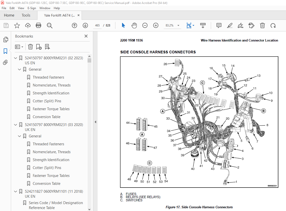
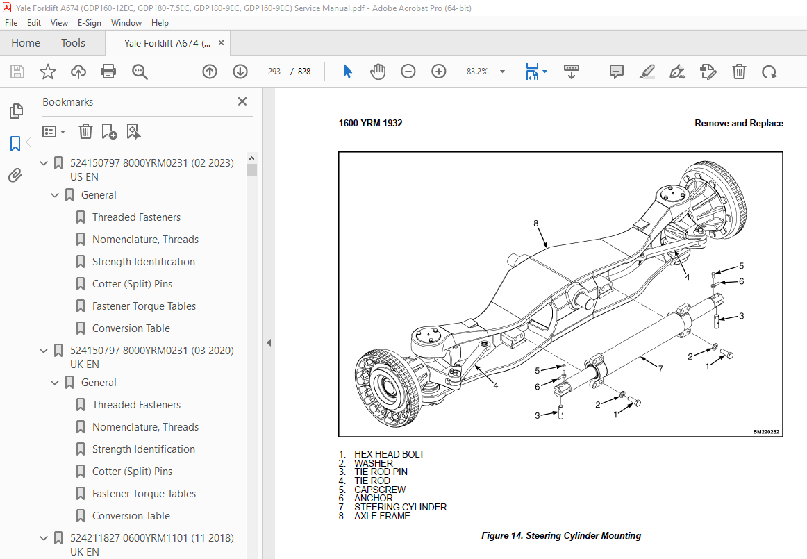
TABLE OF CONTENTS:
Yale Forklift A674 (GDP160-12EC, GDP180-7.5EC, GDP180-9EC, GDP160-9EC) Service Manual – PDF DOWNLOAD
524150797 8000YRM0231 (02 2023) US EN 1
General 7
Threaded Fasteners 7
Nomenclature, Threads 7
Strength Identification 8
Cotter (Split) Pins 9
Fastener Torque Tables 14
Conversion Table 16
524150797 8000YRM0231 (03 2020) UK EN 23
General 27
Threaded Fasteners 27
Nomenclature, Threads 27
Strength Identification 28
Cotter (Split) Pins 29
Fastener Torque Tables 34
Conversion Table 36
524211827 0600YRM1101 (11 2018) UK EN 43
Series Code / Model Designation Reference Table 47
General 47
Fault Codes 48
Normal Mode 48
Fault Log Mode 49
Access 49
Exit 49
Clear 49
Electronic Throttle Calibration 49
Electronic Throttle Calibration Procedure 50
Stationary Regeneration Procedure 50
550033400 0100YRM1390 (12 2018) UK EN 79
Series Code / Model Designation Reference Table 87
General 87
Description of Operation 89
Cab Structure 89
Cab Tilt System 89
Cab Tip-Up System 91
Tilting the Cab 92
Raising 92
Lowering 93
Remove and Install 94
Cab Door Assembly 94
Cab Door 94
Remove 94
Install 94
Door Hinge 95
Remove 95
Install 95
Door Latch 96
Remove 96
Install 96
Door Handle 96
Remove 96
Install 96
Door Release 97
Remove 97
Install 97
Door Push Button 97
Remove 97
Install 98
Cab Tilt System 98
Electric Tilt Pump 98
Remove 98
Install 98
Hand Tilt Pump 98
Remove 98
Install 99
Cab Tilt Cylinder 100
Remove 100
Disassemble 100
Clean 102
Inspect 102
Assemble 102
Install 103
Latch 103
Remove 103
Install 104
Brake and Inching Pedal 105
Remove 105
Install 105
Accelerator Pedal and Sensor 106
Remove 106
Install 106
Adjust Sensor 106
Seat Assembly 106
Seat 106
Remove 106
Install 107
Seat Cushion 107
Remove 107
Install 108
Back Cushion 108
Remove 108
Install 108
Seat Suspension Replacement 108
Boot Replacement 108
Power Assist Armrest 132
Release Cable 132
Remove 132
Install 132
Gas Spring 132
Remove 132
Install 133
Joystick 133
Remove 133
Install 133
Electrical Levers 133
Remove 133
Install 134
Armrest Rocker Switches 134
Remove 134
Install 134
Armrest Top Cover 134
Remove 134
Install 134
Instrument Panel 135
Key Switch 135
Remove 135
Install 135
12V Power Socket 135
Remove 135
Install 135
Electric-Operated Heat Control and Air Recirculation Control (Airco Only) 136
Remove 136
Install 136
Cable-Operated Heater Control (Heater Only) 137
Remove 137
Install 137
Air Conditioning Switch Replacement 137
Instrument Panel Rocker Switches Replacement 137
Parking Brake Switch 138
Remove 138
Install 138
Indicator Display Replacement 138
Instrument Panel Top Console 138
Remove 138
Install 139
Steering Wheel and Column Assembly 139
Steering Wheel and Horn 139
Remove 139
Install 141
Steering Column Assembly 141
Remove 141
Install 142
Adjustment Handle 142
Remove 142
Install 142
Main Warning Lights 143
Remove 143
Install 143
Shift Lever 143
Remove 143
Install 143
Turn Signal Lever 143
Remove 143
Install 143
Window Wipers 144
Window Wiper Assembly Replacement 144
Remove 144
Install 144
Window Wiper Motor Replacement 144
Front Window Wiper Motor 144
Install 144
Rear Window Wiper Motor Assembly 145
Remove 145
Install 145
Top Window Wiper Motor Assembly 145
Remove 145
Install 145
Window Washer System 146
Window Washer Reservoir and Pumps 146
Remove 146
Install 146
Window Washer Hoses 147
Hoses for Top and Rear Window 147
Install 148
Window Washer Spray Nozzles 148
Front Window 148
Remove 148
Install 148
Rear Window 149
Remove 149
Install 149
Top Window 149
Remove 149
Install 149
Window Replacement 149
Front Window 151
Remove 151
Install 151
Rear Window 151
Remove 151
Install 151
Top Window 152
Remove 152
Install 152
Door, Upper/Lower Window 153
Remove 153
Install 153
Sliding Window and Sliding Tracks 153
Remove 153
Install 155
Weather Strip Replacement 155
Window Stopper Replacement 155
Window Seal Replacement 156
Sliding Window Frame 156
Remove 156
Install 156
Floor Mat 156
Front Floor Mat 156
Remove 156
Install 157
Rear Floor Mat 157
Remove 157
Install 158
Radio Console 158
Remove 158
Install 158
Air Duct Replacement 159
Remove Front 159
Remove Rear 159
Install 160
Accessories 160
Mirror Replacement 160
Sunshade Replacement 160
Top 160
Rear 161
Map Light Replacement 161
Interior Fan Replacement 161
Training Seat 161
Field Installation 161
Remove 161
Label Replacement 162
Checks and Adjustments 162
Check Oil Level for Cab Tilt System 162
Door Striker Pin Adjustment 163
Brake Pedal Adjustment 163
Dry Brake 163
Wet Brake 164
Inching Pedal Adjustment 164
Inching Pedal Sensor Adjustment 164
Sensor Adjustment Using Dana Dashboard Software 164
Sensor Adjustment using the APC200 Display 165
Sensor Adjustment for Trucks with ZF Transmission 166
Inching Pedal Sensor Calibration 166
Sensor Calibration using Dana Dashboard Software 166
Sensor Calibration using APC200 Display 166
Sensor Calibration for Trucks with ZF Transmission 167
550035502 1300YRM1455 (11 2018) UK EN 171
Series Code / Model Designation Reference Table 175
General 175
Description 175
General 175
Clutch 180
Operation 180
Hydraulic Operation 180
Clutch Valve 181
Cooling and Lubrication 182
Control System 183
Transmission Control Unit (TCU) 184
Operating Modes 184
Normal Mode 184
Substitute Clutch Control 184
Limp-Home Mode 184
Transmission Shut Down Mode 184
TCU Shut Down Mode 184
Transmission Exceed Codes 184
Self-Test 185
Fault Codes 185
Description 185
Fault Log Mode 185
Access 185
Exit 186
Clear 186
Fault Log Memory 186
Fault Rectification 186
Hydraulic Control Valve 187
Hydraulic Control Valve Repair 188
Solenoid Replacement 188
Pressure Check 188
Pressure Specifications 189
Speed and Temperature Sensors 189
Speed Sensors 190
Test 191
Temperature Sensors 191
Shift Lever 191
PedalFoot Directional Control 191
ZF Transmission Test and Calibration 192
Transmission Test and Calibration 192
Precautions 192
Stall Test 192
Description 192
Stall Test Procedure 192
Inch Pedal Calibration 193
Description 193
Calibration 193
Brake and Inch Pedal Adjustment 193
Inch Sensor Adjustment 193
Inch Pedal Calibration 194
Preparation 194
Calibration Procedure Using the Calibration Switch 194
Calibration Procedure Using the Testman software 194
Inch Pedal Calibration Fault Codes 194
Clutch Calibration 195
Description 195
Clutch Calibration Procedure 196
Manual Clutch Calibration Procedure 196
Testman Clutch Calibration Procedure 197
Testman 197
Description 197
Connection 198
Truck Configuration 198
Configuration 198
Limitations 198
Capacities and Specifications 199
Electrical Specifications 199
Transmission Control Unit Diagram 199
ZF Transmission Fault Codes 201
Transmission Exceed Codes 201
Testman Fault Codes 202
550123390 0700YRM1929 (11 2018) UK EN 213
Series Code / Model Designation Reference Table 217
General 217
Cooling System 217
Cooling System Description 217
Cooling Cores 217
Fan 218
Fan Clutch 218
Fan Clutch Engagement 218
Shroud 219
Engine Cooling System 220
Water Pump 220
Thermostat 220
Expansion Tank And Radiator Cap 221
Cab Heater 221
Coolant 222
DEF Heater 223
Charge Air Cooling System 223
Transmission Oil Cooling System 223
Hydraulic Oil Cooling System 224
Hydraulic Oil Cooling 224
Oil Filtration and Oil Cooling 225
Brake Cooling 226
Hydraulic Control System 226
Service and Repair 226
Cooling System Checks 226
Basic Checks 226
Coolant Quality Checks 227
Coolant Flow Checks 227
Thermostat 227
Water Pump 228
Cooling Core Efficiency 228
Cooling Core Flow Restrictions 229
Engine Leak Tests 229
External Leak Test 229
Check for Coolant Leak Into The Engine Oil Sump 230
Combustion Leak Test 231
Engine Cooling System Maintenance 231
Draining the Engine Cooling System 231
Filling the Engine Cooling System 232
Flushing the Engine Cooling System 232
Cleaning the Engine Cooling System 233
Remove and Replace 233
Fan 233
Remove 233
Install 233
Drive Belt 234
Remove 234
Install 234
Belt Tensioner 235
Inspect 235
Remove 235
Install 235
Water Pump 235
Inspect 235
Remove 235
Install 236
Thermostat 236
Remove 236
Inspect 236
Install 237
Cooling Core Assembly 237
Remove 237
Cooling Cores 241
Disassembly 241
Assembly 241
Install 241
550123391 0900YRM1930 (11 2018) UK EN 247
General 251
Description and Operation 251
Remove and Replace 260
DEF Tank 260
Remove 260
Install 261
DEF Tank Fill Cap 261
DEF Tank Unit 261
Remove 261
Install 261
DEF Tank Suction Filter 262
Replace 262
DEF Pump Assembly 263
Remove 263
Install 263
DEF Pump Filter 263
Replace 263
DEF Dosing Valve 264
Remove 264
Checks and Adjustments 265
DEF Dosing Valve 265
DEF Pump 265
550123393 1600YRM1932 (11 2018) UK EN 269
General 273
Steering System Main Component Identification 273
Description and Operation 277
Steering System 277
Introduction 277
Description 277
Hydraulic Oil Flow Path 277
Priority Valve 277
Fundamentals 277
Description 277
Operation 277
Component Validation for Correct Operation 278
Steering Control Unit 278
Description 278
Steering Control Valve 278
Fundamentals 278
Operation 278
Component Validation for Correct Operation 279
Hand Pump 279
Fundamentals 279
Operation 279
Component Validation for Correct Operation 279
LS Relief Valve 279
Fundamental 279
Operation 279
Component Validation for Correct Operation 279
Shock Valve 279
Fundamental 279
Operation 279
Component Validation for Correct Operation 279
Steering Axle 279
Hydraulic Troubleshooting Flowcharts 280
Hydraulic Pressure Checks Preparation 280
Steering Relief Pressure Check 281
Pressure Check, Port MLS1 and MLS2 on the Main Control Valve 281
Steering Wheel Lock to Lock Check 282
Flowchart 283
Hydraulic Pressure Checks for Troubleshooting Flowcharts 283
Hydraulic Pressure Checks Preparation 284
Condition Check, Shuttle Valve L and M in the Main Control Valve 284
Condition Check, Logic Element N in the Main Control Valve 285
Condition Check, Priority Valve on the Main Control Valve 285
Remove and Replace 285
Steering Control Unit 285
Remove 285
Install 287
Wheels 288
Remove Wheels From Lift Truck 288
Install Wheels on Lift Truck 288
Steer Axle (G876/G877/A674) 289
Remove 289
Install 290
Tie Rod (G876/G877/A674) 292
Remove 292
Clean and Inspect 292
Install 292
Steering Cylinder (G876/G877/A674) 292
Remove 292
Clean and Inspect 294
Assemble and Install 296
Hubs (G876/G877/A674) 296
Remove and Disassemble 296
Clean and Inspect 296
Assemble and Install 296
Spindle (G876/G877/A674) 297
Remove 297
Clean 298
Assemble and Install 298
Steering Axle (A674) 298
Remove 298
Install 299
Tie Rod (A674) 300
Remove 300
Clean and Inspect 301
Install 301
Steering Cylinder (A674) 301
Remove 301
Clean and Inspect 304
Assemble and Install 304
Hubs (A674) 305
Remove and Disassemble 305
Clean and Inspect 306
Assemble and Install 306
Spindle 307
Remove 307
Clean and Inspect 308
Assemble and Install 308
Checks and Adjustments 308
Maximum Steering Angle Adjustment (G876/G877/A674) 308
Maximum Steering Angle Adjustment (A674) 309
Torque Specifications 309
Steering Control Unit 309
Steering Axle 309
Wheel Nuts 309
Steering Cylinder 309
550123394 1800YRM1933 (11 2018) UK EN 313
General 319
Brake System Main Component Identification 319
Description 322
Brake System 323
Service Brakes 323
Park Brake 323
Description 323
Hydraulic Oil Flow Path 323
Brake Accumulator Charging System 323
Service Brake System 323
Park Brake System 323
Priority Valve 324
Fundamentals 324
Description 324
Operation 324
Component Validation for Correct Operation 324
Brake Control Manifold 324
Description 324
Orifice (F) 325
Fundamentals 325
Description 325
Operation 325
Component Validation for Correct Operation 326
Unloading Valve 326
Fundamentals 326
Operation 326
Component Validation for Correct Operation 326
Screen 326
Description 326
Component Validation for Correct Operation 326
Check Valve 326
Description 326
Component Validation for Correct Operation 326
Pressure Reducer Valve 326
Fundamentals 326
Operation 326
Component Validation for Correct Operation 326
Park Brake Selector Valve 326
Fundamentals 326
Operation 326
Component Validation for Correct Operation 326
Brake Accumulator 326
Fundamentals 326
Operation 327
Component Validation for Correct Operation 327
Brake Treadle Valve 327
Fundamentals 327
Description 327
Operation 327
Brake Treadle Valve Repair 327
Remove 327
Install 328
Accumulator 328
Remove 328
Disassemble 329
Clean 332
Inspect 332
Repair 332
Assemble 332
Install 333
Pre-Charge Filling 333
Parking Brake 334
Parking Brake Caliper 334
Remove 334
Disassemble 336
Clean and Inspect 337
Assemble 337
Install 338
Parking Brake Caliper Pads 338
Remove 338
Install 338
Parking Brake Bleed 338
Parking Brake Emergency Release 339
Brake Flow Distribution Manifold 339
Remove 339
Pressure Relief Valve 341
Disassemble 341
Clean and Inspect 342
Assemble 342
Install 342
Brake Control Manifold 342
Remove 343
Orifices F and G 344
Disassemble 344
Assemble 344
Orifice H 344
Disassemble 344
Assemble 344
Unloading Valve (B) 344
Disassemble 344
Assemble 345
Screen 345
Disassemble 345
Assemble 345
Check Valve (E) 345
Disassemble 345
Assemble 345
Pressure Reducer Valve (C) 345
Disassemble 345
Assemble 346
Park Brake Selector Valve (A) 346
Disassemble 346
Assemble 346
Install 347
Gear Pump 347
Remove 347
Disassemble 347
Clean 348
Inspect 349
Assemble 349
Install 350
Hydraulic Troubleshooting Flowcharts 351
Mechanical Troubleshooting 354
Checks and Adjustments 355
Hydraulic Pressure Checks Preparation 355
Park Brake Selector Valve Check 356
Park Brake Selector Valve Coil Check 356
Accumulator Pre-Charge Check 356
Parking Brake Adjustment 357
Condition Check, Shuttle Valve L in the Main Control Valve 358
Condition Check, Shuttle Valve N in the Main Control Valve 358
Condition Check, Priority Valve on the Main Control Valve 359
Pressure Check, Port MLS1 359
Torque Specifications 359
Hydraulic Hose Torque Specifications 359
550123395 1900YRM1934 (04 2020) UK EN 363
Fundamentals 371
Basic Principles of Flow Control Systems 371
Orifice (Fixed/Variable) 371
Basic Principle 371
Pressure Compensated Flow Control Valve 372
Basic Principle 372
Pressure Compensated Flow Control Valve Functional Description 372
Priority Valve 373
Basic Principle 373
Priority Valve Functional Description 373
Load Sense (LS) 374
Basic Principle 374
Load Sense Functional Description 374
Example 1 375
Example 2 375
Basic Principles of Pressure Control Systems 375
Direct Acting Relief Valves 376
Basic Principle 376
Direct Acting Relief Valve Functional Description 376
Two-Stage Relief Valve (Pilot-Operated Relief Valve) 376
Basic Principle 376
Two-Stage Relief Valve (Pilot-Operated Relief Valve) Functional Description 377
Pilot-Operated Selector Valves 378
Fundamentals 378
Function Description 378
Pump Pressure Free Flow Side 378
Function Pressure Blocked Flow Side 378
Unloading Valve (Accumulator Charging Valve) 379
Basic Principle 379
Unloading Valve (Accumulator Charging Valve) Functional Description 379
Counterbalance Valve 380
Basic Principle 380
Counterbalance Valve Functional Description 380
Pressure Reducer Valve 381
Basic Principle 381
Pressure Reducer Valve Functional Description 381
Description and Operation 382
Component Location and Identification 382
Main Control Valve 385
Introduction 385
Flow Path 385
Main Manifold 385
Introduction 385
Priority Valve (A) 386
Fundamentals 386
Description 386
Operation 386
Component Functionality Test 386
Check Valve (I) 386
Function Description 386
Function Operation 386
Component Functionality Test 386
Pilot Supply Circuit 386
Function Description 386
Pilot Supply Valve (F) 386
Fundamentals 386
Function Description 386
Function Operation 387
Component Functionality Test 387
Lift Pressure Selector Valve (B) 387
Function Description 387
Function Operation 387
Component Functionality Test 387
Check Valve (K) 387
Function Description 387
Component Functionality Test 387
Check Valve (Q) 387
Function Description 387
Component Functionality Test 387
Screen (O) 387
Function Description 387
Component Functionality Test 387
Relief Valve 387
Function Description 387
Load Sense Relief Valve (H) 388
Fundamentals 388
Functional Operation 388
Component Functionality Test 388
Pressure Controller on Pump 388
Fundamentals 388
Functional Operation 388
Component Functionality Test 388
Full Flow Relief Valve (C) and (G) 388
Fundamentals 388
Functional Operation 388
Component Functionality Test 388
Shuttle Valve (L) and (M) 389
Function Description 389
Component Functionality Test 389
Logic Valve (N) 389
Function Description 389
Function Operation 389
Load Sense Selector Valve (D) 389
Function Description 389
Component Functionality Test 389
Directional Control Valve Section 389
Functional Operation (System Level) 389
Directional Control Valve 390
Fundamentals 390
Description 390
Functional Operation 390
Electrical Actuation Module (Solenoid End Cap) 391
Functional Operation 391
Component Functionality Test 391
Lift Function 391
Function Description 391
Pilot-Operated Check Valve 392
Fundamentals 392
Function Description 392
Function Operation 392
Emergency Lowering Valve (LH Lift Section ONLY) 392
Function Description 392
Lowering Control Valve 392
Fundamentals 392
Function Description 392
Tilt Function 392
Function Description 392
Impact Relief Valve 393
Fundamentals 393
Function Description 393
Counterbalance Valve 393
Fundamentals 393
Function Description 393
Auxiliary Function 393
Function Description 393
Variable Displacement Pump 394
Function Description 394
Basic Functional Operation 394
Pressure Control Valve 395
Fundamentals 395
Operation 395
Load Sense Pressure Regulator 395
Fundamentals 395
Functional Operation 395
Repair 395
Main Control Valve 395
Remove 395
Clean 399
Inspect 399
Assemble 399
Install 400
Priority Valve (A) 401
Remove 401
Clean 401
Inspect 402
Component Functionality Test 402
Install 402
Check Valve (K) 402
Remove 402
Clean 402
Inspect 402
Component Functionality Test 402
Install 402
Check Valve (I) 402
Remove 402
Clean 402
Inspect 403
Component Functionality Test 403
Install 403
Check Valve (Q) 403
Remove 403
Clean 403
Inspect 403
Component Functionality Test 403
Install 403
Screen Cartridge (O) 403
Disassemble 403
Component Functionality Test 403
Assemble 403
Shuttle Valves (L) and (M) 404
Remove 404
Clean 404
Inspect 404
Component Functionality Test 404
Install 404
Logic Valve (N) 405
Remove 405
Clean 405
Inspect 405
Component Functionality Test 405
Install 405
Full Flow Relief Valve (c) (Relief Spool) 405
Remove 405
Clean 405
Inspect 406
Assemble 406
Install 406
Pilot Supply Valve (F) 406
Remove 406
Clean 406
Inspect 406
Assemble 406
Component Functionality Test 406
Install 406
Load Sense (LS) Relief Valve (H) and Full Flow Relief Valve (G) 406
Remove 406
Clean 406
Inspect 407
Component Functionality Test 407
Install 407
Load Sense Relief Valve (H) Adjustment 407
Full Flow Relief Valve (G) Adjustment 407
Load Sense Selector Valve (D) 407
Remove 407
Clean 407
Inspect 408
Assemble 408
Install 408
Lift Pressure Selector Valve (B) 408
Remove 408
Clean 408
Inspect 408
Assemble 408
Install 408
Variable Displacement Pump (Primary and Secondary) 409
Remove 409
Clean 410
Inspect 410
Assemble 410
Install 410
Electrical Actuation Module 411
Remove 411
Clean 411
Inspect 411
Assemble 412
Install 412
Emergency Lowering Valve (Left Slice Only) 413
Remove 413
Clean 413
Inspect 413
Install 413
Load Sense and Pressure Controller Valve on Pump 413
Remove 413
Clean 414
Inspect 414
Assemble 414
Install 414
Adjustment of Pressure Controller on Pump 414
Adjustment of Load Sense Controller on the Secondary Variable Pump 415
Adjustment of Load Sense Controller on the Primary Variable Pump 416
Directional Control Valve 417
Remove 417
Clean 417
Inspect 417
Assemble 417
Install 417
Manual End Cap 417
Remove 418
Clean 418
Inspect 419
Assemble 419
Install 419
Troubleshooting 419
Lift, Tilt, and/or Aux function does not move when applied Steering is operating normal 419
The truck is not
capable to lift
rated load at expected
max lift
speed 420
Tilt function
shakes 420
It is not
possible to
lower the
mast with
ignition key
turned to
ON 420
Steer and
brake accumulator
charge
function
does not operate 420
The truck is
hydraulically
loaded
during engine
start
Accumulator
charge
and steering
is possible
during
XMSN calibration 421
Torque Specifications 421
Torque Specifications 421
550123397 2200YRM1936 (11 2018) UK EN 423
General 427
Electrical Schematic and System Description 427
Electrical Schematic 427
Schematic Location Number 430
Electrical Components 430
Electrical Wires 430
Wire Identification Number 430
Electrical Wire Colors 431
Wire Harnesses 432
Harness Interconnection 434
Electrical Connectors 434
Connector Types 434
Connector Identification 435
Connector Pin Numbers 435
Connector Description 435
Fuses 435
Relays 439
Flyback Diodes 441
CAN (Controller Area Network) 441
Troubleshooting 442
Instrument Panel 442
Instrument Panel Connectors 445
LCD Display 446
Hourmeter Mode 446
Fault Code Mode 446
Transmission Calibration 447
Fault Code Log Mode 447
Access 447
Clear 447
Exit 448
General Fault Finding 448
Preparation 448
Define the Problem Area 448
Identify Possible Causes of Malfunction 448
Determine the Most Probable Cause 448
Fuse Check 448
Wiring Check 448
Component Check 448
Repair and Test 448
Wire Harness Identification and Connector Location 449
Frame Harness Connectors 459
Mast ECH Harness Connectors 461
Top Cab Harness Connectors 462
Side Console Harness Connectors 464
Cab Underfloor Harness Connectors 467
Armrest Harness Connectors 469
ECM Harness Connectors (Tier 3/Stage IIIA) 470
EAS/ECM Harness Connectors (Tier 4F/Stage IV) 471
DEF Tank Harness Connectors 473
Powertrain Harness Connectors 473
Hoodspine Harness Tier 3/Stage IIIA Connectors 474
Hoodspine Harness Tier 4F/Stage IV Connectors 475
550185564 0100YRM2107 (12 2018) UK EN 479
Series Code / Model Designation Reference Table 483
Description and Operation 483
Heater System 483
General 483
Air Conditioning 484
General 484
Dryer 485
Compressor Lubrication 486
Control Systems, Sensors, and Switches 486
Climate Control 487
Description 487
Service Menu 487
Set Up 488
View 1 and View 2 488
Error List 489
Statistics 489
Exit 489
Temperature Sensors 489
Troubleshooting 490
Water Valve 490
Troubleshooting 490
Troubleshooting 493
Insufficient or no cooling 493
Preliminary Checks 493
Checking System Air Output 493
Check The Sight Glass for Bubbles 493
Remove and Replace 496
Standard Heater Assembly 496
Access 496
Remove 496
Install 497
Standard Heater Parts 498
Heater Core 498
Remove 498
Install 499
Blower 500
Remove 500
Install 501
Water Valve 501
Remove 501
Install 502
Push/Pull Cable 502
Water Valve Cable 502
Remove 502
Install 503
Heater/Air Conditioner Assembly 503
Remove 503
Install 504
Heater/Air Conditioner Parts 505
Vent Door 505
Remove 505
Install 506
Heater Core 506
Remove 506
Install 507
Evaporator Core 507
Remove 507
Install 509
Blower 509
Remove 509
Install 510
Thermostat 510
Remove 510
Install 511
Water Valve 512
Remove 512
Install 513
Filtration 513
Fresh Air Filter 513
Remove 513
Install 513
Recirculation Air Filter 513
Remove 513
Install 514
Air Conditioning Technical Detail 514
Maintenance Procedures and Required Equipment 515
Maintenance Procedures 515
Installing Manifold Gauges 515
Refrigerant Recovery 517
Refrigerant Leak Check 518
Evacuation and Dehydration 518
General 518
Preparation 518
Procedure For Evacuation and DehydratingSystem (Triple Evacuation) 518
Procedure For Evacuation and DehydratingSystem (One Time Evacuation) 518
Adding Refrigerant to a System 519
Checking Refrigerant Charge 519
Adding Full Charge 519
Adding Partial Charge 519
Filter Drier 520
550205244 0100YRM1978 (11 2018) UK EN 525
Series Code / Model Designation Reference Table 529
General 529
Description 529
Remove and Install 530
Air Filter Assembly (Tier 3/Stage IIIA) 531
Remove 531
Install 531
Air Filter Assembly (Tier 4F/Stage IV) 532
Remove 532
Install 532
Exhaust System (Tier 3/Stage IIIA) 533
Remove 533
Install 534
Exhaust System (Tier 4F/Stage IV) 534
Exhaust Pipes High Mount 534
Remove 534
Install 534
Exhaust Pipes and Diffuser Low Mount 535
Remove 535
Install 536
Engine After Treatment (EAS) System (Tier4F\Stage IV) 536
Preparation 536
Remove 536
Install 538
Exhaust Seal Rings 538
Selective Catalytic Reducer (SCR) 539
Remove 539
Install 539
Decomposition Reactor Tube (DRT) 539
Remove 539
Install 540
Diesel Oxidation Catalyst (DOC) 540
Remove 540
Install 540
Hood Assembly 540
Remove 540
Install 541
Running Boards, Steps and Mud Flaps 542
Hydraulic Tank 543
Remove 543
Inspect 546
Clean 546
Steam Cleaning Method 546
Chemical Solution Cleaning Method 547
Repair 547
Small Leaks 547
Large Leaks 547
Inspection after Repair 547
Install 547
Fuel Tank 549
Remove 549
Clean and Repair 551
Install 551
Engine and Transmission (Tier 3/Stage IIIA) 552
Remove 552
Precautions 552
Remove Air Conditioning Compressor 552
Drain the Engine Cooling System 553
Drain Hydraulic Oil 553
Drain Transmission Oil 554
Disconnect Drive Shaft, Fan Clutch, Tubes, Pipes, Cables, Wires and Lines 554
Remove Engine and Transmission 556
Install 558
Install Engine and Transmission 558
Install Air Conditioning Compressor 559
Connect Drive Shaft, Fan, Tubes, Pipes, Cables, Wires and Lines 559
Refill the Systems 559
Starting the Engine 560
Engine and Transmission (Tier 4F/Stage IV) 560
Remove 560
Precautions 560
Remove Air Conditioning Compressor 561
Drain the Engine Cooling System 561
Drain Hydraulic Oil 562
Drain Transmission Oil 562
Disconnect Drive Shaft, Fan Clutch, Tubes, Pipes, Cables, Wires and Lines 562
Remove Engine and Transmission 565
Install 567
Install Engine and Transmission 567
Install Air Conditioning Compressor 567
Connect Drive Shaft, Fan, Tubes, Pipes, Cables, Wires and Lines 567
Refill the Systems 568
Starting the Engine 568
Operator’s Cab 569
Remove 569
Install 571
Cab Tilt System Oil Filling 572
Counterweight 573
Remove 573
Install 574
Label Replacement 575
Capacities and Specifications 575
Torque Values for Frame and Main Components 576
550205245 1400YRM1667 (11 2018) UK EN 581
General 585
How to Put Lift Truck on Blocks 585
Description And Operation 586
Drive Shaft 586
Differential 586
Planetary Gear Assembly 588
Drive Shaft Repair 590
Remove 590
Disassemble 591
Clean and Inspect 592
Assemble 592
Install 592
Oil Drain and Refill Procedures 592
Differential 592
Drain 592
Fill 593
Hub Assembly 593
Drain 593
Fill 593
Wet Brake Disk 594
Drain 594
Filling and de-aerating the service brakes 594
Drive Axle Removal 594
Planetary Housing Repair 596
Remove 596
Clean, Inspect, and Repair 603
Repairing and Replacing Parts 603
Welding 604
Clean 604
Ground or Polished Parts 604
Parts With Rough Finishes 604
Axle Assemblies 604
Drying Cleaned Parts 604
Preventing Corrosion 604
Inspect 605
Assemble 605
Wet Disc Brake Repair 612
Remove 612
Brake Housing 613
Disassemble 615
Brake Housing 615
Brake Carrier and Piston 616
Clean 617
Ground and Polished Parts 617
Parts With Rough Finish 618
Wet Disc Brake and Axle Assembly 618
Inspect 618
Face Seals 618
Disc 618
Wear Limits 619
Replace 619
Parts 619
Assemble 620
Brake Carrier and Piston 620
Install 622
Differential Repair 625
Remove 625
Differential Carrier From Axle Housing 625
Main Differential and Ring Gear Assembly From Differential Carrier 628
Drive Pinion and Pinion Carrier From Differential Carrier 630
Disassemble 633
Main Differential and Ring Gear Assembly 633
Drive Pinion, Bearings, and Pinion Carrier 634
Clean and Inspect 637
Assemble 637
Drive Pinion, Bearings, and Pinion Carrier 637
Pinion Bearings Preload Adjustment 640
Press Method 640
Flange Method 641
Triple-Lip Oil Seal 642
Pinion Carrier Shim Set Thickness Adjustment (Depth of Pinion) 643
Main Differential and Ring Gear Assembly 645
Differential Gears Rotating Torque 647
Install 648
Differential and Ring Gear Assembly 648
Differential Bearings Preload Adjustment 650
Method 1 650
Method 2 651
Ring Gear Runout Check 652
Ring Gear Backlash Adjustment 652
Tooth Contact Pattern Check 654
Thrust Screw Installation and Adjustment 656
Differential Carrier Into Axle Housing 657
Torque Specifications 659
550205248 8000YRM1663 (11 2018) UK EN 663
General 667
Weight and Dimensions 667
Loading Procedures 671
Loading A Truck on a Transport 671
Loading Disassembled Components 671
Unloading Procedures 672
Unloading A Truck From Transport 672
Lifting a Truck 672
Driving a Truck Off a Trailer 673
Unloading Disassembled Components 673
Moving and Towing 673
Moving a Disabled Lift Truck 673
Precautions 673
Towing A Lift Truck 674
Safety Procedures When Working Near The Mast 674
When Working Near The Mast Always 675
Before Starting Repairs To The Hydraulic System Always 675
Truck Assembly 676
Safety procedures When Working Near the Mast 676
Mast Installation 677
Preparations 677
Installing the Mast 677
Installing the Tilt Cylinders 678
Adjusting the Tilt Cylinders 679
Connecting the Lift Cylinders 679
Connecting the Mast Supply Hoses 680
Carriage and Forks 681
Installing the Carriage 681
Connecting the Header Hoses to the Carriage 681
Install the Forks 682
Installing Pin-Type Forks 682
Installing Quick Disconnect DFSSFP Forks 684
Installing Integrated DFSSFP Forks 684
Adjusting the Carriage 685
Adjusting Header Hose Tension 686
Adjusting the Electrical Cable Tension 686
Installing the Cab Lights 686
Lubrication Points 687
General Checks After Assembly 687
Plumbing Check 688
Lubrication Check 688
Fluid Level Check 688
Functionality Check 688
Literature Package Check 688
Cleaning 688
Labels 688
Wheels and Tires 688
Remove Wheels From Lift Truck 688
Adding Air Pressure to Tires 694
Install Wheels on Lift Truck 695
Capacities and Specifications 695
Torque Values 695
Pre-Delivery 695
Adjust Timing For Automatic Engine Shut Down 696
Perform Pre-Delivery Inspection 696
Delivery 697
Instructions Operating Manual 697
Instructions Daily Maintenance 697
Handing Over Truck 697
550205249 8000YRM1981 (11 2018) UK EN 701
Counterweight Weights 705
Lift Truck Weights 705
Capacities 705
Electrical System 706
Engine Specifications 706
Mast Speeds 707
Tire Sizes 707
Hydraulic System 707
Torque Specifications, General 708
Transmission ZF 708
Counterweight 708
Steering 708
Wheel Nuts 708
Hydraulic System 708
Mast 709
Carriage 709
Tilt Cylinders 709
Torque Specifications, Cummins Diesel 709
Lubrication System 709
550205250 8000YRM1982 (01 2020) UK EN 713
Electrical Schematic 8-18 Ton T3/T4 Final 717
Hydraulic Schematic 744
550205251 8000YRM1983 (07 2019) UK EN 751
General 757
Serial Number Data 757
Truck Handling Procedures 758
Moving and Towing a Lift Truck 758
Precautions 758
Moving the Truck 758
Putting a Lift Truck on Blocks 759
Raising the Drive Tires 759
Raising the Steering Tires 759
Cleaning a Lift Truck 760
Safety Procedures Before Starting Maintenance 761
Making Checks with Engine Running 761
Fire Hazard 761
Hydraulic Service Switch 762
Transmission Calibration Switch 762
Wait 100 Seconds Before Disconnecting Battery 762
Periodic Maintenance Schedule 762
Daily Inspection 763
Daily Condition Checks 763
Daily Fluid Level Checks 764
Daily Checks with Engine Running 765
Initial Inspection 766
First Inspection after First 20 Hours of Operation 766
First Inspection after First 40 Hours of Operation 766
First Inspection after First 100 Hours of Operation 766
First Inspection after First 250 Hours of Operation 767
Periodic Maintenance 767
Inspect and Adjust 767
Lubricate 770
Change 771
Periodic Maintenance Procedures 772
Air Conditioning System 772
Brake System Accumulator 773
Cab Air Filter 773
Cab Door Hinges 773
Control Levers, Switches, and Pedals 773
Cooling System 774
Coolant Hoses 774
Coolant Level 774
Coolant Quality 774
Cooling Fan 774
Cooling Fan Belt 775
Cooling Fan Belt Tensioner and Pulleys 775
Bearing Condition 775
Pulley Alignment 775
Tensioner Condition 775
Crankcase Breather Element (Tier 4F/Stage IV Only) 776
Diesel Exhaust Fluid (DEF) System 778
DEF Pump Filter 778
DEF Tank Fill Cap 779
DEF Tank Suction Filter 779
Drive Axle and Differential 780
Check Oil level 780
Change Oil 780
Check Wheel Bearing Pre-Load 781
Drive Shaft 783
Engine Air Filter 784
Engine Air Intake Piping and Charge Air Piping 784
Engine and Transmission Mounts 785
Engine Compartment 785
Engine Oil 786
Engine Oil Level 786
Engine Oil and Engine Oil Filter 786
Engine Valve Adjustment 787
Fault Codes 789
Forks 789
Fork Guide Bearing Blocks 790
Fork Pins, Carriage Pins, and Carriage Sliding Surfaces 791
Frame, Mast, Carriage and Attachment 791
Fuel, Oil, DEF or Coolant Leaks 791
Fuel/Water Separator and Final Fuel Filter 792
Fuel Tank Breather 792
Header Hose Assembly 793
Horn, Gauges, Lights, Alarms and Control System 793
Hydraulic Brake Cooling Filter 793
Remove 793
Replace 793
Hydraulic System Oil 794
Hydraulic Oil Testing Procedures 794
Hydraulic Oil Replacement 795
Hydraulic Tank Breather 796
Hydraulic Tank Return Filter 797
Inching Pedal Sensor Calibration 797
Lift Chains 797
Check and Lubricate Lift Chains 797
Adjust Lift Chains 797
Inspect Lift Chains 799
Chain Elongation 799
Lift Chain Wear and Damage 800
Lift System Accumulator (Optional) 800
Load Rollers 800
Carriage Load Rollers 800
Inner Mast Load Rollers 800
Mast, Carriage and Attachment 801
Mast Pivot Pins 801
Operator Presence System 801
Operator Restraint System 802
Seat Belt and Seat Rails 802
Steering Column Latch 802
Parking and Service Brakes 802
Radiator Assembly 803
Steering Axle Grease Fittings 803
King Pins 803
Tie Rod Pins 803
Steering System 803
Steering Wheel Hub Bearings 803
Remove and Disassemble 803
Clean and Inspect 805
Assemble and Install 805
Tilt Cylinder Pivot Pins 806
Transmission 807
Transmission Clutch Calibration 807
Transmission Oil Level 807
Transmission Oil Filter 807
Vibration Damper 808
Warning and Safety Labels 809
Windows and Mirrors 809
Windshield Washer Fluid 809
Wheels and Tires 810
Wheels, Tires, and Tire Pressure 810
Remove Wheels from Lift Truck 811
Adding Air Pressure to Pneumatic Tires 816
Install Wheels on Lift Truck 817
Capacities and Specifications 818
Approved Fuel and Engine Oil 818
Approved Oils, Fluids, and Grease 818
Engine Oil Viscosity 819
Lift Chain Lubricant Requirements 819
Fuses and Relays 820
More products