$43.95
Yale Forklift A7S1 (GP GLP GDP040 20UX) Service Manual – PDF DOWNLOAD
Yale Forklift A7S1 (GP GLP GDP040 20UX) Service Manual – PDF DOWNLOAD
FILE DETAILS:
Yale Forklift A7S1 (GP GLP GDP040 20UX) Service Manual – PDF DOWNLOAD
Language : English
Pages : 2320
Downloadable : Yes
File Type : PDF
PART NO. 550108890
IMAGES PREVIEW OF THE MANUAL:
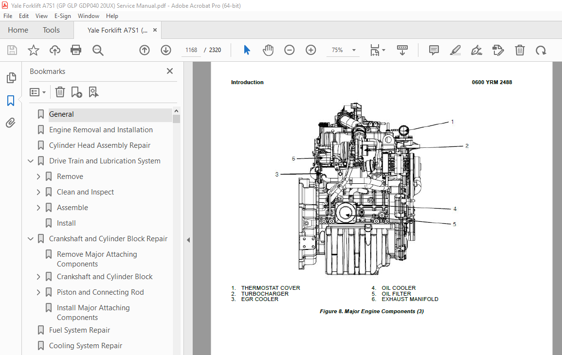
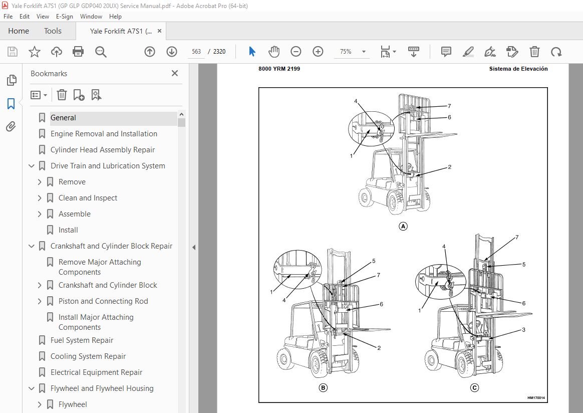
TABLE OF CONTENTS:
Yale Forklift A7S1 (GP GLP GDP040 20UX) Service Manual – PDF DOWNLOAD
General 9
Engine Removal and Installation 13
Cylinder Head Assembly Repair 14
Drive Train and Lubrication System 55
Remove 55
Disassemble 55
Oil Pan 55
Oil Pump (Front Cover) 58
Clean and Inspect 59
Front Case 59
Oil Seal 59
Counterbalance Shaft 59
Oil Pump 59
Assemble 60
Counterbalance Shaft Bearings 60
Oil Pump (Front Cover) 61
Oil Pan 63
Install 63
Crankshaft and Cylinder Block Repair 65
Remove Major Attaching Components 65
Crankshaft and Cylinder Block 65
Remove 65
Clean and Inspect 66
Boring Cylinder 67
Install 68
Piston and Connecting Rod 70
Remove 70
Disassemble 71
Clean and Inspect 71
Assemble 72
Install 74
Piston 74
Rod Bearing 75
Install Major Attaching Components 76
Fuel System Repair 77
Cooling System Repair 78
Electrical Equipment Repair 79
Flywheel and Flywheel Housing 80
Flywheel 80
Remove 80
Install 81
Flywheel Housing 81
Remove 81
Install 81
POWER TAKE OFF (PTO), REMOVE AND INSTALL 82
REMOVE COVER 82
INSTALL COVER 82
Engine Specifications 84
Engine Data 84
Engine Tuning 85
Cylinder Head 86
Intake/Exhaust Valve and Guide 86
Valve Spring 86
Gear Train and Camshaft 87
Camshaft 87
Idle Gear Shaft and Bushing 87
Cylinder Block 87
Crankshaft 87
Piston 87
Piston Ring 88
Connecting Rod 88
Oil Pump 88
Engine Oil Pressure 88
Drive Gear Clearance 88
Driven Gear Clearance 88
Torque Specifications 89
Special Tools 91
General 103
Engine Identification 103
Major Engine Component Identification 103
Location of Labels 103
Engine Removal and Installation 104
Cylinder Head Assembly Repair 105
Valve Covers and Fuel Injectors 105
Remove 105
Clean and Inspect 108
Install 109
Rocker Arm Assembly 109
Remove 109
Disassemble 110
Clean and Inspect 111
Push Rods 111
Rocker Arm Assembly 111
Assemble 111
Install 112
Valve Clearance Adjustments 112
Compression Test 113
Cylinder Head Assembly 113
Remove 113
Disassemble 123
Valves and Valve Springs, Remove 123
Valve Guides, Remove 124
Clean and Inspect 124
Cylinder Head 125
Valve Guides 125
Valves 125
Valve Sink 126
Valve Seat 126
Valve Springs 127
Assemble 127
Valve Guides, Install 127
Valves and Valve Springs, Install 128
Install 129
Timing Gear Case and Timing Gears Repair 133
Timing Gear Case Cover 133
Remove 133
Clean and Inspect 134
Install 134
Timing Gears 135
Oil Pump Driven Gear 135
Remove 135
Install 135
Crankshaft Gear 135
Remove 135
Install 136
Idler Gear 136
Remove 136
Inspect 136
Install 137
Camshaft Gear 137
Remove 137
Install 137
Drive Train, Camshaft, and Cylinder Block Repair 138
Remove 138
Disassemble 138
Pistons and Connecting Rods 138
Crankshaft 139
Camshaft 141
Remove 141
Install 141
Clean and Inspect 141
Cylinder Block 142
Honing and Boring 142
Cylinder Correction (Oversize) 143
Pistons 144
Piston Ring Gap 144
Piston Ring Groove 144
Connecting Rod and Piston Pin 145
Crankshaft 147
Camshaft 148
Assemble 149
Camshaft 149
Crankshaft 149
Pistons and Connecting Rods 150
Install 151
Lubrication System Repair 152
Engine Oil and Oil Filter Change 152
Oil Pan 152
Remove 152
Install 153
Oil Suction Tube 153
Remove 153
Clean 153
Install 153
Oil Pump 153
Remove 153
Clean and Inspect 154
Outer Rotor Outside Clearance 154
Outer Rotor to Inner Rotor Tip Clearance 154
Rotor Cover Clearance 155
Install 155
Fuel System Repair 156
Fuel Injectors 156
Remove 156
Inspect 156
Clean 156
Replace 156
Install 156
Test 156
Fuel Injection Pump/Supply Pump 157
Remove 157
Clean and Inspect 159
Install 159
Cooling System Repair 161
Accessory Drive Belt 161
Remove 161
Inspect 161
Install 162
Accessory Drive Belt, Adjustment 162
Water Pump 162
Remove 162
Install 164
Thermostat 164
Remove 164
Inspect 165
Install 165
Flywheel and Flywheel Housing 167
Flywheel 167
Remove 167
Install 167
Flywheel Housing 167
Remove 167
Install 167
Electrical Equipment Repair 168
Alternator 168
Remove 168
Install 168
Starter 169
Remove 169
Install 169
Engine Specifications 170
Engine Data 170
Engine Tuning 171
Cylinder Head 171
Intake/Exhaust Valve and Guide 171
Valve Spring 172
Rocker Arm and Shaft 172
Push Rod 172
Gear Train and Camshaft 172
Camshaft 172
Idle Gear Shaft and Bushing 172
Backlash of Each Gear 173
Cylinder Block 173
Crankshaft 173
Piston 173
Piston Ring 174
Connecting Rod 174
Rod Small End 174
Tappet 174
Oil Pump 175
Engine Oil Pressure 175
Outer Rotor Outside Clearance 175
Outer Rotor Side Clearance 175
Inner Rotor to Cover 175
Standard Torque Specifications 176
Standard Torque Chart 176
Special Torque Specifications 177
Special Tools 178
Forklift Truck Main Parts 191
Description of Forklift Truck Main Parts 191
Forklift Main Technical Parameters 192
Main Technical Parameters 192
Power System 195
Engine System 195
Engine Overview 195
Fuel System 196
Fuel Tank 197
Fuel Level Sensor 198
Maintenance of Fuel System 199
Fuel filter service 199
Hydraulic Transmission Case and Torque Converter 200
Overview 200
Torque Converter 201
Hydraulic Clutch 202
Control Valve, Safety Valve, and Inching Valve 203
Transmission Case 205
Transmission Pump 205
Transmission hydraulic schematic 205
Speed Reducer and Speed Differential 206
Speed Reducer 206
Speed Differential 207
Towing the Lift Truck 207
Oil Inlet/Outlet Connection Location 207
Drive Axle 208
Overview 208
Maintenance of Drive Axle 209
Steering System 210
Steering System 210
Overview 210
Hydraulic Steering Gear Assembly 210
Steering Cylinder 211
Inspection of Reassembled Steering System 212
Troubleshoot Steering System 213
Steering and Drive Axle Information 214
Steering Axle 214
Overview 214
Steering Knuckle and Steering King Pin 215
Steering Wheel Bearing Pre-load Information 216
Brake System 216
Overview 217
Brake Master Cylinder 217
Wheel Brake 217
Automatic Brake Adjuster 221
Manual Brake 222
Adjustment of Brake Pedal 222
Maintenance 222
Examination of Wheel Brake 225
Assemble, Wheel Brake 226
Operating Test Automatic Clearance Regulator 228
Troubleshoot Wheel Brake 229
Hydraulic System 231
Overview 231
Steering Control Unit 232
Multi-way Valve and Priority spool 232
Operation of Spool Valve 232
Neutral Position 232
Spool Valve (Pushed In): 233
Spool Valve (Pulled out): 233
Primary Relief Valve and Priority Spool 233
Inclined Auto-Lock Valve 234
Hydraulic System Main Oil Circuit 235
Lift Cylinder 237
Velocity Fuse 239
Tilt Cylinder 240
Maintenance of Hydraulic Pump 241
Disassemble, Main Oil Pump 241
Inspection and Repair 241
Assemble, Main Oil Pump 244
Test 245
Troubleshoot Hydraulic System 249
Lifting System 250
Safety Procedures When Working Near Mast 250
Overview 252
Inside and Outside Masts 252
Carriage 253
Adjustment of Lifting System 253
Electrical System 254
Overview 254
Power supply system 254
Starting system 254
Ignition system (ICE forklift truck) 254
Preheating system (diesel forklift truck) 254
Dash Instrument Display System 255
Lighting, sound and alarm system 255
Electrical Box 255
Battery 255
Description and Summary of Basic Truck Operations 255
Introduction to the Power Distribution Module (PDM) 257
Electrical Schematics 257
Troubleshoot Electrical System 271
Troubleshooting 271
Drive, Operation, and Routine Maintenance of Forklift Truck 272
Cooling System Troubleshooting and Service 272
Coolant level check 272
Flushing the cooling system 272
Adding antifreeze/coolant 272
Cleaning the radiator 272
Oils Used for Forklift Truck 273
Hydraulic Oil Gauge and Hydraulic Oil fill 273
General inspection requirements 273
Fill Level Requirements 273
Lubrication System 273
PDM Schematics 275
Principaux éléments du chariot élévateur 291
Description des principaux éléments du chariot élévateur 291
Principales caractéristiques techniques du chariot élévateur 292
Principales caractéristiques techniques 292
Système de traction 295
Circuit moteur 295
Vue d’ensemble des moteurs 295
Système de carburant 296
Réservoir de carburant 297
Capteur du niveau de carburant 298
Maintenance du circuit de carburant 299
Entretien du filtre à carburant 299
Carter de transmission hydraulique et convertisseur de couple 299
Vue d’ensemble 300
Convertisseur de couple 301
Embrayage hydraulique 302
Distributeur, clapet de sécurité et clapet de marche lente 303
Carter de transmission 305
Pompe de transmission 305
Schéma hydraulique de transmission 305
Réducteur de vitesse et différentiel 307
Réducteur de vitesse 307
Différentiel de vitesse 307
Remorquage du chariot élévateur 308
Emplacement des raccords d’entrée/sortie d’huile 308
Pont moteur 308
Vue d’ensemble 309
Maintenance du pont moteur 309
Système de direction 310
Système de direction 310
Vue d’ensemble 310
Ensemble boîtier de direction hydraulique 310
Vérin de direction 311
Contrôle du système de direction remonté 312
Dépannage du système de direction 312
Essieu directeur et pont moteur 313
Essieu directeur 313
Vue d’ensemble 314
Porte-fusée de direction et pivot central de direction 316
Précharge du roulement de roue directrice 316
Circuit de freins 316
Vue d’ensemble 317
Maître-cylindre de frein 317
Frein de roue 318
Système de réglage automatique de frein 322
Frein manuel 323
Réglage de la pédale de frein 323
Maintenance 324
Contrôle du frein de roue 326
Montage du frein de roue 327
Test de fonctionnement du système de réglage automatique du jeu 329
Dépannage du frein de roue 330
Circuit hydraulique 332
Vue d’ensemble 332
Boîtier de direction 333
Distributeur multivoie et tiroir prioritaire 333
Fonctionnement du clapet à tiroir 333
Position neutre 334
Clapet à tiroir (enfoncé) : 334
Clapet à tiroir (tiré) : 334
Clapet de décharge principal et tiroir prioritaire 335
Clapet de verrouillage automatique de l’inclinaison 336
Circuit d’huile principal du système hydraulique 337
Vérin de levage 339
Limiteur de débit 341
Vérin d’inclinaison 342
Maintenance de la pompe hydraulique 343
Démontage de la pompe à huile principale 343
Contrôle et réparation 343
Montage de la pompe à huile principale 346
Test 347
Dépannage du circuit hydraulique 351
Système de levage 352
Mesures de sécurité lors du travail à proximité du mât 352
Vue d’ensemble 355
Mâts intérieur et extérieur 356
Tablier 356
Réglage du système de levage 356
Circuit électrique 358
Vue d’ensemble 358
Système d’alimentation 358
Système de démarrage 358
Système d’allumage (chariot élévateur à moteur thermique) 358
Système de préchauffage (chariot élévateur diesel) 358
Système d’afficheur tableau de bord 358
Système d’éclairage, de son et d’alarme 358
Boîtier électrique 359
Batterie 359
Description et synthèse du fonctionnement de base du chariot 359
Présentation du module de distribution électrique 360
Schémas électriques 361
Procédez au diagnostic du circuit électrique 375
Détection des pannes 376
Conduite, utilisation et maintenance courante du chariot élévateur 376
Dépannage et entretien du circuit de refroidissement 376
Contrôle du niveau de liquide de refroidissement 376
Rinçage du circuit de refroidissement 377
Ajout d’antigel/liquide de refroidissement 377
Nettoyage du radiateur 377
Huiles utilisées sur les chariots élévateurs 377
Jauge d’huile hydraulique et remplissage de l’huile hydraulique 377
Exigences de contrôle général 377
Exigences de niveau de remplissage 377
Système de lubrification 378
Schéma de principe du module de distribution électrique 380
Hauptkomponenten des Gabelstaplers 395
Beschreibung der Hauptkomponenten des Gabelstaplers 395
Technische Hauptparameter des Gabelstaplers 396
Technische Hauptparameter 396
Antriebssystem 399
Motorsystem 399
Überblick über den Motor 399
Kraftstoffsystem 400
Kraftstofftank 401
Kraftstoffstandsensor 402
Wartung des Kraftstoffsystems 403
Wartung des Kraftstofffilters 403
Hydraulikgetriebegehäuse und Drehmomentwandler 403
Überblick 404
Drehmomentwandler 405
Hydraulikkupplung 406
Regelventil, Überdruckventil und Kriechgangventil 407
Getriebegehäuse 409
Getriebepumpe 409
Schaltplan Getriebehydraulik 409
Drehzahlminderer und Differenzial 411
Drehzahlminderer 411
Differenzial 411
Abschleppen des Staplers 411
Lage des Öleinlass-/-auslassstutzens 411
Antriebsachse 412
Überblick 412
Wartung der Antriebsachse 413
Lenksystem 413
Lenksystem 413
Überblick 414
Baugruppe hydraulisches Lenkgetriebe 414
Lenkzylinder 415
Überprüfung des wieder zusammengebauten Lenksystems 416
Fehlerbehebung beim Lenksystem 416
Angaben zur Lenk- und Antriebsachse 417
Lenkachse 417
Überblick 418
Achsschenkel und Lenkkönigszapfen 419
Angaben zur Lagervorspannung am Lenkrad 420
Bremssystem 420
Überblick 421
Hauptbremszylinder 421
Radbremse 422
Automatischer Bremseinsteller 426
Manuelle Bremse 427
Einstellen des Bremspedals 427
Wartung 428
Überprüfung der Radbremse 430
Zusammenbauen der Radbremse 431
Betriebstest automatischer Abstandseinsteller 433
Fehlerbehebung bei der Radbremse 434
Hydrauliksystem 435
Überblick 436
SCU 437
Mehrwegeventil und Vorrangschieber 437
Funktionsweise des Schieberventils 437
Neutralstellung 438
Schieberventil (verschlossen): 438
Schieberventil (geöffnet): 438
Primärüberdruckventil und Vorrangschieber 439
Neigeselbstsperrventil 440
Hauptölkreislauf des Hydrauliksystems 441
Hubzylinder 443
Hydrauliksicherung 445
Neigezylinder 446
Wartung der Hydraulikpumpe 447
Zerlegen der Hauptölpumpe 447
Überprüfung und Reparatur 447
Zusammenbauen der Hauptölpumpe 450
Test 451
Fehlerbehebung beim Hydrauliksystem 455
Hubsystem 456
Sicherheitsvorkehrungen bei Arbeiten in der Nähe des Hubgerüsts 456
Überblick 459
Inneres und äußeres Hubgerüst 460
Gabelträger 460
Einstellen des Hubsystems 460
Elektrisches System 462
Überblick 462
Stromversorgung 462
Startsystem 462
Zündsystem (Gabelstapler mit Verbrennungsmotor) 462
Vorglühanlage (Gabelstapler mit Dieselmotoren) 462
Instrumentenanzeigesystem 462
System für Beleuchtung, Akustik und Warnmeldungen 462
Elektrokasten 463
Batterie 463
Beschreibung und Zusammenfassung der wichtigsten Staplerfunktionen 463
Einführung in das PDM 465
Schaltpläne 465
Fehlersuche im elektrischen System 479
Fehlersuche 479
Fahren, Betrieb und regelmäßige Wartung des Gabelstaplers 480
Kühlsystem – Fehlersuche und Wartung 480
Prüfung Kühlmittelstand 480
Spülen des Kühlsystems 480
Nachfüllen von Frostschutzmittel/Kühlmittel 481
Reinigen des Kühlers 481
Für Gabelstapler verwendete Öle 481
Hydraulikölfüllstandsanzeige und Nachfüllen von Hydrauliköl 481
Allgemeine Überprüfung 481
Vorgaben für den Füllstand 481
Schmiersystem 482
PDM-Schaltplan 484
Partes Principales de la Carretilla Elevadora 499
Descripción de las Partes Principales de la Carretilla Elevadora 499
Parámetros Técnicos Principales de la Carretilla Elevadora 500
Parámetros Técnicos Principales 500
Sistema de Propulsión 503
Sistema del Motor 503
Visión General del Motor 503
Sistema de combustible 504
Depósito de combustible 504
Sensor de nivel de combustible 506
Mantenimiento del Sistema de Combustible 507
Intervención de servicio del filtro de combustible 507
Caja de la Transmisión Hidráulica y Convertidor de Par 507
Visión General 508
Convertidor de par 509
Embrague Hidráulico 510
Válvula de Control, Válvula de Seguridad y Válvula de Marcha Lenta 511
Caja de transmisión 513
Bomba de la Transmisión 513
Esquema hidráulico de la transmisión 513
Reductor de Velocidad y Diferencial de Velocidad 515
Reductor de velocidad 515
Diferencial de Velocidad 515
Remolcado de la carretilla elevadora 516
Ubicación de la Conexión de Entrada/Salida de Aceite 516
Árbol propulsor 516
Visión General 517
Mantenimiento del Árbol Propulsor 517
Sistema de dirección 518
Sistema de dirección 518
Visión General 518
Conjunto de Engranaje de Dirección Hidráulica 518
Cilindro de dirección 520
Inspección del Sistema de Dirección una vez Rearmado 521
Efectúe la Localización de Averías en el Sistema de Dirección 521
Información de la Dirección y del Árbol Propulsor 522
Eje de dirección 522
Visión General 523
Rótula de la Dirección y Pasador Principal de la Dirección 525
Información de Precarga del Cojinete de la Rueda de Dirección 525
Sistema de freno 525
Visión General 526
Cilindro maestro del freno 526
Freno de la Rueda 527
Ajustador Automático del Freno 531
Freno Manual 532
Ajuste del Pedal del Freno 532
Mantenimiento 533
Examen del Freno de la Rueda 535
Montaje, Freno de la Rueda 536
Prueba de Funcionamiento del Regulador de Holgura Automático 538
Efectúe el procedimiento de Localización de Averías del Freno de la Rueda 539
Sistema hidráulico 540
Visión General 541
Unidad de control de dirección 542
Válvula Múltiple y Carrete de Prioridad 542
Funcionamiento de la Válvula de Carrete 543
Posición neutra 543
Válvula de Carrete (Presionada Hacia Dentro): 543
Válvula de Carrete (Extraída Hacia Fuera): 543
Válvula de Alivio Primaria y Carrete de Prioridad 544
Válvula de Bloqueo Automático de Inclinación 545
Circuito de Aceite Principal del Sistema Hidráulico 546
Cilindro de elevación 548
Fusible de velocidad 550
Cilindro de inclinación 551
Mantenimiento de la Bomba Hidráulica 552
Desmontaje, Bomba de Aceite Principal 552
Inspección y Reparación 552
Montaje, Bomba de Aceite Principal 555
Prueba 556
Localización de Averías del Sistema Hidráulico 560
Sistema de Elevación 561
Procedimientos de seguridad cuando se trabaja cerca del mástil 561
Visión General 564
Mástiles Interiores y Exteriores 565
Tablero 565
Ajuste del Sistema de Elevación 565
Sistema eléctrico 567
Visión General 567
Sistema de Alimentación 567
Sistema de arranque 567
Sistema de encendido (carretilla elevadora con Motor de CI) 567
Sistema de precalentamiento (carretilla elevadora diésel) 567
Sistema de Pantalla de Instrumentos del Tablero de Instrumentos 567
Sistema de alumbrado, de sonido y de alarmas 567
Caja Eléctrica 568
Batería 568
Descripción y Resumen de Operaciones Básicas de la Carretilla 568
Introducción del Módulo de Distribución de Alimentación (PDM) 569
Esquemas eléctricos 570
Efectúe la Localización de Averías en el Sistema Eléctrico 584
Localización de averías 584
Conducción, Empleo y Mantenimiento de Rutina de la Carretilla Elevadora 585
Localización de Averías y Servicio del Sistema de Refrigeración 585
Comprobación del nivel de refrigerante 585
Limpieza del sistema de refrigeración 586
Adición de anticongelante/refrigerante 586
Limpieza del radiador 586
Aceites Utilizados para la Carretilla Elevadora 586
Indicador de Aceite Hidráulico y Llenado de Aceite Hidráulico 586
Requisitos de inspección general 586
Requisitos de Nivel de Llenado 586
Sistema de lubricación 587
Esquema del PDM 589
Componenti principali del carrello elevatore a forche 605
Descrizione dei componenti principali del carrello elevatore a forche 605
Principali parametri tecnici del carrello elevatore a forche 606
Principali parametri tecnici 606
Sistema di alimentazione 609
Impianto motore 609
Panoramica del motore 609
Impianto di alimentazione 610
Serbatoio carburante 611
Sensore livello carburante 612
Manutenzione dell’impianto di alimentazione 613
Manutenzione del filtro del carburante 613
Scatola del cambio idraulico e convertitore di coppia 613
Panoramica 614
Convertitore di coppia 615
Frizione idraulica 616
Valvola di comando, valvola di massima pressione e valvola di avanzamento progressivo 617
Scatola trasmissione 619
Pompa della trasmissione 619
Schema idraulico trasmissione 619
Riduttore di velocità e differenziale di velocità 621
Riduttore di velocità 621
Differenziale di velocità 621
Traino del carrello elevatore 621
Posizione collegamento ingresso/uscita olio 621
Assale di trazione 622
Panoramica 622
Manutenzione dell’assale di trazione 623
Sistema sterzante 623
Sistema sterzante 623
Panoramica 624
Assieme ingranaggio dello sterzo idraulico 624
Cilindro sterzo 625
Ispezione e rimontaggio dell’impianto sterzante 626
Ricerca e risoluzione guasti al sistema sterzante 626
Specifiche assale sterzante e di trazione 627
Assale sterzante 627
Panoramica 628
Fuso a snodo e perno fuso a snodo sterzo 629
Informazioni sul precarico dei cuscinetti del volante 630
Impianto freni 630
Panoramica 631
Pompa di comando dei freni 631
Freno ruote 632
Regolatore automatico freno 636
Freno manuale 637
Regolazione del pedale del freno 637
Manutenzione 638
Controllo del freno delle ruote 640
Montaggio del freno ruote 642
Test di funzionamento del regolatore automatico del gioco 643
Ricerca e risoluzione guasti al freno ruote 644
Impianto idraulico 645
Panoramica 646
Unità di comando dello sterzo 647
Valvola multidirezionale e bobina prioritaria 647
Funzionamento della valvola a bobina 647
Posizione di neutro 648
Valvola a bobina (push-in): 648
Valvola a bobina (pull out): 648
Valvola di massima primaria e bobina prioritaria 649
Valvola autobloccante inclinata 650
Impianto idraulico (circuito dell’olio principale) 651
Cilindro di sollevamento 653
Fusibile di velocità 655
Cilindro di inclinazione 656
Manutenzione della pompa idraulica 657
Smontaggio della pompa dell’olio principale 657
Controllo e riparazione 657
Montaggio pompa dell’olio principale 660
Test 661
Ricerca e risoluzione guasti all’impianto idraulico 665
Sistema di sollevamento 666
Precauzioni di Sicurezza da Adottare in Prossimità del Montante 666
Panoramica 669
Montanti interni ed esterni 670
Piastra portaforche 670
Regolazione del sistema di sollevamento 670
Impianto elettrico 672
Panoramica 672
Sistema di alimentazione elettrica 672
Sistema di avviamento 672
Sistema di accensione (carrello elevatore a benzina) 672
Sistema di preriscaldamento (carrello elevatore a forche diesel) 672
Sistema del display del cruscotto 672
Sistema di illuminazione, suono e allarme 672
Scatola di derivazione elettrica 672
Batteria 672
Descrizione e riassunto del funzionamento di base del carrello 673
Introduzione al Modulo di distribuzione dell’alimentazione (PDM) 674
Schemi elettrici 674
Eseguire la ricerca guasti per l’impianto elettrico 688
Individuazione dei guasti 688
Guida, funzionamento e manutenzione ordinaria del carrello elevatore a forche 689
Risoluzione dei problemi e manutenzione dell’impianto di raffreddamento 689
Controllo del livello del refrigerante 689
Lavaggio dell’impianto di raffreddamento 690
Aggiunta di antigelo/liquido di raffreddamento 690
Pulizia del radiatore 690
Oli usati per il carrello elevatore 690
Indicatore olio idraulico e rabbocco olio idraulico 690
Requisiti di ispezione generale 690
Requisiti livello di riempimento 690
Sistema di lubrificazione 691
Schema del modulo PDM 693
General 707
Description 708
Hood, Seat, and Side Covers Replacement 709
Disassemble 709
Re-assemble 712
Steering Column 713
Description 713
Steering Column Repair 713
Remove 713
Disassemble 715
Clean 715
Inspect 715
Re-assemble 716
Counterweight Replacement 717
Remove 717
Install 718
Overhead Guard Replacement 719
Remove and Install 719
Operator Restraint System Replacement 722
Description 722
Emergency Locking Retractor (ELR) 722
Engine and Transmission Replacement 723
Remove 723
Engine and Transmission Disassembly 723
Exhaust System Repair 725
Remove and Re-assemble 725
Inspect 726
Cooling System 727
Description 727
Hydraulic Filter Assembly Repair 728
Disassemble 728
Clean and Inspect 729
Re-assemble 729
Fuel and Hydraulic Tanks Repair 730
Inspect 730
Clean 730
Steam Method of Cleaning 730
Chemical Solution Method of Cleaning 731
Additional Preparations for Repair 731
Small Leaks, Repair 731
Large Leaks, Repair 732
Preparations for Use After Repair 732
Safety Labels 733
General 743
Cooling System Checks 743
Exhaust Leaks Into Cooling System 743
Water Flow Restrictions in Radiator 743
Radiator Hoses 743
Water Pump 743
Flushing the Cooling System 744
Cooling System, Clean 744
Radiator Replacement 746
Radiator, Remove 746
Radiator, Install 749
Fan Assembly Replacement 750
Fan Removal 750
Inspect 750
Fan Installation 751
General 759
Intake-Air System 760
Intake-Air System Manifold Vacuum Check 760
Throttle Body 761
Remove 761
Install 762
Intake Manifold 762
LPG Tank and Bracket Replacement with Swing-Out Bracket 763
Remove LPG Tank 763
Install LPG Tank 765
Remove LPG Bracket 765
Install LPG Bracket 765
Fuel Filter and Fuel Level Sensor Repair 766
FUEL FILTER ELEMENT 766
Remove 766
Install 767
Fuel Level Sensor 767
Remove 767
Install 767
Electronic Throttle Body Repair 768
Remove 768
Install 769
LPG Fuel Mixer With Direct Electronic Pressure Regulator (DEPR) Repair 771
Remove 771
Install 773
Control System 774
Engine Control Module (ECM) 774
Remove 774
Install 774
LPG Converter 775
LPG Lock-Off Valve 777
Remove 777
Install 778
Exhaust System 780
Counterweight Exhaust System 780
Remove and Disassemble 780
Inspect 781
Assemble and Install 781
Oxygen Sensor 782
Remove 782
Install 782
GENERAL 791
Transmission 793
REMOVE 793
CLEAN AND INSPECT 800
INSTALL 800
Pedal Repair 802
REMOVE AND DISASSEMBLE 802
CLEAN AND INSPECT 803
ASSEMBLE AND INSTALL 803
General 811
Drive Axle Repair 811
Remove and Disassemble 811
Clean and Inspect 813
Re-assemble and Install 813
General 823
Steering Axle Assembly Repair 824
Remove 824
Disassemble 824
Clean 826
Inspect 826
Re-assemble 826
Install 827
Spindles, Bearings, and Tie Rods Repair 828
Remove and Disassemble 828
Steering Spindle Removal 828
Clean 828
Inspect 828
Install and Assemble 828
Steering Cylinder Repair 830
Remove and Disassemble 830
Clean and Inspect 831
Assemble and Install 831
GENERAL 839
SERVICE BRAKE REPAIR 840
REMOVE AND DISASSEMBLE 840
CLEAN 841
INSPECT 842
ASSEMBLE AND INSTALL 843
ADJUST 845
PARKING BRAKE REPAIR 846
REMOVE AND DISASSEMBLE 846
ASSEMBLE AND INSTALL 846
ADJUST 846
MASTER CYLINDER REPAIR 847
REMOVE 847
DISASSEMBLE 847
CLEAN AND INSPECT 848
ASSEMBLE 848
BENCH BLEED MASTER CYLINDER 848
INSTALL 848
SERVICE BRAKE ADJUSTMENT 849
SERVICE BRAKE AIR REMOVAL 849
Cylinder 857
General 857
Safety Procedures When Working Near Mast 857
Integral Sideshift Cylinder Repair 857
Remove 857
Disassemble 858
Clean 858
Inspect 859
Re-assemble 859
Install 859
INTEGRAL SIDE-SHIFT CYLINDER GLAND LEAK CHECKS 859
Free-Lift Cylinder 860
Remove 860
Disassemble and Re-assemble 862
Clean 863
Inspect 863
Install 865
Main Lift Cylinder Repair 865
Remove 865
Disassemble and Re-assemble 866
Clean 867
Inspect 867
Install 867
MAIN LIFT CYLINDER LEAK CHECK 867
Tilt Cylinder Repair 868
Remove 868
Disassemble and Re-assemble 870
Clean 871
Inspect 871
Install 871
Hydraulic Gear Pump 872
General 872
Hydraulic Gear Pump Repair 873
Remove 873
Disassemble 873
Re-assemble 874
Examination and Repair 875
Pump Body 875
Bearing 876
Gear 877
Oil Seal 877
Main Control Valve 878
General 878
Main Control Valve 878
Description 878
Remove 880
Clean and Inspect 883
Install 883
General 893
Combination Switch 893
Remove and Install 893
Display and Rocker Switch 895
Remove and Install 895
Battery and Power Distribution Module 897
Remove and Install 897
Auxiliary Relay and Fuse Box 898
Remove and Install 898
Sensors and Switches 899
General 899
Accelerator Pedal Position Sensor 899
Remove and Install 899
Parking Brake Sensor 899
Remove and Install 899
Fuel Level Sensor 900
Remove and Install 900
Torque Converter Temperature Sensor 901
Remove and Install 901
Engine Coolant Temperature Sensor 901
Remove and Install 901
CAM Sensor 901
Remove and Install 901
Crank Sensor 902
Remove and Install 902
Map Sensor 902
Remove and Install 902
Oil Pressure Sensor 902
Remove and Install 902
Oxygen Sensors 903
Fuel Shut-off Valve, Fuel filter, Fuel Pump, and Fuel Temperature Sensor 903
Remove and Install 903
Lights 905
Remove and Install 905
Main Harness and OPS Harness 905
General 913
Safety Procedures When Working Near Mast 914
Fork Replacement 915
Standard Carriage and Integral Sideshift Carriage 915
Remove 915
Install 916
Checks 916
Carriages Repair, Three-Stage FFL Mast 918
Standard Carriage 918
Remove 918
Clean and Inspect 918
Install 919
Integral Sideshift Carriage 919
Remove 919
Disassemble 921
Clean and Inspect 921
Assemble 922
Install 922
Three-Stage Mast With Full Free-Lift Repair 923
Remove 923
Disassemble and Re-assemble 924
Clean and Inspect 925
Carriage Adjustments 926
Lift Chains Adjustment 927
Mast Adjustments 928
Load Roller, Adjust 928
Mast Side Kicking, Adjust 929
Electrical Schematics 937
Hydraulic Schematics 955
Operator Presence System (OPS) Schematic 956
Power Distribution Module (PDM) Schematics 958
General 975
How to Move a Disabled Lift Truck 975
How to Tow Lift Truck 975
How to Put a Lift Truck on Blocks 976
How to Raise Drive Tires 976
How to Raise Steering Tires 976
HOW TO CLEAN A LIFT TRUCK 977
Maintenance Schedule 979
Maintenance Procedures Every 8 Hours or Daily 995
How to Make Checks With Engine Stopped 995
Tires and Wheels 995
Safety Labels 995
Mast, Carriage, Lift Chains, Header Hoses, and Attachment 995
Emergency Locking Retractor (ELR) 996
Adjust Seat – Standard Full Suspension 996
Hood and Seat Latches 997
Engine Compartment 997
Fuel, Oil, and Coolant Leaks, Check 997
Hydraulic Hoses 998
Coolant Hoses 998
Steering Column 998
Transmission 998
Hydraulic System Oil 998
Engine Oil 998
Air Filter 998
Forks 999
Inspect 999
Remove 1000
Adjust 1000
How to Make Checks With Engine Running 1000
Indicator Lights, Horn, Fuses, and Relays 1000
Service Brakes 1002
Operation, Check 1002
Parking Brake 1002
Engine Oil Pressure 1002
Cooling System 1003
Steering System 1003
Control Levers and Pedals 1003
Lift System, Operate 1003
Maintenance Procedures Every 250 Hours or 3 Months 1005
ENGINE OIL AND OIL FILTER 1005
Maintenance Procedures Every 500 Hours or 6 Months 1006
Hydraulic System Oil 1006
Battery 1007
Clean Debris From Radiator Core 1007
Transmission Oil Level 1007
Fuel Filter Element, Replace 1008
Forks 1008
Header Hose Checks 1008
Lift Chain Lubrication 1009
Tilt Cylinder Lubrication 1009
Master Brake Cylinder Rod End Pin Lubrication 1009
Manual Hydraulic Levers Lubrication 1009
Brake Fluid 1009
Tie Rod Lubrication 1010
Differential and Drive Axle Oil 1010
Maintenance Procedures Every 1000 Hours or 1 Year 1011
PCV VALVE 1011
DRIVE BELT CHECK 1011
GASOLINE FUEL SYSTEM 1011
SPARK PLUGS 1011
Lift Chains Wear Check 1011
Lift Chain Lubrication 1011
STEERING AXLE 1011
Control Levers, Pedals, and Parking Brake 1011
Maintenance Procedures Every 2000 Hours or 1 Year 1012
Hydraulic System 1012
Return and Suction Filters, Replace 1012
Air Filter Element, Replace 1012
PCV VALVE 1012
Oxygen Sensor 1012
Forks, Inspect 1013
Integral Sideshift Carriage 1013
Bearings, Replace 1013
Service Brakes (DRY Brake) 1013
Transmission Oil and Filter, Replace 1013
Brake Fluid (Master Cylinder), Change 1014
Brake Fluid, Remove 1014
Maintenance Procedures Every 4000 Hours or 2 Years 1015
COOLING SYSTEM 1015
TIMING BELT CHANGE 1015
Maintenance Procedures Every 6000 Hours or 2 Years 1016
CAMSHAFT BELT, BALANCE SHAFT BELT, IDLER AND TENSINOER PULLLEY 1016
Safety Procedures When Working Near Mast 1017
Periodic Maintenance for YANMAR Engine 1018
Maintenance Schedule 1018
Periodic Maintenance Procedures 1022
Daily 1023
Drain Fuel Filter/Water Separator 1023
Check Fuel Hoses and Engine Coolant Hoses 1024
Every 250 Hours of Operation 1024
Check and Clean Radiator Fins 1024
Check and Adjust Cooling Fan V-belt 1024
Check Battery 1024
Clean Air Filter Element 1025
Every 500 Hours of Operation 1026
Replace Engine Oil and Engine Oil Filter 1026
Check and Adjust the Governor Lever and Engine Speed Control 1026
Every 1000 Hours of Operation 1027
Adjust Intake/Exhaust Valve Clearance 1027
Clean Fuel/Water Separator 1027
Replace Fuel Filter 1028
Every 2000 Hours of Operation 1029
Replace Air filter Element 1029
Inspect, Clean and Test Fuel Injectors 1030
Every 4000 Hours of Operation 1030
Drain, Flush, and Re-fill the Coolant System with New Coolant 1030
Replace Fuel Hoses and Engine Coolant Hoses 1031
Periodic Maintenance Procedures 1031
After Initial 50 Hours of Operation 1031
Every 50 Hours of Operation 1031
Every 250 Hours of Operation 1031
Drain Fuel Tank 1032
Check and Clean Radiator Fins 1032
Clean and Adjust Cooling Fan V-belt 1032
Check and Adjust the Governor Lever and Engine Speed Control 1033
Clean Air Filter Element 1033
Every 500 Hours of Operation 1033
Replace Air Filter Element 1033
Replace Fuel Filter 1033
Clean Fuel Filter/Water Separator 1033
Replace Engine Oil and Engine Oil Filter 1033
Every 1000 Hours of Operation 1033
Every 1500 Hours of Operation 1033
Inspect, Clean and Test Fuel Injectors 1033
Inspect Crankcase Breather System 1033
Every 2000 Hours of Operation 1034
Check and Replace Fuel Hoses and Engine Coolant Hoses 1034
Lap the Intake and Exhaust Valves 1034
Drain, Flush and Re-fill Cooling System with New Coolant 1034
Periodic Maintenance for LS Engine 1035
Maintenance Schedule 1035
Major Function Inspection 1036
Visual Inspection 1036
Engine Oil 1036
Fuel 1036
Coolant 1037
Cooling Fan V-belt 1037
Periodic Maintenance for KUBOTA Engine 1038
Maintenance Schedule 1039
Periodic Maintenance Procedure 1041
Daily Check 1041
Check engine oil level 1041
Check fuel level 1042
Check coolant level 1043
Antifreeze 1044
Check fan belt 1044
For the air filter with a dust cup (optional) 1045
Dust indicator (optional) 1045
Every 50 Hours of Service 1045
Check fuel pipes and clamp bands 1045
Drain water separator (Type 1) 1045
Every 250 Hours of Service 1046
Precaution at overheating 1046
Clean air filter element 1046
Adjust fan belt tension 1047
Check intake air line 1047
Every 250 Hours or 6 Months of Service 1048
Check radiator hoses and clamp bands 1048
Every 500 Hours of Service 1048
Change engine oil 1048
Replace oil filter cartridge 1048
Replace fuel filter cartridge 1049
Remove sediment in fuel tank 1049
Clean radiator core (Outside) 1049
Clean radiator inside 1049
Replace fan belt 1049
Clean water separator (Type 1) 1049
Every 500 Hours or 1 Year of Service 1049
Replace water separator (Type 2) 1049
Every 1000 Hours of Service 1050
Check valve clearance 1050
Every 1500 Hours of Service 1050
Check injector tip 1050
Check EGR cooler 1050
Change oil separator element 1050
Check PCV valve (Positive Crankcase Ventilation valve) 1050
Check head cover valve 1050
Every 3000 Hours of Service 1050
Check turbo charger 1050
Check EGR system 1050
Every 3000 to 6000 Hours of Service 1050
Clean DPF 1050
Remove ash 1050
Annual Service 1051
Replace air filter element 1051
Check DPF related piping 1051
Check EGR piping 1051
Check intake air line 1051
Check exhaust manifold for cracks or gas leak and for looseness or damage 1051
Check exhaust heating catalyst (EHC) and exhaust throttle valve for cracks or gas leak and for looseness or damage 1051
Check intake air line 1051
Biennial Service 1051
Replace rubber piping related to oil separator 1051
Replace DPF related rubber piping 1051
Replace intake air line and suction airpressure takeout rubber piping 1051
Replace boost sensor pressure rubber piping 1051
Replace EGR cooler rubber piping 1051
Replace water rubber piping 1051
Replace exhaust throttle valve piping 1051
Replace lubricant rubber piping 1051
Change radiator coolant (LLC) 1051
Remedies for quick decrease of coolant 1051
Replace radiator hoses and clampbands 1052
Replace fuel pipes and clamp bands 1052
Replace intake air line 1052
Replace fan belt 1052
Service as required 1052
Drain water separator (Type 2) 1052
Periodic Maintenance For HYUNDAI Engine 1053
Maintenance Schedule 1053
Daily Check 1055
Before starting the Engine 1055
Starting the Engine 1055
Running the Engine 1055
Stopping the Engine 1056
When using the Engine only during a particular period of the year 1056
During in-use period 1056
During out-of-use period 1056
Periodic Maintenance Procedures 1056
Test Fuel System for Leaks 1056
Inspect Engine for Fluid Leaks 1057
Inspect Vacuum Lines and Fittings 1057
Inspect Electrical System 1057
Inspect Foot Pedal Operation 1057
Check Coolant Level 1057
Inspect Coolant Hoses 1057
Inspect Battery System 1057
Inspect Ignition System 1057
Replace Spark Plugs 1057
Replace LP Fuel Filter Element 1057
Test Fuel Lock-off Operation 1058
Pressure Regulator/Converter Inspection 1059
Fuel Trim Valve Inspection (FTV) 1059
Inspect Air/Fuel Valve Mixer Assembly 1059
Inspect for Intake Leaks 1059
Inspect Throttle Assembly 1059
Check the TMAP Sensor 1059
Inspect Engine for Exhaust Leaks 1059
Lift Truck Lifting Capacity 1067
Counterweight Weights 1067
Tire Sizes 1067
Forklift Main Technical Parameters 1068
Main Technical Parameters 1068
Capacities 1084
Recommended Lubricants 1087
Lubricant Specifications 1087
Electrical System 1088
Transmission Oil Pressures 1089
Hydraulic System Relief Pressures 1089
Steering System 1089
Mast Speeds 1090
Tilt Angles 1092
Engine Specifications 1092
Torque Specifications 1102
Frame 1102
Mast 1102
Steering System, Cushioned Tire Trucks 1102
Steering System, Pneumatic Tire Trucks 1102
Drive Axle (Dry Brake) 1102
Transmission – Iron Housing 1102
Engine 1103
Yanmar Engine 1103
LS Engine 1104
Standard Bolt and Nut Tightening Torque 1106
Hyundai Engine 1107
Operator Station General Description and Principles of Operation 1117
General Description and Location 1117
Display Switch Cluster 1118
Dash Display 1118
Control Inputs, Right Side 1120
Control Input, Left Side 1120
Manual Hydraulic Control Levers 1121
General Description 1121
System Components 1121
Lift/Lower 1121
Tilt 1121
Auxiliary 1 1121
Auxiliary 2 1121
Hydraulic Principle of OPS 1122
General 1122
Mast Lowering Function 1123
Mast Tilt Function 1124
Sequential Seatbelt Module 1125
General Description 1125
Seat Switch/Sensor 1125
Seat Belt Switch 1125
Sequential Seatbelt Module 1125
Lighting 1126
Front End, Mast 1126
Description 1126
Carriages 1127
Description 1127
Principles of Operation 1127
Integral Sideshift Carriage 1127
Fork Positioning 1127
Mast Mounts 1128
Description 1128
Principles of Operation 1128
Two-Stage Limited Free-Lift (LFL) Mast 1129
Description 1129
Principles of Operation 1129
Two-Stage Full Free-lift (FFL) Mast 1130
Description 1130
Principles of Operation 1130
Three-Stage Full Free-Lift (FFL) Mast 1132
Description 1132
Principles of Operation 1132
Lift Cylinders 1134
Description 1134
Tilt and Sideshift Cylinders 1136
Description 1136
Tilt Cylinder 1136
Sideshift Cylinder 1136
Lowering Control Valves 1137
Description 1137
Principles of Operation 1137
Chassis 1139
Description 1139
Examination and Maintenance 1140
Leakage of Hydraulic Oil and Transmission Case Oil 1140
Tire Air Pressure (Pneumatic Tire) 1140
Wheel Hub Nut Torque 1141
Overhead Guard 1141
Brake Fluid Level 1141
Coolant Level 1142
Engine Oil Level 1142
Fan Belt Tension Level 1142
Rear Combination Light 1142
Hysdraulic Oil Level 1142
Pipeline Cylinder 1142
Transmission Oil Level 1142
Backrest 1142
Fork and Fork Positioning Pin 1142
Front Headlight and Front Combination Light 1143
Reversing Handle 1143
Multi-way Valve Operating Handle 1143
Parking Brake Operation 1143
Lamplights 1143
Turn Signal 1143
Horn Pushbutton 1143
Idle Stroke of Brake Pedal 1143
Mast Operation 1143
Lifting Chain Tension 1143
Steering Wheel Free Stroke 1143
Exhaust Gas 1144
Inching Pedal (Hydraulic Transmission lift truck) 1144
Brake 1144
Steering Wheel 1144
Parking Brake 1144
Reversing light and Reversing Buzzer 1144
Troubleshooting 1145
Troubleshooting for Functionl systems 1145
Steering System 1145
Wheel Brake 1146
Hydraulic System 1147
Electrical System 1148
Cooling system 1149
Coolant level check 1149
Flushing the cooling system 1149
Adding antifreeze/coolant 1149
Cleaning the radiator 1149
Diagnostic Fault Codes 1149
Introduction 1161
Engine Identification 1161
Major engine component identification 1161
L4CRTV4 ENGINE 1161
L3CRTV4 ENGINE 1166
Main Specificaitons 1170
Engine Labels 1172
Engine Repair 1174
Maintenance Data 1174
General Engine Parts Maintenance Data 1174
Lubrication System 1177
Cooling System 1178
Electrical System 1178
Overview for Disassembly and Service 1179
When to Overhaul the Engine 1179
Test Compression Pressure 1179
Preparation and Inspection before Disassembly 1180
Prepare for Disassembly 1180
Disassembly Procedure 1180
Disassembly of Auxiliary Components 1180
Disassembly of Engine Body 1180
Disassembly, Structure, and Inspection of Major Systems 1182
Cylinder Head and Valve 1182
Engine Rear Parts 1183
Moving System 1184
Fuel System 1186
Remove Water from Pre Fuel Filter 1188
Bleed Pre Fuel Filter 1188
Assemble Pre Fuel Filter 1188
Assemble Main Fuel Filter 1189
Lubrication System 1191
Disassemble and Inspect Oil Filter, Relief Valve, Oil Cooler 1191
Lubrication System Description 1192
Disassemble and Inspect Oil Pump 1192
Disassembly Order 1194
Relief Valve 1194
Oil Pump 1194
Cooling System 1196
Disassemble and Inspect Cooling Fan, Fan Pulley, V-belt 1196
Disassemble and Adjust V-belt Tension 1197
Inspect V-belt 1197
Adjust V-belt Tension 1197
Inspect Water Pump 1197
Inspect Thermostat 1198
Electrical System 1199
Inspection before Starter Disassembly 1199
Inspect Magnetic Switch 1199
Continuity Test between Terminals S and M (Pull-in Test) 1199
Continuity Test between Terminal S and Start Motor Body (Holding Test) 1199
Continuity Test between Terminal M and Start Motor Body (Return Test) 1199
Test at No Load 1199
Disassemble and Inspect Starter 1200
Pinion Set Disassembly 1202
Magnetic Switch Disassembly 1203
Rear Bracket Disassembly 1203
Brush Holder and Brush Disassembly 1203
Armature and Yoke Disassembly 1203
Overrunning Clutch Disassembly 1204
Inspect and Repair Starter 1204
Inspect Magnetic Switch Coil 1204
Check Brush for Wear 1204
Inspect Brush Spring Load 1205
Inspect Brush Holder for Insulation 1205
Inspect Yoke Assembly for Conduction 1205
Measure Commutator O D (Outside Diameter) 1205
Commutator Runout – Check and Measure 1206
Commutator Undercut Depth – Measure 1206
Inspect Front Bracket 1206
Inspect Armature Coil 1206
Inspect Rear Bracket 1207
Inspect Overrunning Clutch 1207
Inspect Starter Gear 1207
Starter Assembly 1207
Disassemble and Inspect Alternator 1208
Measuring Alternator Output Voltage with Engine Running (With Ignition (I) and Indicator (L) Wires Connected to Regulator) 1210
No Indicator Illumination before Running Engine (Key ON ) 1210
Indicator Illuminated with Engine Running 1211
Stator 1211
Conduction between Lead Wires (Stator Conductive) 1211
Insulation between Lead Wire and Core (Coil Ground) 1211
Rotor 1211
Important Parts Inspect and Repair 1212
Piston 1212
Measure Piston O D 1212
Inspect Piston and Piston Ring 1212
Measure Piston Ring End Gap 1213
Measure Pin Hole and Piston Pin 1213
Measure Clearance between Connecting Rod Bushing and Piston Pin 1214
Measure Twist of Connecting Rod 1215
Inspect Big End of the Connecting 1215
Crankshaft 1215
Inspect Main Bearing Oil Clearance 1216
Measure the Crankshaft Deflection 1217
Assemble the Crankshaft Gear 1218
Assemble the Drive Gear 1218
Crankcase 1218
Measure Cylinder I D 1218
Boring the Cylinder 1219
Tappet 1220
Inspect the Mating Surface with the Tappet and Cam 1220
Install the Rear Oil Seal 1220
Install the Flywheel Housing 1220
Install the Flywheel 1221
Clean the Cylinder Head Bottom Surface 1221
Install the Stem Seal 1222
Install the Valve and Valve Spring 1222
Inspect and Repair Cylinder Head and Valve Mechanism 1222
Clearance between the Bushing and Rocker Shaft 1222
Inspect Valve Face 1223
Lap the Valve and Valve Seat 1224
Measure the Squareness and Free Length of Valve Spring 1225
Measure the Distortion of Cylinder Head Bottom Surface 1225
Measure Each Gear Play 1226
Measure the Idle Gear End Play 1226
Measure the Camshaft End Play 1226
Measure the Camshaft 1227
Measure the Camshaft Lift 1227
Measure the Camshaft Journal O D and Camshaft Journal Hole I D 1227
Measure the Camshaft Deflection 1227
Remove the Camshaft Gear 1228
Assemble the Camshaft Gear and Thrust Plate 1228
Engine Components Disassembly 1228
Engine Oil 1228
Exhaust Connector 1229
Electrical Components 1229
Fuel System 1229
Cooling System 1230
Intake and Hose and Pipe 1230
EGR Pipe 1230
ACV (Air Mass Flow) 1230
Fuel Pipe 1231
Return Hose 1231
Injector Clamp 1231
Injector 1231
Glow Plug 1231
Common Rail 1232
EGR Valve 1232
Intake Manifold 1232
Turbocharger 1232
EGR Cooler 1232
Exhaust Manifold 1233
Rocker Arm Cover 1233
Rocker Arm Shaft Assembly 1233
Cylinder Head 1233
Flywheel 1234
Flywheel Housing 1234
Crankshaft V-Pully 1234
Timing Gear Case Front (FR) 1234
Hydraulic Pump Drive Gear 1235
Idle Gear (A) 1235
High Pressure Pump Gear 1235
High Pressure Pump 1235
Idle Gear (B) 1236
Oil Pump Assembly 1236
Camshaft Assembly 1236
Rear Gear Case 1236
Oil Pan Assembly 1237
Piston and Connecting Rod Assembly 1237
Crankshaft Assembly 1237
Tappet and Piston Cooling Jet 1238
Engine Components Assembly 1238
Precaution Before Assembly 1238
Install Crankcase 1238
Install Piston Cooling Jet 1239
Crankshaft Assembly 1239
Install Crankshaft Sub-assembly 1239
Install Crankshaft 1239
Install Crankshaft Piston Sensor 1240
Piston Assembly and Connecting Rod 1240
Install Piston Sub-assembly 1240
Install Connecting Rod Sub-assembly 1241
Install Piston Assembly and Connecting Rod 1241
Install Piston Assembly and Connecting Rod 1242
Oil Pan Assembly 1242
Install Oil Strainer Sub-assembly 1242
Install Oil Pan 1243
Install Rear Gear Case 1243
Camshaft Assembly 1244
Oil Pump Assembly 1245
Install Idle Gear (B) 1245
Install High-pressure Pump 1246
Install High-pressure Pump Gear 1246
Install Idle Gear (A) 1246
Install Hydraulic Pump Drive Gear 1247
Install Front Gear Case 1247
Install Camshaft Position Sensor 1247
Install Oil Filler 1247
Install Crankshaft V-pulley 1248
Install Flywheel Housing 1248
Install Flywheel 1248
Cylinder Head 1249
Install Cylinder Head Sub-assembly 1249
Install Cylinder Head 1249
Install Push Rod 1250
Install Rocker Shaft Assembly 1250
Adjust Valve Clearance 1251
Check Cylinder No 1 Top Dead Center (TDC) on Compression Stroke 1251
Adjust Valve Clearance 1251
Adjust Four-cylinder Engine 1252
Adjust Three-cylinder Engine 1252
Install Rocker Arm Cover 1253
Install Exhaust Manifold 1253
Install Exhaust Gas Recirculation (EGR) Cooler 1253
Install Turbocharger 1254
Install Turbocharger Lubrication Pipe 1254
Install Intake Manifold 1254
Install EGR Valve 1255
Install Common Rail 1255
Install Glow Plug 1255
Install Injector 1255
Install Injector Clamp 1256
Install Return Hose 1256
Fuel Pipe 1256
Install Fuel Pipe 1256
ACV 1257
Install EGR Passage and EGR Pipe B 1257
Install Injector Wiring 1257
Install Intake Hose and Pipe 1257
Fuel Filter 1258
Install Knock Sensor 1258
Assemble the Water Pump Assembly 1258
Thermostat and Cover 1258
Install EGR Cooler and Oil Cooler Hose 1259
Install Alternator 1259
Install Cooling Fan Pully and V-belt 1259
Install Starter 1259
Install Exhaust Connection (Option) 1260
Install Oil Cooler and Oil Filter 1260
Install Oil Guage and Oil Drain Bolt 1260
Replenish Oil 1260
Install Sensor 1261
Install Intake Pressure (P2) Sensor 1261
Install Intake Temperature (T2) Sensor 1261
Install Exhaust Temperature (T3) Sensor 1261
Install DPF Temperature (T5) Sensor 1261
Install Coolant Temperature Sensor 1262
Install Oil Pressure Switch 1262
Install Differential Pressure Sensor 1262
Install Mass Air Flow (MAF) Sensor 1263
Appendix 1264
Special Tools 1264
General 1275
Engine Identification 1275
Precautions for maintenance operation 1275
Removal, Disassembling 1275
Special service tools 1275
Replacement parts 1275
Replacement parts 1276
Connection 1276
Rubber parts and tubes 1276
Checking the cables and wiring 1276
Electrical System Checking 1277
Check Fuses 1277
Inspect the Electrical System 1277
Engine Removal and Installation 1280
Cylinder Head Assembly Repair 1281
Cylinder Head Assembly 1281
Removal and Disassembly 1282
Inspection 1285
Cylinder head 1285
Valve and valve springs 1285
MLA 1286
Camshaft 1287
Reassembly 1288
Compression Test 1291
Valve Clearance Adjustments 1292
Intake manifold 1295
Removal 1297
Installation 1297
Exhaust manifold 1298
Removal 1300
Installation 1300
Timing Gear Case and Timing Gears Repair 1301
Timing Gear Case Cover 1301
Remove 1301
Clean and Inspect 1301
Install 1301
Timing Gears 1302
Remove 1305
Inspection 1307
Sprocket, Chain tensioner, Chain guide, Chain tensioner arm 1307
Belt, Idler, Belt tensioner, Pulley 1307
Installation 1307
Drive Train, Flywheel and Cylinder Block Repair 1312
Remove 1312
Inspection 1316
Connecting rod and Crankshaft 1316
Cylinder block 1322
Piston and piston rings 1323
Piston pin 1325
Installation 1325
Lubrication System Repair 1331
Engine Oil and Oil Filter Change 1331
Removal 1331
Inspection 1331
Selection of Engine Oil 1332
Oil Pump 1332
Removal 1332
Inspection 1333
Installation 1333
Cooling System Repair 1335
Water pump 1338
Removal 1338
Installation 1338
Inspection 1338
Thermostat 1339
Removal 1339
Inspection 1339
Installation 1340
Water pump troubleshooting 1341
Electrical Equipment Repair 1343
Engine Electrical System 1343
Specification 1343
Troubleshooting 1344
Ignition system 1346
Description 1346
Removal and Installation 1346
Ignition coil 1346
Inspection 1346
Spark test procedure 1347
Inspect spark plug 1347
Ignition coil Inspection 1348
Charging system 1348
Description 1348
Inspection 1349
Battery voltage inspection 1349
Check for Drive belt 1349
Check for alternator wiring and abnormal noises 1349
Check for discharge warning light circuit 1349
Check for charging system 1350
Output Current test 1350
Regulated voltage test 1351
Alternator 1352
Disassembly and Reassembly 1354
Inspection 1355
Battery 1355
Battery diagnostic test (1) 1355
Load test 1356
Battery diagnostic test (2) 1356
Starting system 1357
Description 1357
Starter circuit troubleshooting 1357
Starter motor solenoid inspection 1357
Performance test (Free running test) 1359
Starter Components 1360
Disassembly and reassembly 1360
Inspection 1363
Electrical Control System 1366
Basic inspection procedure 1366
Resistance inspection conditions 1366
Intermittent problem inspection 1366
Simulation (I) – Vibration 1366
Simulation (II) – Heat 1366
Simulation (III) – Moisture (Water) 1366
Simulation (IV) – Electrical load 1366
Connector inspection procedure 1367
Wire harness inspection procedure 1368
Electrical circuit inspection procedure 1368
Short circuit 1369
Troubleshooting 1370
Input/Output signal 1372
MAP sensor (Manifold Absolute Pressure) 1373
Intake Air Temperature Sensor (ITS) 1375
Engine Coolant Temperature Sensor (ECTS) 1378
Oxygen sensor (HO2S) 1380
Description 1380
Function and Roles 1380
Inspect Connectors and Terminals 1381
Inspect component 1381
Knock sensor (KS) 1382
Description 1382
Crankshaft Position Sensor (CKPS) 1383
Description and Functions 1383
Camshaft Position Sensor (CMPS) 1385
Description 1385
Injector 1386
Description 1387
Functions and Roles 1387
Inspection 1388
Removal 1389
Residual fuel removal procedure 1389
Installation 1390
Assembly 1390
Cleaning 1390
Icing tube 1391
Engine Specifications 1392
Standard Torque Specifications 1397
Special Torque Specification 1398
Troubleshooting 1400
Special Tools 1403
Engine Troubleshooting Guide 1429
LS Engine Troubleshooting Guide 1429
Abnormal Situation and Solution 1429
Diagnostic System 1432
Components (LS Stage V ScanTool) 1432
Diagnostic System Installation Layout (LS Stage V ScanTool) 1432
Fault Code Table 1433
Fault code P0401 1439
Truck Behavior 1439
Circuit and connector diagrams 1439
Troubleshooting procedure 1441
Component locators 1442
Fault code P0402 1443
Truck behavior 1443
Circuit and connector diagrams 1443
Troubleshooting procedure 1445
Component locators 1446
Fault code P0403 1447
Truck Behavior 1447
Circuit and connector diagrams 1447
Troubleshooting procedure 1450
Fault code P0404 1451
Truck Behavior 1451
Circuit and connector diagrams 1451
Troubleshooting procedure 1453
Fault code P0406 1456
Truck behavior 1456
Circuit and connector diagrams 1456
Troubleshooting procedure 1458
Component locators 1458
Fault code P0407 1460
Truck behavior 1460
Circuit and connector diagrams 1460
Troubleshooting procedure 1462
Component locators 1462
Fault code P046D 1464
Truck Behaviour 1464
Circuit and connector diagrams 1464
Troubleshooting procedure 1467
Fault code P0C18 1469
Truck behavior 1469
Circuit and connector diagrams 1469
Troubleshooting procedure 1471
Component locators 1471
Fault code P060E 1473
Truck behavior 1473
Circuit and connector diagrams 1473
Troubleshooting procedure 1477
Fault code P060F 1478
Truck behavior 1478
Circuit and connector diagrams 1478
Troubleshooting procedure 1482
Fault code P2120 1483
Truck behavior 1483
Circuit and connector diagrams 1483
Troubleshooting procedure 1487
Fault code P2125 1488
Truck behavior 1488
Circuit and connector diagrams 1488
Troubleshooting procedure 1492
Fault code P2138 1493
Truck behavior 1493
Circuit and connector diagrams 1493
Troubleshooting procedure 1497
Fault code P02E0 1498
Truck behavior 1498
Circuit and connector diagrams 1498
Troubleshooting procedure 1501
Fault code P02E1 1502
Truck behavior 1502
Circuit and connector diagrams 1502
Troubleshooting procedure 1505
Fault code P02E2 1506
Truck behavior 1506
Circuit and connector diagrams 1506
Troubleshooting procedure 1509
Fault code P02E3 1510
Truck behavior 1510
Circuit and connector diagrams 1510
Troubleshooting procedure 1513
Fault code P02E7 1514
Truck behavior 1514
Circuit and connector diagrams 1514
Troubleshooting procedure 1517
Fault code P02E8 1518
Truck behavior 1518
Circuit and connector diagrams 1518
Troubleshooting procedure 1521
Fault code P02E9 1522
Truck behavior 1522
Circuit and connector diagrams 1522
Troubleshooting procedure 1525
Fault code P02EB 1526
Truck behavior 1526
Circuit and connector diagrams 1526
Troubleshooting procedure 1529
Fault code P02FA 1530
Truck behavior 1530
Circuit and connector diagrams 1530
Troubleshooting procedure 1533
Fault Code P242F 1534
Truck behavior 1534
DOC/DPF and Exhaust system diagrams 1534
Troubleshooting procedure 1536
Fault Code P2458 1537
Truck behavior 1537
DOC/DPF and Exhaust system diagrams 1537
Troubleshooting procedure 1539
Fault Code P2463 1540
Truck behavior 1540
DOC/DPF and Exhaust system diagrams 1540
Troubleshooting procedure 1542
Fault code P0120 1543
Truck behavior 1543
Circuit and connector diagrams 1543
Troubleshooting procedure 1547
Fault code P0220 1548
Truck behavior 1548
Circuit and connector diagrams 1548
Troubleshooting procedure 1552
Fault code P060C 1553
Truck behavior 1553
Circuit and connector diagrams 1553
Troubleshooting procedure 1557
Fault code P060D 1558
Truck behavior 1558
Circuit and connector diagrams 1558
Troubleshooting procedure 1562
Fault code P2135 1563
Truck behavior 1563
Circuit and connector diagrams 1563
Troubleshooting procedure 1567
Fault Code P0088 1568
Truck behavior 1568
Circuit and connector diagrams 1568
Troubleshooting procedure 1571
Fault Code P2264 1573
Truck behavior 1573
Circuit and connector diagrams 1573
Troubleshooting procedure 1576
Fault Code P2269 1577
Truck behavior 1577
Circuit and connector diagrams 1577
Troubleshooting procedure 1580
Fault Code P0522 1581
Truck behavior 1581
Circuit and connector diagrams 1581
Troubleshooting procedure 1583
Fault code P0111 1584
Truck Behavior 1584
Circuit and connector diagrams 1584
Troubleshooting procedure 1586
Component locators 1587
Fault code P0112 1588
Truck Behavior 1588
Circuit and connector diagrams 1588
Troubleshooting procedure 1590
Component locators 1591
Fault code P0113 1592
Truck Behavior 1592
Circuit and connector diagrams 1592
Troubleshooting procedure 1594
Component locators 1594
Fault code P0114 1596
Truck Behavior 1596
Circuit and connector diagrams 1596
Troubleshooting procedure 1598
Component locators 1598
Fault code P0106 1600
Truck Behavior 1600
Circuit and connector diagrams 1600
Troubleshooting procedure 1602
Component locators 1603
Fault code P0107 1604
Truck Behavior 1604
Circuit and connector diagrams 1604
Troubleshooting procedure 1606
Component locators 1607
Fault code P0108 1608
Truck Behavior 1608
Circuit and connector diagrams 1608
Troubleshooting procedure 1610
Component locators 1611
Fault code P2228 1612
Truck Behavior 1612
Circuit and connector diagrams 1612
Troubleshooting procedure 1613
Component locators 1613
Fault code P2229 1614
Truck Behavior 1614
Circuit and connector diagrams 1614
Troubleshooting procedure 1615
Component locators 1615
Fault code P0115 1616
Truck Behavior 1616
Circuit and connector diagrams 1616
Troubleshooting procedure 1618
Component locators 1619
Fault code P0116 1621
Truck Behavior 1621
Circuit and connector diagrams 1621
Troubleshooting procedure 1623
Component locators 1624
Fault code P0117 1626
Truck Behavior 1626
Circuit and connector diagrams 1626
Troubleshooting procedure 1628
Component locators 1629
Fault code P0118 1631
Truck Behavior 1631
Circuit and connector diagrams 1631
Troubleshooting procedure 1633
Component locators 1634
Fault code P0119 1636
Truck Behavior 1636
Circuit and connector diagrams 1636
Troubleshooting procedure 1638
Component locators 1639
Fault code P0100 1641
Truck Behavior 1641
Circuit and connector diagrams 1641
Troubleshooting procedure 1643
Component locators 1645
Fault code P0101 1646
Truck Behavior 1646
Circuit and connector diagrams 1646
Troubleshooting procedure 1648
Component locators 1650
Fault code P0102 1651
Truck Behavior 1651
Circuit and connector diagrams 1651
Troubleshooting procedure 1653
Component locators 1655
Fault code P0103 1656
Truck Behavior 1656
Circuit and connector diagrams 1656
Troubleshooting procedure 1658
Component locators 1659
Fault code P0087 1661
Truck Behavior 1661
Circuit and connector diagrams 1661
Troubleshooting procedure 1664
Component locators 1664
Fault code P0089 1666
Truck Behavior 1666
Circuit and connector diagrams 1666
Troubleshooting procedure 1669
Component locators 1669
Fault code P0093 1671
Truck Behavior 1671
Circuit and connector diagrams 1671
Troubleshooting procedure 1673
Component locators 1673
Fault code P0190 1674
Truck Behavior 1674
Circuit and connector diagrams 1674
Troubleshooting procedure 1676
Component locators 1676
Fault code P0191 1677
Truck Behavior 1677
Circuit and connector diagrams 1677
Troubleshooting procedure 1679
Component locators 1679
Fault code P0192 1680
Truck Behavior 1680
Circuit and connector diagrams 1680
Troubleshooting procedure 1682
Component locators 1682
Fault code P0193 1683
Truck Behavior 1683
Circuit and connector diagrams 1683
Troubleshooting procedure 1685
Component locators 1685
Fault code P0562 1686
Truck Behavior 1686
Circuit and connector diagrams 1686
Troubleshooting procedure 1688
Fault code P0563 1689
Truck Behavior 1689
Circuit and connector diagrams 1689
Troubleshooting procedure 1691
Fault code P0072 1692
Truck Behavior 1692
Circuit and connector diagrams 1692
Troubleshooting procedure 1695
Component locators 1696
Fault code P0073 1697
Truck Behavior 1697
Circuit and connector diagrams 1697
Troubleshooting procedure 1700
Component locators 1701
Fault code P0074 1702
Truck Behavior 1702
Circuit and connector diagrams 1702
Troubleshooting procedure 1705
Component locators 1706
Fault code P242A 1707
Truck Behavior 1707
Circuit and connector diagrams 1707
Troubleshooting procedure 1709
Component locators 1710
Fault code P242B 1711
Truck Behavior 1711
Circuit and connector diagrams 1711
Troubleshooting procedure 1713
Component locators 1714
Fault code P242C 1715
Truck Behavior 1715
Circuit and connector diagrams 1715
Troubleshooting procedure 1717
Component locators 1718
Fault code P242D 1719
Truck Behavior 1719
Circuit and connector diagrams 1719
Troubleshooting procedure 1721
Component locators 1722
Fault code P242E 1723
Truck Behavior 1723
Circuit and connector diagrams 1723
Troubleshooting procedure 1725
Component locators 1726
Fault code P0181 1727
Truck Behavior 1727
Circuit and connector diagrams 1727
Troubleshooting procedure 1729
Component locators 1729
Fault code P0182 1731
Truck Behavior 1731
Circuit and connector diagrams 1731
Troubleshooting procedure 1733
Component locators 1734
Fault code P0183 1736
Truck Behavior 1736
Circuit and connector diagrams 1736
Troubleshooting procedure 1738
Component locators 1739
Fault code P060B 1741
Truck behavior 1741
ECU position and Shape 1741
Troubleshooting procedure 1744
Fault code P0602 1746
Truck Behavior 1746
Troubleshooting procedure 1746
Component Locators 1746
Injector Change and Code Saving 1747
Fault code P0603 1748
Truck behavior 1748
Circuit and Connector Diagrams 1748
Troubleshooting procedure 1750
Component Locators 1750
Fault code P0604 1751
Truck behavior 1751
Circuit and Connector Diagrams 1751
Troubleshooting procedure 1753
Component Locators 1753
Fault code P0605 1754
Truck behavior 1754
Circuit and Connector Diagrams 1754
Troubleshooting procedure 1756
Component Locators 1756
Fault code P062F 1757
Truck behavior 1757
Circuit and Connector Diagrams 1757
Troubleshooting procedure 1759
Component Locators 1759
Fault code P0335 1760
Truck Behavior 1760
Circuit and connector diagrams 1760
Troubleshooting procedure 1763
Component locators 1765
Fault code P0371 1766
Truck Behavior 1766
Circuit and connector diagrams 1766
Troubleshooting procedure 1768
Component locators 1770
Fault code P0372 1771
Truck Behavior 1771
Circuit and connector diagrams 1771
Troubleshooting procedure 1773
Component locators 1775
Fault code P0374 1776
Truck Behavior 1776
Circuit and connector diagrams 1776
Troubleshooting procedure 1778
Component locators 1780
Fault code P0340 1781
Truck Behavior 1781
Circuit and connector diagrams 1781
Troubleshooting procedure 1783
Component locators 1785
Fault code P0341 1786
Truck Behavior 1786
Circuit and connector diagrams 1786
Troubleshooting procedure 1788
Component locators 1790
Fault code P0201 1791
Truck Behavior 1791
Circuit and connector diagrams 1791
Troubleshooting procedure 1792
Component Locators 1793
Injector change and code saving 1794
Fault code P0261 1795
Truck Behavior 1795
Circuit and connector diagrams 1795
Troubleshooting procedure 1797
Component Locators 1797
Injector change and code saving 1798
Fault code P0262 1799
Truck Behavior 1799
Circuit and connector diagrams 1799
Troubleshooting procedure 1801
Component Locators 1801
Injector change and code saving 1802
Fault code P029A 1803
Truck Behaviour 1803
Circuit and connector diagrams 1803
Troubleshooting procedure 1806
Fault code P029B 1808
Truck Behaviour 1808
Circuit and connector diagrams 1808
Troubleshooting procedure 1811
Fault code P0202 1813
Truck Behavior 1813
Circuit and connector diagrams 1813
Troubleshooting procedure 1814
Component Locators 1815
Injector change and code saving 1816
Fault code P0264 1817
Truck Behavior 1817
Circuit and connector diagrams 1817
Troubleshooting procedure 1819
Component Locators 1819
Injector change and code saving 1820
Fault code P0265 1821
Truck Behavior 1821
Circuit and connector diagrams 1821
Troubleshooting procedure 1823
Component Locators 1823
Injector change and code saving 1824
Fault code P029E 1825
Truck Behaviour 1825
Circuit and connector diagrams 1825
Troubleshooting procedure 1828
Fault code P029F 1830
Truck Behaviour 1830
Circuit and connector diagrams 1830
Troubleshooting procedure 1833
Fault code P0203 1835
Truck Behavior 1835
Circuit and connector diagrams 1835
Troubleshooting procedure 1836
Component Locators 1837
Injector change and code saving 1838
Fault code P0267 1839
Truck Behavior 1839
Circuit and connector diagrams 1839
Troubleshooting procedure 1841
Component Locators 1841
Injector change and code saving 1842
Fault code P0268 1843
Truck Behavior 1843
Circuit and connector diagrams 1843
Troubleshooting procedure 1845
Component Locators 1845
Injector change and code saving 1846
Fault code P02A2 1847
Truck behavior 1847
Circuit and connector diagrams 1847
Troubleshooting procedure 1850
Fault code P02A3 1852
Truck Behaviour 1852
Circuit and connector diagrams 1852
Troubleshooting procedure 1855
Fault code P0204 1857
Truck Behavior 1857
Circuit and connector diagrams 1857
Troubleshooting procedure 1859
Component Locators 1859
Injector change and code saving 1860
Fault code P0270 1861
Truck Behavior 1861
Circuit and connector diagrams 1861
Troubleshooting procedure 1863
Component Locators 1863
Injector change and code saving 1864
Fault code P0271 1865
Truck Behavior 1865
Circuit and connector diagrams 1865
Troubleshooting procedure 1867
Component Locators 1867
Injector change and code saving 1868
Fault code P02A6 1869
Truck Behaviour 1869
Circuit and connector diagrams 1869
Troubleshooting procedure 1872
Fault code P02A7 1874
TRUCK BEHAVIOR 1874
Circuit and connector diagrams 1874
Troubleshooting procedure 1877
Fault code P2687 1879
Truck Behavior 1879
Circuit and connector diagrams 1879
Troubleshooting procedure 1881
Fault code P0380 1882
Truck Behavior 1882
Circuit and connector diagrams 1882
Troubleshooting procedure 1885
Fault code P0383 1886
Truck Behavior 1886
Circuit and connector diagrams 1886
Troubleshooting procedure 1889
Fault code P0384 1890
Truck Behavior 1890
Circuit and connector diagrams 1890
Troubleshooting procedure 1893
Fault code P0615 1894
Truck Behavior 1894
Circuit and connector diagrams 1894
Troubleshooting procedure 1897
Fault code P0616 1898
Truck Behavior 1898
Circuit and connector diagrams 1898
Troubleshooting procedure 1901
Fault code P0617 1902
Truck Behavior 1902
Circuit and connector diagrams 1902
Troubleshooting procedure 1905
Fault code P0325 1906
Truck Behavior 1906
Troubleshooting procedure 1906
Fault code P0330 1907
Truck Behavior 1907
Troubleshooting procedure 1907
Fault code P1303 1908
Truck Behavior 1908
Circuit and connector diagrams 1908
Troubleshooting procedure 1910
Component Locators 1910
Injector change and code saving 1911
Fault code P1311 1912
Truck Behavior 1912
Circuit and connector diagrams 1912
Troubleshooting procedure 1914
Component Locators 1914
Injector change and code saving 1915
Fault Code P0001 1916
Truck behavior 1916
Circuit and connector diagrams 1916
Troubleshooting procedure 1919
Fault Code P0002 1920
Truck behavior 1920
Circuit and connector diagrams 1920
Troubleshooting procedure 1924
Fault code P0003 1926
Truck behavior 1926
Circuit and connector diagrams 1926
Troubleshooting procedure 1929
Fault Code P0004 1930
Truck behavior 1930
Circuit and connector diagrams 1930
Troubleshooting procedure 1933
Fault code P0254 1934
Truck behavior 1934
Circuit and connector diagrams 1934
Troubleshooting procedure 1935
Fault code P0641 1937
Truck behavior 1937
Circuit and connector diagrams 1937
Troubleshooting procedure 1940
Fault code P0651 1941
Truck behavior 1941
Circuit and connector diagrams 1941
Troubleshooting procedure 1944
Fault code P0697 1945
Truck behavior 1945
Circuit and connector diagrams 1945
Troubleshooting procedure 1948
Fault code P0544 1949
Truck Behavior 1949
Circuit and connector diagrams 1949
Troubleshooting procedure 1951
Component Locators 1952
Fault code P0545 1953
Truck Behavior 1953
Circuit and connector diagrams 1953
Troubleshooting procedure 1955
Component Locators 1956
Fault code P0546 1957
Truck Behavior 1957
Circuit and connector diagrams 1957
Troubleshooting procedure 1959
Component Locators 1960
Fault code P2080 1961
Truck Behavior 1961
Circuit and connector diagrams 1961
Troubleshooting procedure 1963
Component Locators 1964
Fault code P2081 1965
Truck Behavior 1965
Circuit and connector diagrams 1965
Troubleshooting procedure 1967
Component Locators 1967
Fault code P2428 1969
Truck Behavior 1969
Circuit and connector diagrams 1969
Troubleshooting procedure 1971
Component Locators 1971
Fault code P061B 1973
Truck behavior 1973
ECU POSITION AND PIN 1973
Troubleshooting procedure 1974
Fault code P1219 1977
Truck behavior 1977
Circuit and connector diagrams 1977
Troubleshooting procedure 1978
Component locations 1978
Fault code P1601 1980
Truck behavior 1980
Circuit and connector diagrams 1980
Troubleshooting procedure 1981
Component locations 1981
Fault code P1602 1983
Truck behavior 1983
Circuit and connector diagrams 1983
Troubleshooting procedure 1984
Component locations 1984
Fault code P1604 1986
Truck behavior 1986
Circuit and connector diagrams 1986
Troubleshooting procedure 1987
Component locations 1987
Fault code P1606 1989
Truck behavior 1989
Circuit and connector diagrams 1989
Troubleshooting procedure 1990
Component locations 1990
Fault code P1607 1992
Truck behavior 1992
Circuit and connector diagrams 1992
Troubleshooting procedure 1993
Component locations 1993
Fault code P160B 1995
Truck behavior 1995
Circuit and connector diagrams 1995
Troubleshooting procedure 1996
Component locations 1996
Fault code P160C 1998
Truck behavior 1998
Circuit and connector diagrams 1998
Troubleshooting procedure 1999
Component locations 1999
Fault code P160D 2001
Truck behavior 2001
Circuit and connector diagrams 2001
Troubleshooting procedure 2002
Component locations 2002
Fault code P160E 2004
Truck behavior 2004
Circuit and connector diagrams 2004
Troubleshooting procedure 2005
Component locations 2005
Fault code P1611 2007
Truck behavior 2007
Circuit and connector diagrams 2007
Troubleshooting procedure 2008
Component locations 2008
Fault code P1612 2010
Truck behavior 2010
Circuit and connector diagrams 2010
Troubleshooting procedure 2011
Component locations 2011
Fault code P1620 2013
Truck behavior 2013
Circuit and connector diagrams 2013
Troubleshooting procedure 2014
Component locations 2014
Fault code P1621 2016
Truck behavior 2016
Circuit and connector diagrams 2016
Troubleshooting procedure 2017
Component locations 2017
Fault code P1622 2019
Truck behavior 2019
Circuit and connector diagrams 2019
Troubleshooting procedure 2020
Component locations 2020
Fault code P1623 2022
Truck behavior 2022
Circuit and connector diagrams 2022
Troubleshooting procedure 2023
Component locations 2023
Fault code P1624 2025
Truck behavior 2025
Circuit and connector diagrams 2025
Troubleshooting procedure 2026
Component locations 2026
Fault code P1625 2028
Truck behavior 2028
Circuit and connector diagrams 2028
Troubleshooting procedure 2029
Component locations 2029
Fault code P1626 2031
Truck behavior 2031
Circuit and connector diagrams 2031
Troubleshooting procedure 2032
Component locations 2032
Fault code P1627 2034
Truck behavior 2034
Circuit and connector diagrams 2034
Troubleshooting procedure 2035
Component locations 2035
Fault code P1628 2037
Truck behavior 2037
Circuit and connector diagrams 2037
Troubleshooting procedure 2038
Component locations 2038
Fault code P162B 2040
Truck behavior 2040
Circuit and connector diagrams 2040
Troubleshooting procedure 2041
Component locations 2041
Fault code P1630 2043
Truck behavior 2043
Circuit and connector diagrams 2043
Troubleshooting procedure 2044
Component locations 2044
Fault code P1631 2046
Truck behavior 2046
Circuit and connector diagrams 2046
Troubleshooting procedure 2047
Component locations 2047
Fault code P1632 2049
Truck behavior 2049
Circuit and connector diagrams 2049
Troubleshooting procedure 2050
Component locations 2050
Fault code P1633 2052
Truck behavior 2052
Circuit and connector diagrams 2052
Troubleshooting procedure 2053
Component locations 2053
Fault code P1634 2055
Truck behavior 2055
Circuit and connector diagrams 2055
Troubleshooting procedure 2056
Component locations 2056
Fault code P1635 2058
Truck behavior 2058
Circuit and connector diagrams 2058
Troubleshooting procedure 2059
Component locations 2059
Fault code P1636 2061
Truck behavior 2061
Circuit and connector diagrams 2061
Troubleshooting procedure 2062
Component locations 2062
Fault code P1637 2064
Truck behavior 2064
Circuit and connector diagrams 2064
Troubleshooting procedure 2065
Component locations 2065
Fault code P1638 2067
Truck behavior 2067
Circuit and connector diagrams 2067
Troubleshooting procedure 2068
Component locations 2068
Fault code P1660 2070
Truck behavior 2070
Circuit and connector diagrams 2070
Troubleshooting procedure 2071
Component locations 2071
Fault code P1661 2073
Truck behavior 2073
Circuit and connector diagrams 2073
Troubleshooting procedure 2074
Component locations 2074
Fault code P1662 2076
Truck behavior 2076
Circuit and connector diagrams 2076
Troubleshooting procedure 2077
Component locations 2077
Fault code P1663 2079
Truck behavior 2079
Circuit and connector diagrams 2079
Troubleshooting procedure 2080
Component locations 2080
Fault code P1690 2082
Truck behavior 2082
Circuit and connector diagrams 2082
Troubleshooting procedure 2083
Component locations 2083
Fault code P1691 2085
Truck behavior 2085
Circuit and connector diagrams 2085
Troubleshooting procedure 2086
Component locations 2086
Fault code P1692 2088
Truck behavior 2088
Circuit and connector diagrams 2088
Troubleshooting procedure 2089
Component locations 2089
Fault code P16D2 2091
Truck behavior 2091
ECU position and Shape 2091
Troubleshooting procedure 2094
Fault code P16D6 2097
Truck behavior 2097
ECU position and Shape 2097
Troubleshooting procedure 2101
Fault code P16D8 2103
Truck behavior 2103
ECU position and Shape 2103
Troubleshooting procedure 2106
Fault code P1978 2108
Truck behavior 2108
Circuit and connector diagrams 2108
Troubleshooting procedure 2109
Component locations 2109
Fault code P0685 2111
Truck Behavior 2111
Circuit and connector diagrams 2111
Troubleshooting procedure 2113
Fault code P062D 2114
Truck Behavior 2114
Circuit and connector diagrams 2114
Troubleshooting procedure 2116
Component locators 2117
Fault code P062E 2119
Truck Behavior 2119
Circuit and connector diagrams 2119
Troubleshooting procedure 2121
Component locators 2122
Fault Code P1452 2124
Truck behavior 2124
Circuit and connector diagrams 2124
Troubleshooting procedure 2126
Differential pressure sensor spec 2127
Fault Code P1453 2129
Truck behavior 2129
Circuit and connector diagrams 2129
Troubleshooting procedure 2131
Differential pressure sensor spec 2132
Fault Code P244A 2134
Truck behavior 2134
Circuit and connector diagrams 2134
Troubleshooting procedure 2136
Fault Code P2453 2137
Truck behavior 2137
Circuit and connector diagrams 2137
Troubleshooting procedure 2139
Fault Code P2454 2140
Truck behavior 2140
Circuit and connector diagrams 2140
Troubleshooting procedure 2142
Differential pressure sensor spec 2143
Fault Code P2455 2145
Truck behavior 2145
Circuit and connector diagrams 2145
Troubleshooting procedure 2147
Differential pressure sensor spec 2148
Fault Code U0140 2150
Truck behavior 2150
Circuit and connector diagrams 2150
Troubleshooting procedure 2152
Hyundai Engine Troubleshooting 2153
Hyundai Engine Troubleshooting Guide 2153
Abnormal Situation and Solution 2153
Visual/Physical Checks 2153
Intermittent 2153
Surges and/or Stumbles 2154
Engine Cranking but Will Not Start / Difficult to Start 2155
Lack of Power, Slow to Respond / Poor High Speed Performance / Hesitation During Acceleration 2157
Detonation / Spark Knock 2158
Backfire 2159
Dieseling, Run-on 2160
Rough, Unstable, Incorrect Idle, or Stalling 2160
Cuts Out, Misses 2162
Poor Fuel Economy / Excessive Fuel Consumption / LPG Exhaust Smell 2163
High Idle Speed 2164
Excessive Exhaust Emissions or Odors 2164
Engine Mechanical Faults 2165
Diagnostic Aids for Rich / Lean Operation 2168
Rich Operation 2168
Lean Operation 2168
Restricted Exhaust System Check 2168
Check at Pre-Catalyst Oxygen (O2) Sensor 2168
Diagnosis 2169
Diagnostic System 2169
Fault Code Table 2171
Kubota Engine Troubleshooting 2191
Kubota Engine Troubleshooting Guide 2191
Abnormal Situation and Solution 2191
Diagnostic System 2193
Fault Code Table 2193
General 2211
Engine Identification 2211
Major Engine Component Identification 2211
Location of Labels 2212
Engine Removal and Installation 2213
Cylinder Head Assembly Repair 2214
Glow Plugs 2215
Remove 2215
Install 2216
Valve Cover 2216
Remove 2216
Clean and Inspect 2216
Install 2216
Rocker Arm Assembly 2217
Remove 2217
Disassemble 2217
Clean and Inspect 2218
Push Rods 2218
Rocker Arm Assembly 2218
Assemble 2219
Install 2219
Valve Clearance Adjustments 2219
Cylinder Head Assembly 2221
Remove 2221
Disassemble 2224
Valves and Valve Springs, Remove 2224
Valve Guides, Remove 2225
Clean and Inspect 2225
Cylinder Head 2226
Valve Guides 2226
Valves 2226
Valve Sink 2226
Valve Seat 2227
Valve Springs 2227
Assemble 2228
Valve Guides, Install 2228
Valves and Valve Springs, Install 2228
Install 2229
Timing Gear Case and Timing Gears Repair 2232
Timing Gear Case Cover 2232
Remove 2232
Clean and Inspect 2232
Install 2233
Timing Gears 2233
Crankshaft Gear 2234
Remove 2234
Install 2234
Idler Gear 2234
Remove 2234
Inspect 2235
Install 2235
Camshaft 2235
Remove 2235
Install 2236
Timing Gear Case 2236
Remove 2236
Clean and Inspect 2237
Install 2237
Drive Train, Camshaft, and Cylinder Block Repair 2238
Remove 2238
Disassemble 2238
Pistons and Connecting Rods 2238
Crankshaft 2239
Camshaft 2242
Clean and Inspect 2243
Cylinder Block 2243
Honing and Boring 2246
Pistons 2247
Piston Pin 2247
Connecting Rod 2247
Tappets 2248
Crankshaft 2248
Camshaft 2249
Camshaft Bushing 2250
Assemble 2250
Camshaft 2250
Crankshaft 2251
Pistons and Connecting Rods 2251
Install 2253
Lubrication System Repair 2254
Engine Oil and Oil Filter Change 2254
Oil Pan 2254
Remove 2254
Install 2255
Oil Suction Tube 2255
Remove 2255
Clean 2255
Install 2256
Oil Pump 2256
Remove 2256
Clean and Inspect 2256
Outer Rotor Outside Clearance 2257
Outer Rotor to Inner Rotor Tip Clearance 2257
Outer Rotor Side Clearance 2257
Rotor Shaft Clearance 2258
Install 2258
Fuel System Repair 2259
Fuel Injectors 2259
Remove 2259
Inspect 2260
Clean 2260
Test 2260
Install 2263
Electronic Throttle System 2264
Remove 2264
Install 2266
Inspect 2267
Adjust 2268
Manual Throttle System 2269
Fuel Injection Pump 2270
Remove 2270
Clean and Inspect 2273
Install 2273
Check/Adjust Fuel Injection Timing 2274
Cooling System Repair 2276
V-Belt 2276
Remove 2276
Inspect 2276
Install 2276
Adjust 2276
Water Pump 2278
4TNE92-NMHA, 4TNE92-NMHA/, 4TNE92-SNMU, and 4TNE98-SNMU Engines580090035 2278
Remove 2278
Install 2279
4TNE92-NMH, 4TNE98-NMH, 4TNE92-NMH/, and 4TNE98-BNMH Engines580090036 2280
Remove 2280
Install 2281
Thermostat 2283
Remove 2283
Inspect 2284
Install 2284
Flywheel and Flywheel Housing 2285
Flywheel 2285
Remove 2285
Install 2286
Flywheel Housing 2286
Remove 2286
Install 2287
Electrical Equipment Repair 2288
Alternator 2288
Remove 2288
Bench Test 2290
Regulate Voltage Check 2291
No Load Test 2292
Output Test 2292
Install 2293
Starter 2294
Remove 2295
No Load Test 2295
Install 2295
Engine Specifications 2297
Engine Data 2297
Engine Tuning 2306
Cylinder Head 2306
Intake/Exhaust Valve and Guide 2307
Valve Spring 2307
Rocker Arm and Shaft 2307
Push Rod 2307
Gear Train and Camshaft 2308
Camshaft 2308
Idle Gear Shaft and Bushing 2308
Backlash of Each Gear 2309
Cylinder Block 2309
Crankshaft 2309
Thrust Bearing 2310
Piston 2310
Piston Ring 2310
Connecting Rod 2311
Rod Small End 2311
Tappet 2311
Oil Pump 2311
Engine Oil Pressure 2311
Outer Rotor Outside Clearance 2312
Outer Rotor Side Clearance 2312
Outer Rotor to Inner Rotor Tip Clearance 2312
Rotor Shaft Clearance 2312
Standard Torque Specifications 2313
Standard Torque Chart 2313
Special Torque Specifications 2314
Special Tools 2315
More products