$34.95
Yale Forklift A7T0 (GP110UX, GP135UX, GP155UX) Service Manual PDF
Yale Forklift A7T0 (GP110UX, GP135UX, GP155UX) Service Manual – PDF DOWNLOAD
FILE DETAILS:
Yale Forklift A7T0 (GP110UX, GP135UX, GP155UX) Service Manual – PDF DOWNLOAD
Language : English
Pages : 406
Downloadable : Yes
File Type : PDF
IMAGES PREVIEW OF THE MANUAL:
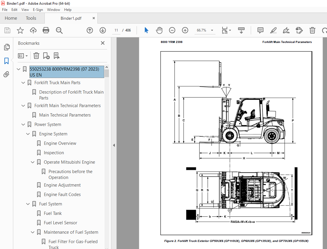

TABLE OF CONTENTS:
Yale Forklift A7T0 (GP110UX, GP135UX, GP155UX) Service Manual – PDF DOWNLOAD
550253238 8000YRM2398 (07 2023) US EN 1
Forklift Truck Main Parts 9
Description of Forklift Truck Main Parts 9
Forklift Main Technical Parameters 10
Main Technical Parameters 10
Power System 26
Engine System 26
Engine Overview 26
Inspection 36
Operate Mitsubishi Engine 36
Precautions before the Operation 36
Engine Adjustment 37
Engine Fault Codes 38
Fuel System 47
Fuel Tank 47
Fuel Level Sensor 50
Maintenance of Fuel System 50
Fuel Filter For Gas-Fueled Truck 50
Fuel Filter For Diesel-Fueled Truck 50
Fuel-Water Separator (Sediment Bowl) 51
Clean Fuel Tank 51
Maintenance of the Air Filter 51
Hydraulic Transmission Case and Torque Converter 52
Overview 54
Torque Converter 54
Hydraulic Clutch Unit 55
Control Valve 55
Transmission Case 56
Transmission Pump 56
Transmission Hydraulic Schematic 56
Speed Differential 59
Towing of Forklift Truck to be Repaired 60
Oil Inlet/Outlet Connection Location 60
Precautions in case of forklift failure 61
Trouble Shooting 61
Oil Port 64
Drive Axle 66
4-5T 66
5-7T 67
Steering System 74
Steering Axle 78
Brake System 82
Overview 83
Brake Master Cylinder 83
Wheel Brake 84
Automatic Clearance Regulator 85
Manual Brake 85
Adjustment of Brake Pedal 86
Maintenance 86
Disassemble, Wheel Brake 86
Inspect 88
Assemble, Wheel Brake 88
Test Automatic Clearance Regulator 90
Troubleshoot Wheel Brake 92
Hydraulic System 93
Main Pump 95
Multi-way Valve 95
Operation of Spool Valve 95
Primary Relief Valve 96
Steering relief valve 96
Action of Inclined Auto-lock Valve 97
Control Levers of Multi-way Control Valve 98
Hydraulic Oil Tank 98
Hydraulic System Main Oil Circuit 98
Lift Cylinder 102
Shut-off Valve 103
Speed Limit Valve 104
Tilting Cylinder 105
Main Oil Pump 105
Disassemble, Main Oil Pump 105
Assemble, Oil Pump 110
Test 110
Oil Filling Instructions 111
General Inspection Requirements 111
Inspection 111
Fill Level Requirements 111
Troubleshoot Hydraulic System 112
Lifting System 113
Inside and Outside Masts 114
Bracket 114
Safety Procedures When Working Near Mast 115
Adjustment for Lifting System 117
Lifting Cylinder 117
Carriage 117
Installation of Roller 118
Electrical System 120
Overview 120
Truck Operations 120
Start and Stop 120
Driving Operations 121
Combination Switch 121
Horn Button 121
Reverse Light and Signal 121
Light Controls 121
Steering Signal 121
Brake Signal 122
Dash Display 122
Introduction to PDM 127
Battery 127
Truck Safety System (OPS/Park Brake Alarm System) 128
Overview 128
Truck Will Not Start 129
Lift, Lowering and Tilt Functions are not Working 129
Forward and Back Functions are not Working 130
USB 130
Electrical Schematics 130
Troubleshoot with Electrical System 141
Diesel Particulate Filter (DPF) Regeneration Control (Only for the Trucks Equipped with Kubota V3800 Engine) 142
DPF Status 142
DPF Operation Instructions 143
DPF System Status Transiton 143
DPF Indicator Status 145
Drive, Operation, and Routine Maintenance of Forklift Truck 147
Transporting the Forklift Truck 147
Towing 147
Long-Term Storage of Forklift Truck 147
Procedures Prior to Operation 148
Precautions for Use 148
Cooling System 149
Oils Used for Forklift Truck 149
Hydraulic Oil Gauge Clarification and Oil Filling Instruction 152
General inspection requirements 152
Inspection method 152
Technical Requirements for filling Hydraulic Oil reservoir 152
Periodical Maintenance 153
550277201 0100YRM5001 (09 2023) US EN 181
General 187
Description 188
Hood, Seat, Floor Plate and Covers Replacement 190
Disassemble (4-5T Trucks) 190
Re-assemble 196
Steering Column 197
Description 197
Steering Column Repair 197
Disassemble 197
Disassemble Steering Hoses 199
Clean 200
Inspect 200
Re-assemble 200
Counterweight Replacement 201
Remove (4-5T Trucks) 201
Remove (5-7T Trucks) 203
Install (4-5T Trucks) 205
Install (5-7T Trucks) 205
Overhead Guard Replacement 206
Remove and Install 206
Operator Restraint System Replacement 209
Description 209
Emergency Locking Retractor (ELR) 209
Engine and Transmission Replacement 210
Remove 210
Disassemble (4-5T Trucks) 210
Disassemble (5-7T Trucks) 211
Re-assemble (4-5T Trucks) 213
Re-assemble (5-7T Trucks) 213
Exhaust System Repair 214
Remove and Disassemble Exhaust System 214
Inspect 214
Re-assemble Exhaust System 214
Cooling System 215
Description 215
Hydraulic Filter Assembly Repair 216
Disassemble 216
Clean and Inspect 217
Re-assemble 218
Fuel and Hydraulic Tanks Repair 219
Inspect 219
Clean 219
Steam Method of Cleaning 219
Chemical Solution Method of Cleaning 220
Additional Preparations for Repair 221
Small Leaks, Repair 221
Large Leaks, Repair 221
Preparations for Use After Repair 221
Safety Labels 222
550277204 0900YRM5004 (07 2023) US EN 227
Air-Intake and Exhaust System 233
Air-Intake and Exhaust System (Mitsubishi S6S and Mitsubishi S6S-T Engine) 233
Remove 233
Inspect 233
Install 233
Air-intake System (Kubota Engine) 235
Remove 235
Install 235
LPG Tank and Bracket Replacement with Swing-Out Bracket (Kubota WG3800 Engine) 236
Remove LPG Tank 236
Install LPG Tank 237
Remove LPG Bracket 237
Install LPG Bracket 238
Fuel Filter and Fuel Level Sensor Repair 239
FUEL FILTER ELEMENT (4-5T Trucks) 239
Remove 239
Install (4-5T Trucks) 240
Fuel Level Sensor (4-5T Trucks) 240
Remove (4-5T Trucks) 240
Install (4-5T Trucks) 240
FUEL FILTER ELEMENT (5-7T Trucks) 240
Remove 240
Install (5-7T Trucks) 241
Fuel Level Sensor (5-7T Trucks) 241
Remove (5-7T Trucks) 241
Install (5-7T Trucks) 241
LPG Converter (Kubota WG3800 Dual Fuel Engine) 242
Remove 242
Exhaust System 245
Remove (4-5T Trucks) 245
Install (4-5T Trucks) 247
Remove (5-7T Trucks) 251
Install (5-7T Trucks) 256
550286761 1600YRM5007 (09 2023) US EN 259
General 265
Steering Axle Assembly Repair 267
Remove 267
Disassemble (4-5T Trucks) 268
Disassemble (5-7T Trucks) 270
Clean 272
Inspect 272
Re-assemble (4-5T Trucks) 272
Re-assemble (5-7T Trucks) 273
Reinstall 274
Steering Cylinder Repair 275
Remove and Disassemble (4-5T Trucks) 275
Remove and Disassemble (5-7T Trucks) 276
Clean and Inspect 277
Assemble and Install (4-5T Trucks) 277
Assemble and Install (5-7T Trucks) 278
550286763 1900YRM5009 (07 2023) US EN 281
Cylinder 287
General 287
Safety Procedures When Working Near Mast 287
Integral Sideshift Cylinder Repair 287
Remove 287
Disassemble 289
Clean 289
Inspect 290
Re-assemble 290
Install 290
Check Integral Sideshift Cylinder Guide Sleeve Leak 290
Free-Lift Cylinder 291
Remove 291
Disassemble and Re-assemble 293
Clean 293
Inspect 294
Install 296
Main Lift Cylinder Repair 296
Remove 296
Disassemble and Re-assemble 298
Clean 298
Inspect 298
Install 299
MAIN LIFT CYLINDER LEAK CHECK 299
Tilt Cylinder Repair 299
Remove 299
Disassemble and Re-assemble 302
Clean 302
Inspect 302
Install 302
Hydraulic Gear Pump 303
General 303
Hydraulic Gear Pump Repair 304
Remove 304
Disassemble 306
Re-assemble 307
Examination and Repair 308
Pump Body 308
Bearing 309
Gear 310
Oil Seal 310
Main Control Valve 311
General 311
Main Control Valve 311
Description 311
Remove 313
Clean and Inspect 317
Install 317
550286764 2200YRM5010 (09 2023) US EN 319
General 325
Combination Switch 325
Remove and Install 325
Display and Rocker Switch 327
Remove and Install 327
Battery and Power Distribution Module 329
Remove and Install (4-5T Trucks) 329
Remove and Install (5-7T Trucks) 330
Auxiliary Relay and Fuse Box 331
Remove and Install 331
Sensors and Switches 332
General 332
Accelerator Pedal Position Sensor 332
Remove and Install 332
Parking Brake Sensor 332
Remove and Install 332
Fuel Level Sensor (4-5T Trucks) 333
Remove and Install 333
Fuel Level Sensor (5-7T Trucks) 334
Remove and Install 334
Torque Converter Temperature Sensor 335
Remove and Install 335
Engine Coolant Temperature Sensor 336
Remove and Install 336
Oil Pressure Sensor 338
Remove and Install 338
Lights 341
Lights 341
Remove and Install 341
550286765 4000YRM5011 (09 2023) US EN 343
General 349
Safety Procedures When Working Near Mast 350
Fork Replacement 351
Standard Carriage and Integral Sideshift Carriage 351
Remove 351
Install 352
Checks 352
Carriages Repair, Three-Stage FFL Mast 354
Standard Carriage 354
Remove 354
Clean and Inspect 354
Install 355
Integral Sideshift Carriage 355
Remove 355
Clean and Inspect 359
Assemble 359
Install 359
Three-Stage Mast With Full Free-Lift Repair 360
Remove 360
Disassemble and Re-assemble 361
Clean and Inspect 363
Carriage Adjustments 364
Lift Chains Adjustment 365
Mast Adjustments 366
Load Roller, Adjust 366
Mast Side Kicking, Adjust 367
550286769 8000YRM5015 (07 2023) US EN 369
Operator Station General Description and Principles of Operation 375
General Description and Location 375
Display Switch Cluster 377
Dash Display 377
Manual Control Levers 379
General Description 379
System Components 379
Lift/Lower 379
Tilt 379
Sideshift 379
Sideshift Fork Positioner 379
Accelerator Control 380
Description 380
Remove and Install 380
Combination Switch 380
Sequential Seatbelt Module 382
General Description 382
Seat Switch/Sensor 382
Buckle Switch 382
Sequential Seatbelt Module 382
Lighting 382
Front End, Mast 383
Description 383
Carriages 383
Description 383
Principles of Operation 383
Integral Sideshift Carriage 383
Mast Mounts 384
Description 384
Principles of Operation 384
Two-Stage Limited Free-Lift (LFL) Mast 386
Description 386
Principles of Operation 386
Two-Stage Full Free-lift (FFL) Mast 388
Description 388
Principles of Operation 388
Three-Stage Full Free-Lift (FFL) Mast 389
Description 389
Principles of Operation 389
Lift Cylinders 391
Description 391
Tilt and Sideshift Cylinders 394
Description 394
Tilt Cylinder 394
Sideshift Cylinder 394
Lowering Control Valves 394
Description 394
Chassis 395
Description 395
Examination and Maintenance 396
Leakage of Hydraulic Oil and Transmission Case Oil 396
Tire Air Pressure (Pneumatic Tire) 396
Wheel Hub Nut Torque 396
Overhead Guard 398
Coolant Level (Mitsubishi S6S Engine) 398
Engine Oil Level 398
Fan Belt Tension Level 398
Rear Combination Light 399
Hydraulic Oil Level 399
Pipeline Cylinder 399
Transmission Oil Level 399
Backrest 401
Fork and Fork Positioning Pin 402
Headlights 402
Gear-shift Handle 402
Multi-way Valve Operating Handle 402
Parking Brake Operation 402
Display Panel 402
Fuel Level 402
Lights 402
Turn Signal 403
Horn Pushbutton 403
Idle Stroke of Brake Pedal 403
Mast Operation 403
Lifting Chain Tension 403
Steering Wheel Free Stroke 403
Exhaust Gas 404
Inching Pedal (Hydraulic Transmission lift truck) 404
Brake 404
Steering Wheel 404
Parking Brake 404
Reversing light and Reversing Buzzer 404
Troubleshooting 405
More products