$40.95
Yale Forklift A814 (ERC_ERP16-20AAF) Service Manual – PDF DOWNLOAD
Yale Forklift A814 (ERC_ERP16-20AAF) Service Manual – PDF DOWNLOAD
FILE DETAILS:
Yale Forklift A814 (ERC_ERP16-20AAF) Service Manual – PDF DOWNLOAD
Language : English
Pages : 1260
Downloadable : Yes
File Type : PDF
PART NO. 524150790
IMAGES PREVIEW OF THE MANUAL:
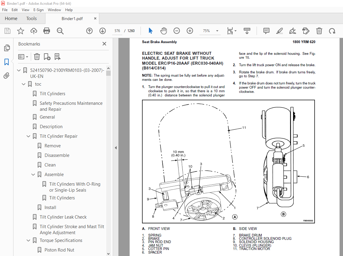
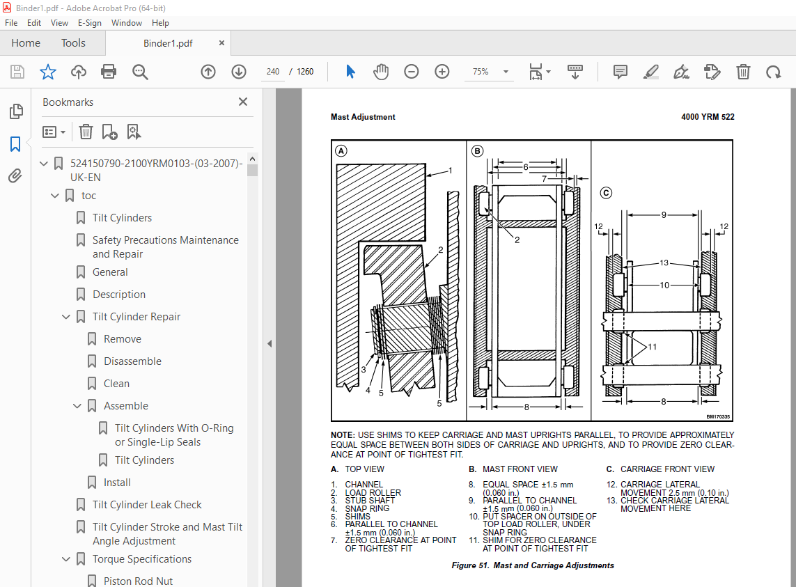
TABLE OF CONTENTS:
Yale Forklift A814 (ERC_ERP16-20AAF) Service Manual – PDF DOWNLOAD
524150790-2100YRM0103-(03-2007)-UK-EN 1
toc 1
Tilt Cylinders 1
Safety Precautions Maintenance and Repair 2
General 5
Description 5
Tilt Cylinder Repair 5
Remove 5
Disassemble 5
Clean 5
Assemble 6
Tilt Cylinders With O-Ring or Single-Lip Seals 6
Tilt Cylinders 7
Install 8
Tilt Cylinder Leak Check 10
Tilt Cylinder Stroke and Mast Tilt Angle Adjustment 11
Torque Specifications 11
Piston Rod Nut 11
Retainer 11
Troubleshooting 12
tables 1
Table 1 Movement Rates (Maximum) for Tilt Cylinders 10
524150797-8000YRM0231-(02-2023)-UK-EN 17
General 23
Threaded Fasteners 23
Nomenclature, Threads 23
Strength Identification 24
Cotter (Split) Pins 25
Fastener Torque Tables 30
Conversion Table 32
524158040-2240YRM0001-(01-2023)-UK-EN 39
General 45
Battery Type 45
Lead-Acid Batteries 45
Lithium-Ion Batteries 46
Specific Gravity 46
Chemical Reaction in a Cell 46
Electrical Terms 48
Battery Selection 49
Battery Voltage 50
Battery as a Counterweight 50
Battery Ratings 50
Kilowatt-Hours 50
Battery Maintenance 51
Safety Procedures 51
Maintenance Records 51
New Battery 51
Cleaning Battery 52
Adding Water to Battery 54
Hydrometer 54
Battery Temperature 55
Charging Battery 56
Types of Battery Charges 57
Methods of Charging 58
Troubleshooting Charger 59
Knowing When Battery Is Fully Charged 59
Where to Charge Batteries 59
Equipment Needed 59
Battery Connectors 60
Battery Care 60
Troubleshooting 62
524158753-1600YRM0720-(11-2006)-UK-EN 67
toc 67
Steering Housing and Control Unit 67
Safety Precautions Maintenance and Repair 68
General 71
Description 71
Operation 72
Steering Wheel and Column Assembly Repair 73
Assembly Components, Remove 73
Steering Control Unit, Disassemble 78
Steering Control Unit, Clean 78
Steering Control Unit, Assemble 78
Assembly Components, Install 80
System Air Removal 82
Troubleshooting 82
524158757-2200YRM0514-(01-2004)-UK-EN 87
toc 87
Instrument Cluster 87
Safety Precautions Maintenance and Repair 88
General 91
Description 91
Instrument Cluster Display Panel, Internal Combustion Lift Truck 91
Instrument Cluster Display Panel, Electric Lift Truck Models 98
Optional Basic Display Panel 98
Features of the Optional Basic Display Panel 98
Description of Features on the Optional Basic Display Panel 98
Standard Display Panel 99
Features of the Standard Display Panel 99
Description of Features on the Standard Display Panel 99
Premium Display Panel 100
Features on the Premium Display Panel 100
Description of Features on the Premium Display Panel 101
Curtis 1215 Display Panel 103
Description and Features 103
Operation 104
Cluster-Type Display Panel (Internal Combustion) Replacement 105
Remove 105
Install 105
Cluster Display Panel (Electric Lift Truck) Replacement 108
Curtis 1215 Display Panel Replacement 113
Remove 113
Install 113
tables 87
Table 1 Instrument Cluster, Internal Combustion 92
524158890-4000YRM0521-(03-2006)-UK-EN 117
toc 117
Mast 117
Safety Precautions Maintenance and Repair 118
General 121
Description and Operation 121
Carriages 121
Mast Mounts 123
Two-Stage Mast, Limited Free-Lift (LFL) 124
Description and Operation 124
Two-Stage Mast, Full Free-Lift (FFL) 126
Description and Operation 126
Three-Stage Mast, Full Free-Lift (FFL) 128
Description and Operation 128
Four-Stage Mast 130
Description and Operation 130
Cylinder Cushion During Lifting Sequence 134
Cylinder Cushion During Lowering Sequence 135
524158891-4000YRM0522-(07-2010)-UK-EN 139
toc 139
Mast 139
Safety Precautions Maintenance and Repair 140
General 143
Safety Procedures When Working Near Mast 144
Fork Repair 146
Remove 146
Install 146
Carriages Repair 148
Standard Carriage, Remove 148
Hang-On Sideshift Carriage, Remove 149
Standard Carriage and Hang-On Sideshift Carriage, Repair 150
Standard Carriage, Install 151
Hang-On Sideshift Carriage, Install 152
Integral Sideshift Carriage 152
Remove 152
Clean and Inspect 156
Repair 157
Install 158
Mast Repair 159
Remove 159
Two-Stage LFL and Two-Stage FFL Masts, Disassemble 161
Three-Stage FFL Mast 169
Disassemble 169
Mast and Chains, Clean and Inspect 172
Two-Stage LFL and Two-Stage FFL Mast, Assemble 173
Three-Stage FFL Mast, Assemble 174
Install 175
Lift Cylinders Repair 177
Main Lift Cylinders, Remove 177
Free-Lift Cylinder, Remove 177
Cylinders, Disassemble 178
Two-Stage Full Free-Lift Mast, Right-Hand Main Lift Cylinder 178
Two-Stage Full Free-Lift Mast, Left-Hand Main Lift Cylinder 180
Two-Stage Limited Free-Lift Mast and Three-Stage Full Free-Lift 180
Two-Stage Limited Free-Lift Mast and Three-Stage Full Free-Lift 181
Two-Stage Full Free-Lift Mast and Three-Stage Full Free-Lift Mas 182
Clean and Inspect 183
Cylinders, Assemble 183
Two-Stage Full Free-Lift Mast, Right-Hand Main Lift Cylinder 183
Two-Stage Full Free-Lift Mast, Left-Hand Main Lift Cylinder 184
Two-Stage Limited Free-Lift Mast and Three-Stage Full Free-Lift 185
Two-Stage Limited Free-Lift Mast and Three-Stage Full Free-Lift 185
Two-Stage Full Free-Lift Mast and Three-Stage Full Free-Lift Mas 186
Main Lift Cylinders, Install 187
Free-Lift Cylinder, Install 187
Header Hose Arrangements 188
Two-Stage LFL Mast, New Hose Install 188
Two-Stage LFL Mast, Adjust Hoses After Installation 193
Two-Stage FFL Mast, New Hose Install 193
Two-Stage FFL Mast, Adjust Hoses After Installation 201
Three-Stage FFL Mast, New Hose Install 201
Three-Stage FFL Mast, Adjust Hoses After Installation 212
Header Hose Arrangement 213
Two-Stage LFL Mast, New Hose Install 213
Two-Stage LFL Mast, Adjust Hoses After Installation 218
Two-Stage FFL Mast, New Hose Install 218
Two-Stage FFL Mast, Adjust Hoses After Installation 224
Three-Stage FFL Mast, New Hose Install 224
Three-Stage FFL Mast, Adjust Hoses After Install 233
Lift and Tilt System Leak Check 234
Lift Cylinders Leak Check 234
Tilt Cylinders Leak Check 234
Tilt Cylinders Adjustment 235
Lift Chains Adjustment 237
Mast Adjustment 239
Carriage Adjustment 241
Troubleshooting 242
tables 139
Table 1 Hook-Type Carriage Chain Adjustment 237
Table 2 Pin-Type Carriage Chain Adjustment 238
524166836-1600YRM0485-(07-2003)-UK-EN 245
toc 245
Steering System for Electric Lift Trucks 245
Safety Precautions Maintenance and Repair 246
General 249
Description 251
Steering Wheel and Column Assembly Repair 252
Assembly Components, Remove 252
Assembly Components, Install 256
Power Steering Motor and Pump 257
Description 257
Remove and Disassemble, Models ERC 20-30AGF (ERC040-065RF/ZF, RG 258
Remove and Disassemble, Models ERC35-55HG (ERC70-120HD, ERC70-12 259
Remove and Disassemble, Models ERP20-30ALF 262
Remove and Disassemble, Models ERC/P16-20AAF (ERC040-065AF, AG/B 262
Assemble and Install, All Models With A Vertical Mount Except ER 263
Assemble and Install, Models ERP20-30ALF 263
Assemble and Install, Models ERC/P16-20AAF (ERC030-040AF, AG/BG) 264
Power Steering Pump, Repair 264
Seal, Replace 265
Hydraulic Steering Motor 266
Steering System Air Removal 266
Steering Pressure Check 266
Optical Encoder and Activator Circuits Check 267
Troubleshooting 269
524166840-2200YRM0560-(07-2005)-UK-EN 273
toc 273
Electrical System 273
Safety Precautions Maintenance and Repair 274
General 279
Description 280
ZX Series Display Panels 280
Optional Basic Display Panel 280
Features of the Optional Basic Display Panel 280
Description of Features on the Optional Basic Display Panel 280
Standard Display Panel 281
Features of the Standard Display Panel 281
Description of Features on the Standard Display Panel 281
Premium Display Panel 282
Features on the Premium Display Panel 282
Description of Features on the Premium Display Panel 283
Curtis 1215 Display Panel 285
Description and Features 285
Operation 285
SEM Display Panels – Features 286
Descriptions of Common Features 287
LED Symbol Indicators – SEM 287
LCD Screen 287
Battery Discharge Indicator (BDI) 287
Service Reminder 288
Status Codes 288
Hourmeter 288
Additional Features of Premium Display Panel 289
Descriptions of Additional Features 289
LCD Screen 289
Operator Passwords 289
Daily Checklist and Service Items 289
Performance Modes 289
Status Code Lists 290
Adjustment of BDI 290
SEM Display Panel Indicators 290
All Indicator Symbols 290
Hourmeter Indicator Symbol 290
Wrench Symbol 290
Battery Symbol 290
Battery Discharge Indicator (BDI) 290
Brake Fluid Too Low Symbol 290
Parking Brake Symbol 290
Fasten Seat Belt Symbol 291
LCD Screen (Standard Display Panel) 291
Additional Components of Premium Display Panel 291
Alpha Numerical Screen 291
STAR Push Button 291
Push Buttons ##1 Through ##5 – SEM 291
Other Control Components 291
Display Panel Components – ZX, and Curtis Replacement 292
ZX Panel Replacement 292
Curtis 1215 Display Panel Replacement 297
Remove 297
Install 297
SEM Display Panel Replacement 298
Motor Controller (SR or SP) Replacement 298
Remove 298
Install 298
Control Components Replacement 300
Start Switch, Replace 300
Brake Light Switch, Replace 301
Seat Switch, Replace 301
External Seat Switch, Adjust 302
Switch for Optional Seat Brake, Replace 303
Parking Brake Switch, Replace 303
Direction Switches Foot Directional Control Replace 304
Direction Control Switches (Steering Column), Replace 305
Direction Control Switches, ERC070-120HG (Steering Column), Repl 306
Brake Fluid Switch, Replace 306
Brush Wear and Overtemperature Sensors 306
Rocker Switches for Lights 307
Accelerator Position Sensor, Replace 307
On-Demand Steering Components 309
Lights, Converter, Relay, and Reverse Alarm 311
Incandescent Brake, Tail, and Reverse Light Assembly, Replace 311
LED Brake, Tail, and Reverse Light Assembly, Replace 313
Remove 313
Install 313
Flashing Light Assembly, Replace 313
Front, Rear Driving Light, or Spot Light Assemblies, Replace 315
Operator Compartment Light Assembly, Replace 315
Converter, Replace 316
Relay, Replace 316
Reverse Alarm, Replace 316
Horn and Horn Button 316
Horn Switch and Cover 317
Hydraulic Pump Switches 317
Control and Power Fuses Check 318
ZX Motor Controllers 318
SEM Motor Controllers 318
SEM Controller Field Diagnostic Procedure 323
Armature FET Test 323
Field FET Test 323
Brush Wear and Overtemperature Sensors Check – ZX Motor Controll 327
Thermal Sensors – SEM Motor Controllers Check 328
Start Switch Adjustment 329
Accelerator Potentiometer and Start Switch, ERC070-120HG Lift Tr 330
ERC070-120HG 330
Direction Switches Foot Directional Control Pedal 331
Brake Light Switch Adjustment 332
Seat Switch Check 333
Optional Seat Brake Switch Adjustment 333
Parking Brake Switch Adjustment 334
Direction Switches Check 334
Foot Directional Control Pedal 334
Steering Column 335
Hydraulic Pump Switch Adjustment 335
Foot Directional Control or Accelerator Pedal Adjustment 335
Accelerator Position Sensor Adjustment 336
524166844-2200YRM0942-(08-2007)-UK-EN 341
toc 341
Display Panel for SEM Controls 341
Safety Precautions Maintenance and Repair 342
General 345
SEM Display Panel Features 345
Descriptions of Common Features 345
LED Symbol Indicators 345
LCD Screen 345
Battery Discharge Indicator (BDI) 346
Service Reminder 346
Status Codes 346
Hourmeter 346
Additional Features of Premium Display Panel 346
Descriptions of Additional Features (Available With Premium Disp 346
LCD Screen 346
Operator Passwords 347
Daily Check List and Service Items 347
Performance Modes 347
Status Code Lists 347
Adjustment of BDI 347
SEM Display Panel Indicators 348
All Indicator Symbols 348
Hourmeter Indicator Symbol 348
Wrench Indicator Symbol 348
Battery Indicator Symbol 348
Battery State-of-Charge (BDI) 348
Brake Fluid Too Low Symbol 349
Parking Brake Symbol 349
Fasten Seat Belt Symbol 349
LCD Screen (Standard Display Panel) 350
Additional Components of Premium Display Panel 350
Alphanumeric Screen 350
STAR Push Button 350
Push Buttons 1 Through 5 350
Adjustments With a Computer 350
Computer System 350
Connect PC to SEM Display Panel 351
ITW Switches Windows Software Program (for SEM Display Panel) 352
Description 352
Getting Help 352
Hardware and Software Requirements 352
Install 352
How to Start ITW Switches Program 352
Menus 356
Sample Sessions 365
Replacement 387
SEM Display Panel 387
Remove and Replace 387
tables 341
Table 1 Adapter Pins (DB25F to DB9) 351
524167640-2200YRM0947-(08-2007)-UK-EN 393
toc 393
Troubleshooting and Adjustments With a Computer 393
Safety Precautions Maintenance and Repair 394
Computer System 397
Connect a PC to a Control Card 398
Installation 399
SMARTSET™ Windows Software Program 399
How to Start the Program 399
DEMO Mode 400
Selecting the Communications Port 402
Verification of Controller and Lift Truck 403
Select Lift Truck Series 405
Controller Card Register Parameter List 406
How to Change a Parameter 407
How to Save a Changed Parameter File 408
How to Load a Saved Parameter File 410
How to Show and Remove Saved Parameter Files 410
How to Return to Factory Default Settings 411
How to Save Changes to Control Card 412
How to View Status Codes 413
Saving Status Codes 414
How to Show and Remove Saved Status Code Files 415
Closing and Clearing Status Code List 416
How to View Saved Register Data and Saved Status Data 417
How to Save Register Data and Status Code Data In RTF and TXT 419
GE Sentry™ Software Program 420
Installation 420
Description 420
How to Start GE SENTRY Program 420
How to Reset MIN and MAX Display 425
Graphing Mode 426
How to Exit GE SENTRY Program 427
tables 393
Table 1 Cable Connections – Computer to Control 397
Table 2 Adapter Pins (DB25F to DB9) 398
Table 3 Plug-Z Connection 399
524179936-0100YRM0617-(03-2006)-UK-EN 431
toc 431
Frame 431
Safety Precautions Maintenance and Repair 432
General 435
Description 435
Main Frame 435
Other Frame Weldments 445
Overhead Guard 446
Overhead Guard Replacement 451
Remove 451
Install 452
Battery and Operator Restraint System, Hood and Seat Brake, and 452
Battery Restraint System 452
Hood and Seat Brake 454
Hood With E-Hydraulics 455
Operator Restraint System and Seat Assembly 456
Automatic Locking Retractor (ALR) 456
Emergency Locking Retractor (ELR) 456
Counterweight Replacement 457
Remove 457
Install 459
Traction Motor Replacement 460
Remove 460
Install 462
Hydraulic Tank Repair 463
Inspect 463
Clean 464
Steam Method 464
Chemical Solution Method 464
Additional Preparations for Repair 465
Small Leaks, Repair 465
Large Leaks, Repair 465
Preparations for Usage After Repair 465
Painting Instructions 465
Safety Label Replacement 467
Battery Specifications 469
tables 431
Table 1 Counterweights 458
524179939-1400YRM0618-(03-2006)-UK-EN 473
toc 473
Drive Axle, Speed Reducer, and Differential 473
Safety Precautions Maintenance and Repair 474
General 477
Description 477
Drive Unit Assembly Repair 477
Remove Complete Drive Unit Assembly as a Unit 477
Traction Motor, Remove 478
Drive Unit and Speed Reducer, Remove 480
Drive Axle, Disassemble 481
Differential and Speed Reducer, Disassemble 481
Clean 484
Inspect 484
Assembly of Drive Unit 484
Find Correct Shim Set for Hypoid Gear 484
Pinion, Assemble and Install 485
Differential and Ring Gear, Assemble and Install 486
Input Gear for Speed Reducer, Assemble 490
Drive Axle and Hub Assembly, Assemble 491
Installation of Drive Unit 492
Drive Unit, Install 492
Traction Motor, Install 493
Torque Specifications 494
Troubleshooting 495
tables 473
Table 1 Shims Adjustment for Pinion 485
Table 2 Ring and Pinion Tooth Contact Adjustment 489
524179940-1600YRM0619-(03-2006)-UK-EN 499
toc 499
Steering Axle 499
Safety Precautions Maintenance and Repair 500
General 503
Description 503
Steering Axle Assembly Repair 504
Remove 504
Install 504
Wheels and Hubs Repair 505
Remove and Disassemble 505
Clean 505
Assemble and Install 505
Spindles, Bearings, and Links Repair 509
Remove and Disassemble; Lift Truck Models ERC/P16-20AAF (A814/B8 509
Clean 509
Assemble and Install; Lift Truck Models ERC/P16-20AAF (A814/B814 509
Remove and Disassemble; Lift Truck Models ERC030-040AF and ERC03 511
Clean 511
Inspect 511
Assemble and Install; Lift Truck Models ERC030-040AF and ERC030- 511
Steering Cylinder Repair 513
Remove and Disassemble 513
Clean and Inspect 513
Assemble and Install 513
Torque Specifications 514
Troubleshooting 515
524179941-1600YRM0512-(07-2003)-UK-EN 519
toc 519
Steering Housing and Control Unit 519
Safety Precautions Maintenance and Repair 520
General 523
Description 523
Operation 524
Steering Wheel and Column Assembly Repair 525
Steering Column Assembly, Remove 525
Steering Control Unit 530
Disassemble 530
Clean 533
Assemble 534
Install 541
Steering Column Assembly, Install 543
System Air Removal 544
Remove 544
Troubleshooting 544
524179944-1800YRM0620-(03-2008)-UK-EN 549
toc 549
Brake System 549
Safety Precautions Maintenance and Repair 550
General 553
Description and Operation 553
Service Brakes 553
Master Cylinder 553
Parking Brake 555
Service Brakes Repair 555
Remove and Disassemble 555
Clean 558
Inspect 558
Assemble and Install 559
Master Cylinder Repair 562
Remove 562
Disassemble 563
Clean and Inspect 565
Assemble 565
Install 568
Parking Brake Repair 568
Remove and Dissemble 568
Assemble and Install 568
Parking Brake Switch Replacement 572
Brake System Air Removal 572
Service Brakes Adjustment 573
Brake Pedal Adjustment 573
Master Cylinder Adjustment 574
Parking Brake Adjustment 574
Parking Brake Switch Adjustment 574
Parking Brake Not Applied Switch Test 574
Seat Brake Assembly 574
Seat Brake, Adjust – Lift Truck Models ERC/P16-20AAF (ERC030-040 574
Brake Switch, Adjust – Lift Truck Models ERC/P16-20AAF (ERC030-0 575
Electric Seat Brake Without Handle, Adjust for Lift Truck Model 576
Electric Seat Brake With Handle for Lift Truck Model ERC/P16-20A 577
Remove 577
Clean 577
Inspect 577
Install 579
Adjustments 579
Solenoid Adjustment 579
Traction cutoff Switch Adjustment 579
Cable Adjustment 580
Torque Specifications 582
Troubleshooting 582
524179945-1900YRM0559-(04-2009)-UK-EN 589
toc 589
Hydraulic System 589
Safety Precautions Maintenance and Repair 590
General 593
Description 593
Hydraulic System 593
Operation 601
Hydraulic System 601
Hydraulic Gear Pump 607
Steering Pump 607
Hydraulic Tank Repair 615
Tank, Remove [ERC/P16-20AAF (ERC030-040AF, AG/BG) (A814); ERC/P1 615
Tank, Remove [ERP20-30ALF (B216) and ERP20-30ALF (ERP040-060DH) 617
Tank, Remove [ERP20-32ALF (ERP040-065DH) (E216)] 618
Hydraulic Tank [ERC35-55HG (ERC70-120HH) (B839/C839)] 618
Inspect 619
Small Leaks, Repair 620
Large Leaks, Repair 620
Clean 620
Steam Method 620
Chemical Solution Method 621
Additional Methods for Tank Repair 621
Tank, Install [ERC/P16-20AAF (ERC030-040AF, AG/BG) (A814); ERC/P 621
Tank, Install [ERP20-30ALF (B216) and ERP20-30ALF (ERP040-060DH) 622
Tank, Install [ERP20-32ALF (ERP040-065DH) (E216)] 622
Filter Replacement 623
All Lift Trucks Except [ERC35-55HG (ERC70-120HH) (B839/C839); ER 623
Remove 623
Install 624
Lift Truck Models [ERC35-55HG (ERC70-120HH) (B839/C839)] 624
Remove 624
Install 624
Lift truck Models [ERC20-32AGF (ERC040-065GH) (A908) and ERC/P16 625
Remove 625
Install 625
Lift Truck Models [ERP20-32ALF (ERP040-065DH) (E216)] 627
Remove 627
Install 627
Hydraulic Pump Repair 630
Hydraulic Pump, Remove [ERC/P16-20AAF (ERC030-040AF, AG/BG) (A81 630
Hydraulic Pump, Disassemble ERC/P16-20AAF (ERC030-040AF, AG/BG) 630
Inspect 632
Clean 632
Pump Seal Replace and Pump Assemble 632
Assemble Pump on Motor 632
Hydraulic Pump and Motor, Install [ERC/P16-20AAF (ERC030-040AF, 634
Hydraulic Pump, Remove [ERP20-30ALF (B216); ERP20-30ALF (ERP040- 635
Hydraulic Pump, Disassemble [ERC35-55HG (ERC70-120HH) (B839/C839 636
Hydraulic Pump, Inspect [ERC35-55HG (ERC70-120HH) (B839/C839) an 638
Hydraulic Pump, Clean [ERC35-55HG (ERC70-120HH) (B839/C839) and 638
Hydraulic Pump, Assemble [ERC35-55HG (ERC70-120HH) (B839/C839) a 638
Hydraulic Pump and Motor, Install [ERP20-30ALF (B216); ERP20-30A 638
Main Control Valve Repair 640
Steering Pump Repair 640
Pump, Remove and Disassemble [ERC/P16-20AAF (ERC030-040AF, ERC03 640
Pump, Remove and Disassemble [ERP20-30ALF (B216); ERP20-30ALF (E 642
Pump, Assemble and Install 644
Steering Control Unit Replacement 645
Remove 645
Install 645
Steering Cylinder Repair 651
Main Control Valve Check and Adjust 651
Steering Relief Valve Check and Adjust 652
Specifications 652
Relief Valve Pressures* 652
Hydraulic Tank Capacity (dipstick full mark) 653
Hydraulic Pump Capacities – All Models Except ERC35-55HG (ERC70- 653
Hydraulic Pump Capacities – Models ERC35-55HG (ERC70-120HH) (B83 653
Troubleshooting 653
Steering 653
Steering Housing and Steering Control Unit 654
Hydraulic System 655
524179946-2000YRM0562-(02-2009)-UK-EN 661
toc 661
Manual hydraulic Control Valve 661
Safety Precautions Maintenance and Repair 662
General 665
Description 665
Operation 668
ERC/P16-20AAF (ERC030-040AF, AG/BG) (A814); ERC/P16-20AAF (ERC03 668
ERP20-30ALF (B216), ERP20-30ALF (ERP040-060DH) (D216) and ERP20- 668
Lift Section 670
Tilt Section 670
Tilt Backward 670
Tilt Forward 670
Relief Valve 672
Main Control Valve Repair 673
Main Control Valve Without OPS Solenoid 673
Remove 673
Disassemble 673
Clean and Inspect 677
Assemble 677
Install [ERC/P16-20AAF (ERC030-040AF, AG/BG) (A814); ERC/P16-20A 678
Install [ERP20-30ALF (B216), ERP20-30ALF (ERP040-060DH) (D216) a 678
Main Control Valve With OPS Solenoid 679
Remove 679
Disassemble 679
Clean and Inspect 681
Relief Valve Repair 683
Assemble 684
Install 685
Control Lever Linkage Repair 685
Remove [ERC/P16-20AAF (ERC030-040AF, AG/BG) (A814),ERC/P16-20AAF 685
Disassemble [ERC/P16-20AAF (ERC030-040AF, AG/BG) (A814),ERC/P16- 685
Assemble and Install [ERC/P16-20AAF (ERC030-040AF, AG/BG) (A814) 687
Control Valve Linkage Repair 687
Remove and Disassemble [ERC/P16-20AAF (ERC030-040AF, AG/BG) (A81 687
Assemble and Install [ERC/P16-20AAF (ERC030-040AF, AG/BG) (A814) 688
Control Lever Linkage Repair 688
Remove [ERP20-30ALF (B216), ERP20-30ALF (ERP040-060DH) (D216) an 688
Disassemble [ERP20-30ALF (B216), ERP20-30ALF (ERP040-060DH) (D21 690
Assemble and Install [ERP20-30ALF (B216), ERP20-30ALF (ERP040-06 690
Pressure Relief Valve Check and Adjustment 691
Primary Relief Valve 691
Secondary Relief Valve 692
Troubleshooting 693
524179947-2200YRM0557-(07-2003)-UK-EN 697
toc 697
EV-100ZX™ SCR Motor Controller 697
Safety Precautions Maintenance and Repair 698
General 703
Model Number Data For EV-100ZX Controller 704
Register Parameters 718
General 718
Function Numbers 718
Control Card, Checks and Adjustments 718
Handset 719
How to Check and Adjust Registers 719
How to Scroll through Fault Codes and Clear Them 719
Checks and Adjustments on Workbench 720
When Handset Is Connected to Control Card Installed In Lift Truc 721
Function Numbers 1 through 15 722
Function Numbers 16 through 30 722
Function Numbers 48 through 62 722
Control Cards 723
Function Number Descriptions 723
Traction Control Cards (Label Letters – ZH and ZY) 723
Function Number 1 STORED STATUS CODE 723
Function Number 2 CREEP SPEED 723
Function Number 3 CONTROLLED ACCELERATION AND 1A TIME 723
Function Number 4 CURRENT LIMIT 724
Function Number 5 PLUGGING DISTANCE (CURRENT) 724
Function Number 6 1A DROP OUT CURRENT 724
Function Number 7 FIELD WEAKENING PICK UP 724
Function Number 8 FIELD WEAKENING DROP OUT 724
Function Number 9 REGENERATIVE BRAKING CURRENT LIMIT 724
Function Number 10 REGENERATIVE BRAKING START 725
Function Number 13 SPEED LIMIT 3 (SL3) 725
Function Number 14 INTERNAL RESISTANCE COMPENSATION 725
Function Number 15 BATTERY VOLTS 726
Function Numbers GREATER THAN 15 726
Function Number 16 PEDAL POSITION PLUG 726
Function Number 17 CARD TYPE SELECTION 726
Function Number 18 STEERING PUMP TIME DELAY 726
Function Number 19 MAINTENANCE ALERT (Tens/Units) 727
Function Number 20 MAINTENANCE ALERT (Thousands/Hundreds) 727
Function Number 21 MAINTENANCE SPEED LIMIT 727
Function Numbers 22 Through 28 TEMPORARY DATA REGISTERS 727
Function Number 29 HOURMETER (Tens/Units) 727
Function Number 30 HOURMETER (Thousands/Hundreds) 727
Function Number 48 Through 62 SET LIFT TRUCK PERFORMANCE 727
Function Number 48 CONTROLLED ACCELERATION AND 1A TIME 728
Function Number 49 FIELD WEAKENING PICK UP 728
Function Number 50 SPEED LIMIT 1 728
Function Number 52 CONTROLLED ACCELERATION AND 1A TIME 728
Function Number 53 FIELD WEAKENING PICK UP 728
Function Number 54 SPEED LIMIT 1 729
Function Number 56 CONTROLLED ACCELERATION AND 1A TIME 729
Function Number 57 FIELD WEAKENING PICK UP 729
Function Number 58 SPEED LIMIT 1 729
Function Number 60 CONTROLLED ACCELERATION AND 1A TIME 729
Function Number 61 FIELD WEAKENING PICK UP 729
Pump Control Card (Label Letter ZP) 729
Function Number 1 STORED STATUS CODE 730
Function Number 2 INTERNAL RESISTANCE COMPENSATION START 730
Function Number 3 CONTROLLED ACCELERATION 730
Function Number 4 CURRENT LIMIT 730
Function Number 7 CONTROLLED ACCELERATION COMPENSATION 730
Function Number 11 SPEED LIMIT 1 (SL1) (Slow Speed) – Tilt and S 730
Function Number 12 SPEED LIMIT 2 (SL2) (Medium Speed) – Slow Lif 730
Function Number 13 SPEED LIMIT 3 (SL3) 730
Function Number 14 SPEED LIMIT 4 (SL4) Fast Lift 731
Function Numbers Greater Than 15 731
Function Number 16 INTERNAL RESISTANCE COMPENSATION 731
Function Number 17 CARD TYPE SELECTION 731
Function Numbers 18 through 28 TEMPORARY DATA REGISTERS 731
Function Number 29 HOURMETER (Tens/Units) 731
Function Number 30 HOURMETER (Thousands/Hundreds) 731
Function Number 48 CONTROLLED ACCELERATION 732
Function Number 49 SPEED LIMIT 2 732
Function Number 50 SPEED LIMIT 3 732
Function Number 52 CONTROLLED ACCELERATION 732
Function Number 53 SPEED LIMIT 2 732
Function Number 54 SPEED LIMIT 3 732
Function Number 56 CONTROLLED ACCELERATION 732
Function Number 57 SPEED LIMIT 2 732
Function Number 58 SPEED LIMIT 3 732
Function Number 60 CONTROLLED ACCELERATION 733
Function Number 61 SPEED LIMIT 2 733
Function Number 62 SPEED LIMIT 3 733
Register Parameters 733
Troubleshooting 733
General 733
Status Codes 734
Register Maps 736
Status Code Charts 747
EV-100ZX SCR Motor Controller Repair 788
Fuses 788
SCR, Check 788
SCR Assembly 790
Thermal Protector 790
SCR 1 Assembly, Replace 790
OFF Circuit for SCR 1 791
Reactor Assembly, Check 791
Suppressors for SCR 2 and SCR 5, Check 791
SCR 2 and SCR 5, Check 791
SCR 2 and SCR 5, Replace 792
Capacitor C1, Check 792
Diodes D3 and D4 792
Diodes D3 and D4, Check 792
Diodes D3 and D4, Replace 792
Motor Current Sensor 792
Contactors 793
Contactor, Repair 793
Control Card 795
Control Card Plugs 796
Brush Wear Indicators 796
Theory of Operation 797
Electronic Speed Controls 797
Silicon Controlled Rectifier (SCR) 798
Motor Circuit That Operates With Pulses 799
Traction Circuit 800
Hydraulic Pump Motor 800
SCR 1 OFF Circuit 800
SCR 1 OFF Operation 801
Induction Current from Motor 803
Control Cards 804
Pulse Monitor Trip (PMT) (Traction Circuit Only) 804
SRO Circuit (Traction Circuit Only) 804
Sequence of Operation 805
Control Card Adjustments (Traction Circuit) 805
Accelerator Control 809
SCR Control (Hydraulic Pump Motor) 809
Contactors 809
Circuit Protection 810
Traction Circuit Fuse 810
Current Limit 810
Thermal Protection 810
Suppressors 811
Truck Management Module (TMM1) 811
Display Panels 812
Display Panel 812
Optional Basic Display Panel 812
Features of the Optional Basic Display Panel 812
Description of Features on the Optional Basic Display Panel 813
Standard Display Panel 813
Features of the Standard Display Panel 813
Description of Features on the Standard Display Panel 814
Premium Display Panel 815
Features on the Premium Display Panel 815
Description of Features on the Premium Display Panel 816
Curtis 1215 Display Panel 818
Description and Features 818
Operation 819
tables 697
Table 1 Terminal and Plug Wire Connections for Control Card ZY, 710
Table 2 Terminal and Plug Wire Connections for Control Card ZH, 712
Table 3 Terminal and Plug Wire Connections for Control Card ZH, 714
Table 4 Terminal and Plug Wire Connections for Controller with 716
Table 5 Status Codes List 735
Table 6 Register Map for Control Cards ZH and ZY (Traction) 737
Table 7 Register Map for Control Card ZP (Hydraulic Pump) 742
Table 8 Terminal and Plug Wire Connections for TMM1 Module 812
524179950-2200YRM0624-(07-2003)-UK-EN 823
toc 823
EV-100ZX TM SCR MOTOR CONTROLLER 823
Safety Precautions Maintenance and Repair 824
Register Parameters 827
General 827
Function Numbers 828
Control Card Checks and Adjustments 828
Register Parameter Tables 829
tables 823
Table 1 EV-100ZX Parameters [Heavy Duty Motor ( Yale Part Numbe 829
Table 2 EV-100ZX Parameters [Heavy Duty Motor ( Yale Part Numbe 833
Table 3 EV-100ZX Parameters [Standard Motor ( Yale Part Number 837
Table 4 EV-100ZX Parameters [Standard Motor ( Yale Part Number 841
Table 5 EV-100ZX Parameters [Standard Motor ( Yale Part Number 845
Table 6 EV-100ZX Parameters (Standard System) (Hydraulic Pump C 849
Table 7 EV-100ZX Parameters (Low Energy System) (Hydraulic Pump 852
524179951-2200YRM0724-(04-2005)-UK-EN 857
toc 857
SR/SP Transistor Motor Controllers 857
Safety Precautions Maintenance and Repair 858
Description 863
General 863
Model Number Data for SR/SP Transistor Motor Controllers 864
Motor Controller Checks and Adjustments 867
Checks and Adjustments Using Handset 867
General 867
Connect Handset 868
Start Sequence 868
Check or Delete Stored Status Codes 869
Returning Lift Truck to Normal Operation 871
Workbench Checks and Adjustments 871
How to Check and Adjust Registers 873
Function Parameters Adjustments 873
General 873
Function Numbers 874
When Handset is Connected to Motor Controller in Lift Truck 874
Function Numbers 1 through 15 874
Function Numbers 16 through 30 874
Function Numbers 48 through 63 875
Function Number Descriptions 876
Traction Motor Controller (Label Letter – SR) 876
Function Number 01 AUTO REGEN ENABLE SPEED 876
Function Number 02 CREEP SPEED 876
Function Number 03 CONTROLLED ACCELERATION 876
Function Number 04 ARMATURE CURRENT LIMIT 876
Function Number 05 REGEN RAMP RATE 877
Function Number 06 FIELD WEAKENING (FW) RATIO 877
Function Number 07 MINIMUM FIELD CURRENT 877
Function Number 08 MAXIMUM FIELD CURRENT 877
Function Number 09 REGENERATIVE BRAKING CURRENT LIMIT (C/L) 877
Function Number 10 FIELD CURRENT FOR REGENERATIVE BRAKING 877
Function Number 12 MAXIMUM ARMATURE % ON TIME (Travel Speed Limi 877
Function Number 13 SPEED LIMIT 3 878
Function Number 14 INTERNAL RESISTANCE COMPENSATION 878
Function Number 15 BATTERY VOLTAGE SELECTION 878
Function Number 16 STALL TRIP POINT % ON TIME 879
Function Number 17 CONTROL TYPE SELECTION 879
Function Number 18 STEERING PUMP TIME DELAY 879
Function Number 19 MAINTENANCE CODE TENS AND UNITS 880
Function Number 20 MAINTENANCE CODE THOUSANDS AND HUNDREDS 880
Function Number 21 AUTO REGEN BRAKING CURRENT LIMIT 880
Function Number 23 FOR SPECIAL FUNCTIONS 880
Function Number 24 FIELD WEAKENING START 880
Function Number 25 MONITOR 880
Function Number 26 BASE RATIO 880
Function Number 28 STORED STATUS CODE COUNT POINTER 880
Functions with Premium Display Panel Only 881
Function Number 48 MODE 1 – CONTROLLED ACCELERATION 881
Function Number 49 MODE 1 FIELD WEAKENING (FW) START 881
Function Number 50 MODE 1 – FIELD WEAKENING (FW) RATIO 881
Function 51 MODE 1 – MAXIMUM ARMATURE % ON TIME (MODE 1 – TRAVEL 882
Function 52 MODE 2 – CONTROLLED ACCELERATION 882
Function Number 53 MODE 2 – FIELD WEAKENING (FW) START 882
Function Number 54 MODE 2 – FIELD WEAKENING (FW) RATIO 882
Function Number 55 MODE 2 – MAXIMUM ARMATURE % ON TIME (MODE 2 – 882
Function Number 56 MODE 3 – CONTROLLED ACCELERATION 882
Function Number 57 MODE 3 – FIELD WEAKENING (FW) START 882
Function Number 58 MODE 3 – FIELD WEAKENING (FW) RATIO 882
Function Number 59 MODE 3 – MAXIMUM ARMATURE % ON TIME (MODE 3 – 883
Function Number 60 MODE 4 – CONTROLLED ACCELERATION 883
Function Number 61 MODE 4 – FIELD WEAKENING (FW) START 883
Function Number 62 MODE 4 – FIELD WEAKENING (FW) RATIO 883
Function Number 63 MODE 4 – MAXIMUM ARMATURE % ON TIME (MODE 4 – 883
Pump Motor Controller (Label Letter – SP) 883
Function Number 01 STORED STATUS CODE 883
Function Number 02 INTERNAL RESISTANCE COMPENSATION START 884
Function Number 03 CONTROLLED ACCELERATION 884
Function Number 04 CURRENT LIMIT 884
Function Number 07 INTERNAL RESISTANCE COMPENSATION RATE 884
Function Number 11 SPEED LIMIT 1 (SL1) (Slow Speed) – Tilt and S 884
Function Number 12 SPEED LIMIT 2 (SL2) (Medium Speed) – Slow Lif 884
Function Number 13 SPEED LIMIT 3 (SL3) Fast Lift 884
Function Number 16 SPEED/TORQUE COMPENSATION 885
Function Number 17 CONTROL TYPE SELECTION 885
Function Numbers 18 through 27 TEMPORARY DATA REGISTERS 885
Function Number 28 STORED STATUS CODE COUNT POINTER 885
Functions with Premium Display Panel Only 885
Function Number 48 MODE 1 – CONTROLLED ACCELERATION 886
Function Number 49 MODE 1 – SPEED LIMIT 2 886
Function Number 50 MODE 1 – SPEED LIMIT 3 886
Function Number 52 MODE 2 – CONTROLLED ACCELERATION 886
Function Number 53 MODE 2 – SPEED LIMIT 2 886
Function Number 54 MODE 2 – SPEED LIMIT 3 886
Function Number 56 MODE 3 – CONTROLLED ACCELERATION 886
Function Number 57 MODE 3 – SPEED LIMIT 2 886
Function Number 58 MODE 3 – SPEED LIMIT 3 887
Function Number 60 MODE 4 – CONTROLLED ACCELERATION 887
Function Number 61 MODE 4 – SPEED LIMIT 2 887
Function Number 62 MODE 4 – SPEED LIMIT 3 887
Troubleshooting 891
General 891
Status Codes 892
SR (SEM) and SP Status Code Charts 894
SR/SP Transistor Motor Controller Repair 928
General 928
General Maintenance Instructions 928
Special Precautions 931
Fuses 931
Contactors 932
Repair 932
Contactor Driver Module 934
Contactor Driver, Replace 934
Motor Controller Plug 934
Brush Wear Indicators 939
Thermal Sensors 939
Motor Controller, Replace 939
Theory of Operation 940
General 940
SEM System Description 940
SEM System Operation (SR Motor Controller) 940
Reverse Circuit 940
Performance and Efficiency 942
Field Weakening 942
Regenerative Braking 942
SEM System Operation (SP Motor Controller) 943
Creep Speed 943
Controlled Acceleration 943
Current Limit (CL) 943
Braking 943
Regenerative Braking to Zero Speed 943
Pedal Position Braking 944
Auto Braking 944
Auxiliary Speed Control 944
Field Weakening 944
Speed Limits 944
Ramp Operation 944
Ramp Start 944
Anti-rollback 944
Steer Pump Contactor Time Delay 944
Coil Drivers and Internal Coil Suppression 944
System Protective Override 944
Static Return to Off (SRO) 944
Accelerator Volts Hold Off 945
Pulse Monitor Trip (PMT) 945
Thermal Protector (TP) 945
Low Voltage 945
SP Pump Motor Controllers 945
Contactor Driver Module 946
Diagnostics 946
Systems Diagnostics 946
Standard Status Codes 946
Stored Status Codes 946
Hourmeter Readings 946
Maintenance Management Capability 946
tables 857
Table 1 List of Status Codes 870
Table 2 Speed/Torque Compensation 884
Table 3 Function Map for Motor Controllers SR (Traction) 887
Table 4 Function Map for Motor Controller SP (Lift Pump Motor) 890
Table 5 List of Status Codes 892
Table 6 Large (P) Plug (23-Pin) Connections/Descriptions for Mo 935
Table 7 Small Plug (12-Pin) Connections/Descriptions for Motor 936
524179952-2200YRM0739-(04-2005)-UK-EN 949
toc 949
Transistor Motor Controllers 949
Safety Precautions Maintenance and Repair 950
General 953
Function Numbers 953
Motor Controller Checks and Adjustments 954
Parameter Tables 954
tables 949
Table 1 SR (SEM) Register Parameters for Traction Motor Control 954
Table 2 SR (SEM) Register Parameters for Traction Motor Control 958
Table 3 SP Register Parameters for Pump Motor Controller – ERC/ 961
Table 4 SR (SEM) Register Parameters for Traction Motor Control 964
Table 5 SR (SEM) Register Parameters for Traction Motor Control 968
Table 6 SR (SEM) Register Parameters for Traction Motor Control 971
Table 7 SR (SEM) Register Parameters for Traction Motor Control 975
Table 8 SP Register Parameters for Pump Motor Controller – ERC0 978
Table 9 SP Register Parameters for Pump Motor Controller – ERC2 981
Table 10 SR (SEM) Register Parameters for Traction Motor Contro 985
Table 11 SR (SEM) Register Parameters for Traction Motor Contro 988
Table 12 SR (SEM) Register Parameters for Traction Motor Contro 991
Table 13 SP Register Parameters for Pump Motor Controller – ERP 994
Table 14 SP Register Parameters for Pump Motor Controller – ERP 997
524179953-4000YRM0563-(04-2005)-UK-EN 1003
toc 1003
Four-Stage Mast 1003
Safety Precautions Maintenance and Repair 1004
General 1007
Description 1007
Carriages 1007
Mast Mounts 1008
Mast 1008
Description 1008
Operation 1009
Forks Repair 1012
Remove 1012
Install 1012
Safety Procedures When Working Near Mast 1014
Carriage Repair 1016
Remove 1016
Standard Carriage 1016
Sideshift Carriage 1017
Repairs 1018
Install 1018
Standard Carriage 1018
Sideshift Carriage 1018
Mast Repair 1019
Remove 1019
Disassemble 1019
Clean and Inspect 1020
Assemble 1021
Install 1023
Lift Cylinders Repair 1026
Remove 1026
Main Lift Cylinders 1026
Free-Lift Cylinders 1026
Disassemble 1026
Assemble 1028
Install 1030
Main Lift Cylinder 1030
Free-Lift Cylinder 1031
Header Hose Arrangements 1032
Header Hoses, Install 1032
Lift and Tilt System Leaks Check 1039
Lift Cylinders Leaks Check 1039
Tilt Cylinders Leaks Check 1039
Tilt Cylinders Adjustment 1040
Lift Chain Adjustments 1041
Mast Adjustments 1042
Carriage Adjustments 1044
Troubleshooting 1045
tables 1003
Table 1 Standard Four-Stage Hose Dimensions 1038
Table 2 Hook type Carriage Chain Adjustment 1041
Table 3 Pin-Type Carriage Chain Adjustment 1042
524179955-8000YRM0622-(07-2003)-UK-EN 1049
toc 1049
Electrical Diagrams 1049
Safety Precautions Maintenance and Repair 1050
524179956-8000YRM0742-(06-2004)-UK-EN 1099
toc 1099
Electrical Diagrams 1099
Safety Precautions Maintenance and Repair 1100
524179957-8000YRM0552-(07-2003)-UK-EN 1163
toc 1163
Periodic Maintenance 1163
Safety Precautions Maintenance and Repair 1164
General 1169
Serial Number Data 1169
How to Move Disabled Lift Truck 1169
How to Tow Lift Truck 1169
How to Put Lift Truck on Blocks 1170
How to Raise Drive Tires 1170
How to Raise Steering Tires 1170
Maintenance Schedule 1171
Maintenance Procedures Every 8 Hours or Daily 1178
How to Make Checks With Key OFF 1178
Tires and Wheels 1178
Forks 1179
Adjust 1179
Remove 1180
Install 1180
Forks, Mast, and Lift Chains, Inspect 1180
Safety Labels 1181
Steering Column Latch 1181
Operator Restraint System 1181
Battery Restraint System ERC/P16-20AAF (ERC030-040AF – AG/BG), E 1182
Battery Restraint System ERP20-30ALF 1183
Battery 1184
Hydraulic System 1185
How to Make Checks With Key ON 1185
Gauges, Horn, and Fuses 1185
Steering System 1186
Service Brakes 1186
Parking Brake 1186
Control Levers and Pedals 1186
Direction and Speed Control Pedals 1186
Lift System Operation 1187
Maintenance Procedures Every 250 Hours or 6 Weeks 1187
Steering Tie Rods 1187
Maintenance Procedures Every 500 Hours or 3 Months 1188
Hydraulic Tank Breather 1188
Differential and Speed Reducer 1188
Wheel Nut Torques 1189
Steering Axle Spindles 1189
Steering Tie Rods 1189
Mast 1189
Lift Chains 1190
Wear Check 1190
Forks 1191
Brake Fluid 1191
Other Lubrication 1191
Seat Brake, ERC/P16-20AAF (ERC030-040AF – AG/BG), ERC20-30AGF (E 1192
Electrical Inspection 1192
Contactors 1192
Motor Brushes 1197
Motor Brushes, General 1197
Maintenance Procedures Every 1000 Hours or 6 Months 1205
Lift Chains 1205
Forks 1205
Check Upper and Lower Bearings, Integral Sideshift Carriage 1205
Maintenance Procedures Every 2000 Hours or Yearly 1206
Hydraulic System 1206
Change Filter for Hydraulic Oil 1206
Change Hydraulic Oil 1207
Differential and Speed Reducer 1207
Service Brakes 1207
Contactors 1208
Wheel Bearings 1208
Steer Wheels, Lubrication 1208
Drive Wheels, Lubrication 1208
Lift Chains 1208
Replace Upper and Lower Bearings, Integral Sideshift Carriage 1208
Steering Axle 1209
King Pins and Rod Ends (Steering Cylinders) 1209
Other Lubrication 1209
Battery Maintenance 1209
How to Charge Battery 1209
How to Change Battery 1210
General 1210
Change Battery, ERC/P16-20AAF (ERC030-040AF – AG/BG) and ERC20-3 1211
Change ERP20-30ALF Battery 1214
Lift and Tilt System Leak Check 1216
Lift Cylinders Leak Check 1216
Tilt Cylinders Leak Check 1216
Safety Procedures When Working Near Mast 1217
Lift Chain Adjustments 1219
PMT Circuit Check 1221
Welding Repairs 1222
Overhead Guard Changes 1222
Wheels and Tire Maintenance 1222
Tires and Wheels, ERC/P16-20AAF (ERC030-040AF – AG/BG), ERC20-30 1222
Remove Wheels From Lift Truck 1223
Remove and Install Tire on Wheel 1223
Pneumatic Tires and Wheels ERP20-30ALF 1223
Remove Wheels From Lift Truck 1223
Remove Wheel From Pneumatic Tire 1224
Install Wheel in Pneumatic Tire 1225
Install Three- or Four-Piece Wheel in Pneumatic Tire 1226
Add Air to Tires 1227
Wheels, Install 1228
Solid Rubber Tires on Pneumatic Wheels 1228
Remove Wheels From Lift Truck 1228
Remove Solid Rubber Tire From Pneumatic Wheel 1228
Install Solid Rubber Tire on Pneumatic Wheel 1230
Wheels, Install 1231
SIT Tire, Change 1231
Remove SIT Solid Tire From Wheel 1232
Install SIT Solid Tire on Wheel 1233
Adhesives and Sealants 1234
tables 1163
Table 1 Maintenance Schedule 1173
Table 2 Hook-Type Carriage Chain Adjustment 1220
Table 3 Pin-Type Carriage Chain Adjustment 1220
524179959-8000YRM0621-(01-2005)-UK-EN 1237
toc 1237
Capacities and Specifications 1237
Safety Precautions Maintenance and Repair 1238
Wheels and Tires 1241
Counterweights 1241
Hydraulic System 1241
Capacities 1242
Battery Specifications 1242
Battery Height Specifications (Hoods and Battery Types) 1243
Maximum Carriage and Tilt Creep Rates 1244
Mast Speeds 1245
ERC030AF, AG/BG-ERC040AF, AG/BG Mast Speeds (36 and 48 Volt) Ame 1245
ERC/P16-20AAF Mast Speeds (48 Volt) Europe 1249
ERC030AF, AG/BG-ERC040AF, AG/BG Mast Speeds Americas 1253
ERC/P16-20AAF Mast Speeds Europe 1255
Torque Specifications 1256
Frame 1256
Mast 1256
Drive Axle, Speed Reducer, and Differential 1257
Steering Axle 1257
Brake 1257
Adhesives and Sealants 1258
More products