$41.95
Yale Forklift A814 (ERP AF_BF) Service Manual – PDF DOWNLOAD
Yale Forklift A814 (ERP AF_BF) Service Manual – PDF DOWNLOAD
FILE DETAILS:
Yale Forklift A814 (ERP AF_BF) Service Manual – PDF DOWNLOAD
Language : English
Pages : 1486
Downloadable : Yes
File Type : PDF
IMAGES PREVIEW OF THE MANUAL:
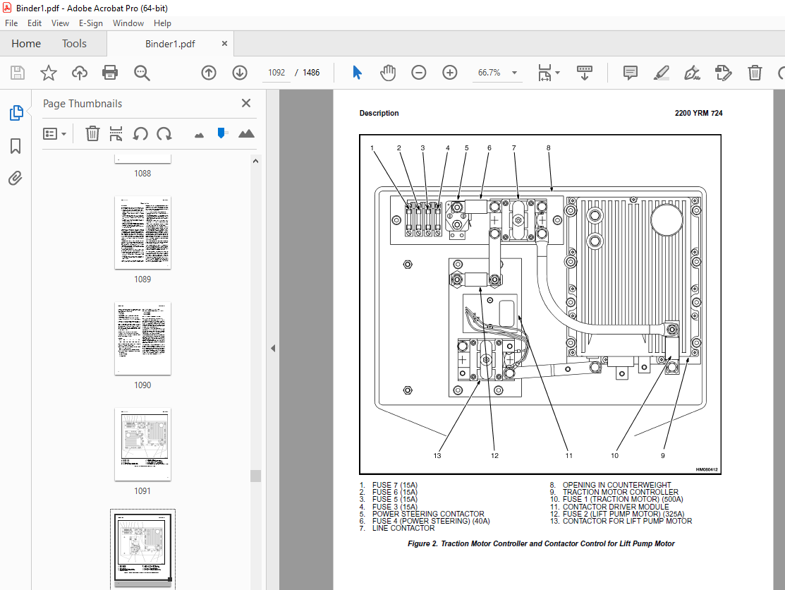
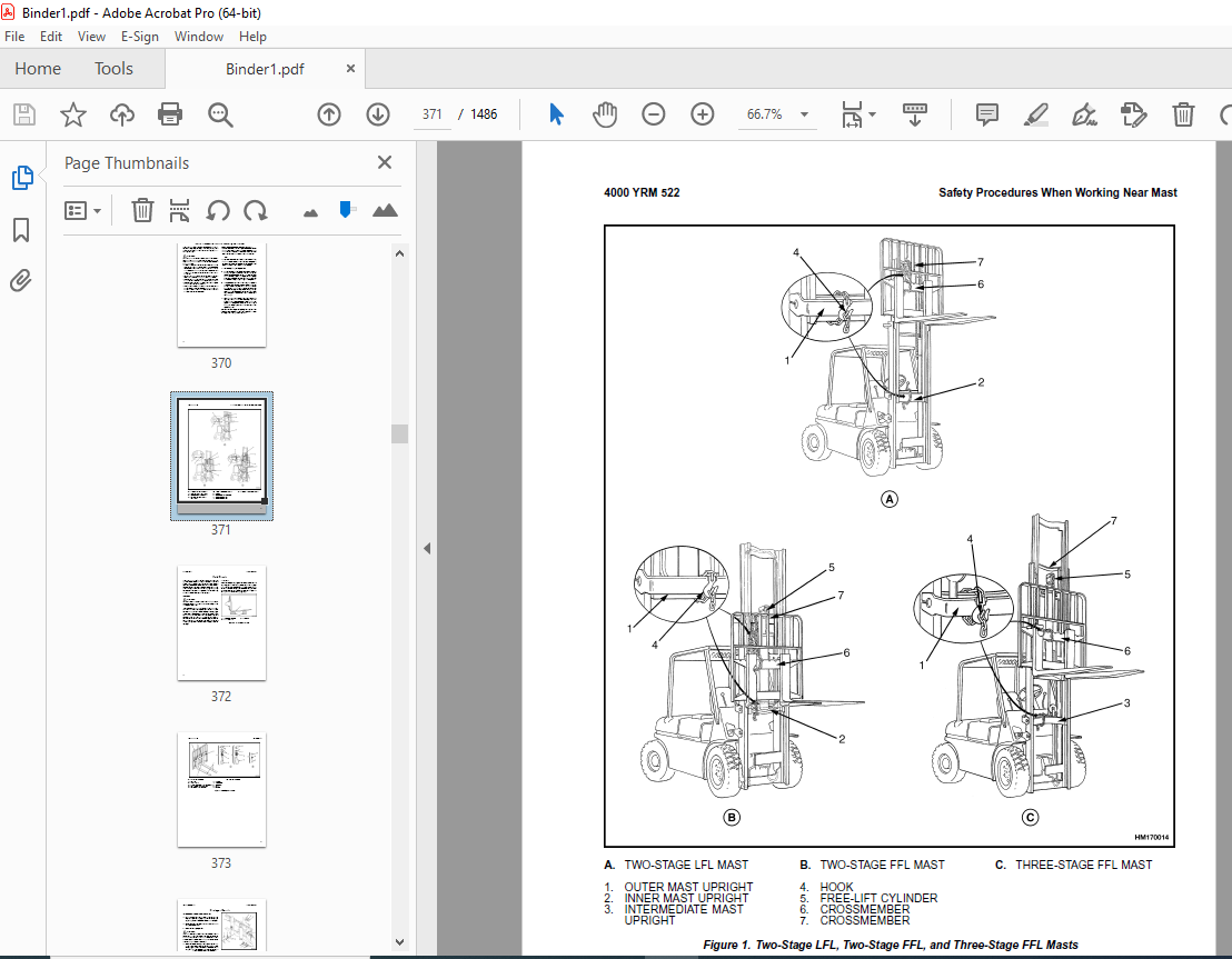
TABLE OF CONTENTS:
Yale Forklift A814 (ERP AF_BF) Service Manual – PDF DOWNLOAD
524150790-2100YRM0103-(03-2007)-UK-EN 227
toc 227
Tilt Cylinders 227
Safety Precautions Maintenance and Repair 228
General 231
Description 231
Tilt Cylinder Repair 231
Remove 231
Disassemble 231
Clean 231
Assemble 232
Tilt Cylinders With O-Ring or Single-Lip Seals 232
Tilt Cylinders 233
Install 234
Tilt Cylinder Leak Check 236
Tilt Cylinder Stroke and Mast Tilt Angle Adjustment 237
Torque Specifications 237
Piston Rod Nut 237
Retainer 237
Troubleshooting 238
tables 227
Table 1 Movement Rates (Maximum) for Tilt Cylinders 236
524150797-8000YRM0231-(02-2023)-UK-EN 243
General 249
Threaded Fasteners 249
Nomenclature, Threads 249
Strength Identification 250
Cotter (Split) Pins 251
Fastener Torque Tables 256
Conversion Table 258
524158040-2240YRM0001-(01-2023)-UK-EN 265
General 271
Battery Type 271
Lead-Acid Batteries 271
Lithium-Ion Batteries 272
Specific Gravity 272
Chemical Reaction in a Cell 272
Electrical Terms 274
Battery Selection 275
Battery Voltage 276
Battery as a Counterweight 276
Battery Ratings 276
Kilowatt-Hours 276
Battery Maintenance 277
Safety Procedures 277
Maintenance Records 277
New Battery 277
Cleaning Battery 278
Adding Water to Battery 280
Hydrometer 280
Battery Temperature 281
Charging Battery 282
Types of Battery Charges 283
Methods of Charging 284
Troubleshooting Charger 285
Knowing When Battery Is Fully Charged 285
Where to Charge Batteries 285
Equipment Needed 285
Battery Connectors 286
Battery Care 286
Troubleshooting 288
524158753-1600YRM0720-(11-2006)-UK-EN 293
toc 293
Steering Housing and Control Unit 293
Safety Precautions Maintenance and Repair 294
General 297
Description 297
Operation 298
Steering Wheel and Column Assembly Repair 299
Assembly Components, Remove 299
Steering Control Unit, Disassemble 304
Steering Control Unit, Clean 304
Steering Control Unit, Assemble 304
Assembly Components, Install 306
System Air Removal 308
Troubleshooting 308
524158757-2200YRM0514-(01-2004)-UK-EN 313
toc 313
Instrument Cluster 313
Safety Precautions Maintenance and Repair 314
General 317
Description 317
Instrument Cluster Display Panel, Internal Combustion Lift Truck 317
Instrument Cluster Display Panel, Electric Lift Truck Models 324
Optional Basic Display Panel 324
Features of the Optional Basic Display Panel 324
Description of Features on the Optional Basic Display Panel 324
Standard Display Panel 325
Features of the Standard Display Panel 325
Description of Features on the Standard Display Panel 325
Premium Display Panel 326
Features on the Premium Display Panel 326
Description of Features on the Premium Display Panel 327
Curtis 1215 Display Panel 329
Description and Features 329
Operation 330
Cluster-Type Display Panel (Internal Combustion) Replacement 331
Remove 331
Install 331
Cluster Display Panel (Electric Lift Truck) Replacement 334
Curtis 1215 Display Panel Replacement 339
Remove 339
Install 339
tables 313
Table 1 Instrument Cluster, Internal Combustion 318
524158890-4000YRM0521-(03-2006)-UK-EN 343
toc 343
Mast 343
Safety Precautions Maintenance and Repair 344
General 347
Description and Operation 347
Carriages 347
Mast Mounts 349
Two-Stage Mast, Limited Free-Lift (LFL) 350
Description and Operation 350
Two-Stage Mast, Full Free-Lift (FFL) 352
Description and Operation 352
Three-Stage Mast, Full Free-Lift (FFL) 354
Description and Operation 354
Four-Stage Mast 356
Description and Operation 356
Cylinder Cushion During Lifting Sequence 360
Cylinder Cushion During Lowering Sequence 361
524158891-4000YRM0522-(07-2010)-UK-EN 365
toc 365
Mast 365
Safety Precautions Maintenance and Repair 366
General 369
Safety Procedures When Working Near Mast 370
Fork Repair 372
Remove 372
Install 372
Carriages Repair 374
Standard Carriage, Remove 374
Hang-On Sideshift Carriage, Remove 375
Standard Carriage and Hang-On Sideshift Carriage, Repair 376
Standard Carriage, Install 377
Hang-On Sideshift Carriage, Install 378
Integral Sideshift Carriage 378
Remove 378
Clean and Inspect 382
Repair 383
Install 384
Mast Repair 385
Remove 385
Two-Stage LFL and Two-Stage FFL Masts, Disassemble 387
Three-Stage FFL Mast 395
Disassemble 395
Mast and Chains, Clean and Inspect 398
Two-Stage LFL and Two-Stage FFL Mast, Assemble 399
Three-Stage FFL Mast, Assemble 400
Install 401
Lift Cylinders Repair 403
Main Lift Cylinders, Remove 403
Free-Lift Cylinder, Remove 403
Cylinders, Disassemble 404
Two-Stage Full Free-Lift Mast, Right-Hand Main Lift Cylinder 404
Two-Stage Full Free-Lift Mast, Left-Hand Main Lift Cylinder 406
Two-Stage Limited Free-Lift Mast and Three-Stage Full Free-Lift 406
Two-Stage Limited Free-Lift Mast and Three-Stage Full Free-Lift 407
Two-Stage Full Free-Lift Mast and Three-Stage Full Free-Lift Mas 408
Clean and Inspect 409
Cylinders, Assemble 409
Two-Stage Full Free-Lift Mast, Right-Hand Main Lift Cylinder 409
Two-Stage Full Free-Lift Mast, Left-Hand Main Lift Cylinder 410
Two-Stage Limited Free-Lift Mast and Three-Stage Full Free-Lift 411
Two-Stage Limited Free-Lift Mast and Three-Stage Full Free-Lift 411
Two-Stage Full Free-Lift Mast and Three-Stage Full Free-Lift Mas 412
Main Lift Cylinders, Install 413
Free-Lift Cylinder, Install 413
Header Hose Arrangements 414
Two-Stage LFL Mast, New Hose Install 414
Two-Stage LFL Mast, Adjust Hoses After Installation 419
Two-Stage FFL Mast, New Hose Install 419
Two-Stage FFL Mast, Adjust Hoses After Installation 427
Three-Stage FFL Mast, New Hose Install 427
Three-Stage FFL Mast, Adjust Hoses After Installation 438
Header Hose Arrangement 439
Two-Stage LFL Mast, New Hose Install 439
Two-Stage LFL Mast, Adjust Hoses After Installation 444
Two-Stage FFL Mast, New Hose Install 444
Two-Stage FFL Mast, Adjust Hoses After Installation 450
Three-Stage FFL Mast, New Hose Install 450
Three-Stage FFL Mast, Adjust Hoses After Install 459
Lift and Tilt System Leak Check 460
Lift Cylinders Leak Check 460
Tilt Cylinders Leak Check 460
Tilt Cylinders Adjustment 461
Lift Chains Adjustment 463
Mast Adjustment 465
Carriage Adjustment 467
Troubleshooting 468
tables 365
Table 1 Hook-Type Carriage Chain Adjustment 463
Table 2 Pin-Type Carriage Chain Adjustment 464
524166836-1600YRM0485-(07-2003)-UK-EN 471
toc 471
Steering System for Electric Lift Trucks 471
Safety Precautions Maintenance and Repair 472
General 475
Description 477
Steering Wheel and Column Assembly Repair 478
Assembly Components, Remove 478
Assembly Components, Install 482
Power Steering Motor and Pump 483
Description 483
Remove and Disassemble, Models ERC 20-30AGF (ERC040-065RF/ZF, RG 484
Remove and Disassemble, Models ERC35-55HG (ERC70-120HD, ERC70-12 485
Remove and Disassemble, Models ERP20-30ALF 488
Remove and Disassemble, Models ERC/P16-20AAF (ERC040-065AF, AG/B 488
Assemble and Install, All Models With A Vertical Mount Except ER 489
Assemble and Install, Models ERP20-30ALF 489
Assemble and Install, Models ERC/P16-20AAF (ERC030-040AF, AG/BG) 490
Power Steering Pump, Repair 490
Seal, Replace 491
Hydraulic Steering Motor 492
Steering System Air Removal 492
Steering Pressure Check 492
Optical Encoder and Activator Circuits Check 493
Troubleshooting 495
524166840-2200YRM0560-(07-2005)-UK-EN 499
toc 499
Electrical System 499
Safety Precautions Maintenance and Repair 500
General 505
Description 506
ZX Series Display Panels 506
Optional Basic Display Panel 506
Features of the Optional Basic Display Panel 506
Description of Features on the Optional Basic Display Panel 506
Standard Display Panel 507
Features of the Standard Display Panel 507
Description of Features on the Standard Display Panel 507
Premium Display Panel 508
Features on the Premium Display Panel 508
Description of Features on the Premium Display Panel 509
Curtis 1215 Display Panel 511
Description and Features 511
Operation 511
SEM Display Panels – Features 512
Descriptions of Common Features 513
LED Symbol Indicators – SEM 513
LCD Screen 513
Battery Discharge Indicator (BDI) 513
Service Reminder 514
Status Codes 514
Hourmeter 514
Additional Features of Premium Display Panel 515
Descriptions of Additional Features 515
LCD Screen 515
Operator Passwords 515
Daily Checklist and Service Items 515
Performance Modes 515
Status Code Lists 516
Adjustment of BDI 516
SEM Display Panel Indicators 516
All Indicator Symbols 516
Hourmeter Indicator Symbol 516
Wrench Symbol 516
Battery Symbol 516
Battery Discharge Indicator (BDI) 516
Brake Fluid Too Low Symbol 516
Parking Brake Symbol 516
Fasten Seat Belt Symbol 517
LCD Screen (Standard Display Panel) 517
Additional Components of Premium Display Panel 517
Alpha Numerical Screen 517
STAR Push Button 517
Push Buttons ##1 Through ##5 – SEM 517
Other Control Components 517
Display Panel Components – ZX, and Curtis Replacement 518
ZX Panel Replacement 518
Curtis 1215 Display Panel Replacement 523
Remove 523
Install 523
SEM Display Panel Replacement 524
Motor Controller (SR or SP) Replacement 524
Remove 524
Install 524
Control Components Replacement 526
Start Switch, Replace 526
Brake Light Switch, Replace 527
Seat Switch, Replace 527
External Seat Switch, Adjust 528
Switch for Optional Seat Brake, Replace 529
Parking Brake Switch, Replace 529
Direction Switches Foot Directional Control Replace 530
Direction Control Switches (Steering Column), Replace 531
Direction Control Switches, ERC070-120HG (Steering Column), Repl 532
Brake Fluid Switch, Replace 532
Brush Wear and Overtemperature Sensors 532
Rocker Switches for Lights 533
Accelerator Position Sensor, Replace 533
On-Demand Steering Components 535
Lights, Converter, Relay, and Reverse Alarm 537
Incandescent Brake, Tail, and Reverse Light Assembly, Replace 537
LED Brake, Tail, and Reverse Light Assembly, Replace 539
Remove 539
Install 539
Flashing Light Assembly, Replace 539
Front, Rear Driving Light, or Spot Light Assemblies, Replace 541
Operator Compartment Light Assembly, Replace 541
Converter, Replace 542
Relay, Replace 542
Reverse Alarm, Replace 542
Horn and Horn Button 542
Horn Switch and Cover 543
Hydraulic Pump Switches 543
Control and Power Fuses Check 544
ZX Motor Controllers 544
SEM Motor Controllers 544
SEM Controller Field Diagnostic Procedure 549
Armature FET Test 549
Field FET Test 549
Brush Wear and Overtemperature Sensors Check – ZX Motor Controll 553
Thermal Sensors – SEM Motor Controllers Check 554
Start Switch Adjustment 555
Accelerator Potentiometer and Start Switch, ERC070-120HG Lift Tr 556
ERC070-120HG 556
Direction Switches Foot Directional Control Pedal 557
Brake Light Switch Adjustment 558
Seat Switch Check 559
Optional Seat Brake Switch Adjustment 559
Parking Brake Switch Adjustment 560
Direction Switches Check 560
Foot Directional Control Pedal 560
Steering Column 561
Hydraulic Pump Switch Adjustment 561
Foot Directional Control or Accelerator Pedal Adjustment 561
Accelerator Position Sensor Adjustment 562
524166844-2200YRM0942-(08-2007)-UK-EN 567
toc 567
Display Panel for SEM Controls 567
Safety Precautions Maintenance and Repair 568
General 571
SEM Display Panel Features 571
Descriptions of Common Features 571
LED Symbol Indicators 571
LCD Screen 571
Battery Discharge Indicator (BDI) 572
Service Reminder 572
Status Codes 572
Hourmeter 572
Additional Features of Premium Display Panel 572
Descriptions of Additional Features (Available With Premium Disp 572
LCD Screen 572
Operator Passwords 573
Daily Check List and Service Items 573
Performance Modes 573
Status Code Lists 573
Adjustment of BDI 573
SEM Display Panel Indicators 574
All Indicator Symbols 574
Hourmeter Indicator Symbol 574
Wrench Indicator Symbol 574
Battery Indicator Symbol 574
Battery State-of-Charge (BDI) 574
Brake Fluid Too Low Symbol 575
Parking Brake Symbol 575
Fasten Seat Belt Symbol 575
LCD Screen (Standard Display Panel) 576
Additional Components of Premium Display Panel 576
Alphanumeric Screen 576
STAR Push Button 576
Push Buttons 1 Through 5 576
Adjustments With a Computer 576
Computer System 576
Connect PC to SEM Display Panel 577
ITW Switches Windows Software Program (for SEM Display Panel) 578
Description 578
Getting Help 578
Hardware and Software Requirements 578
Install 578
How to Start ITW Switches Program 578
Menus 582
Sample Sessions 591
Replacement 613
SEM Display Panel 613
Remove and Replace 613
tables 567
Table 1 Adapter Pins (DB25F to DB9) 577
524167640-2200YRM0947-(08-2007)-UK-EN 619
toc 619
Troubleshooting and Adjustments With a Computer 619
Safety Precautions Maintenance and Repair 620
Computer System 623
Connect a PC to a Control Card 624
Installation 625
SMARTSET™ Windows Software Program 625
How to Start the Program 625
DEMO Mode 626
Selecting the Communications Port 628
Verification of Controller and Lift Truck 629
Select Lift Truck Series 631
Controller Card Register Parameter List 632
How to Change a Parameter 633
How to Save a Changed Parameter File 634
How to Load a Saved Parameter File 636
How to Show and Remove Saved Parameter Files 636
How to Return to Factory Default Settings 637
How to Save Changes to Control Card 638
How to View Status Codes 639
Saving Status Codes 640
How to Show and Remove Saved Status Code Files 641
Closing and Clearing Status Code List 642
How to View Saved Register Data and Saved Status Data 643
How to Save Register Data and Status Code Data In RTF and TXT 645
GE Sentry™ Software Program 646
Installation 646
Description 646
How to Start GE SENTRY Program 646
How to Reset MIN and MAX Display 651
Graphing Mode 652
How to Exit GE SENTRY Program 653
tables 619
Table 1 Cable Connections – Computer to Control 623
Table 2 Adapter Pins (DB25F to DB9) 624
Table 3 Plug-Z Connection 625
524179936-0100YRM0617-(03-2006)-UK-EN 657
toc 657
Frame 657
Safety Precautions Maintenance and Repair 658
General 661
Description 661
Main Frame 661
Other Frame Weldments 671
Overhead Guard 672
Overhead Guard Replacement 677
Remove 677
Install 678
Battery and Operator Restraint System, Hood and Seat Brake, and 678
Battery Restraint System 678
Hood and Seat Brake 680
Hood With E-Hydraulics 681
Operator Restraint System and Seat Assembly 682
Automatic Locking Retractor (ALR) 682
Emergency Locking Retractor (ELR) 682
Counterweight Replacement 683
Remove 683
Install 685
Traction Motor Replacement 686
Remove 686
Install 688
Hydraulic Tank Repair 689
Inspect 689
Clean 690
Steam Method 690
Chemical Solution Method 690
Additional Preparations for Repair 691
Small Leaks, Repair 691
Large Leaks, Repair 691
Preparations for Usage After Repair 691
Painting Instructions 691
Safety Label Replacement 693
Battery Specifications 695
tables 657
Table 1 Counterweights 684
524179939-1400YRM0618-(03-2006)-UK-EN 699
toc 699
Drive Axle, Speed Reducer, and Differential 699
Safety Precautions Maintenance and Repair 700
General 703
Description 703
Drive Unit Assembly Repair 703
Remove Complete Drive Unit Assembly as a Unit 703
Traction Motor, Remove 704
Drive Unit and Speed Reducer, Remove 706
Drive Axle, Disassemble 707
Differential and Speed Reducer, Disassemble 707
Clean 710
Inspect 710
Assembly of Drive Unit 710
Find Correct Shim Set for Hypoid Gear 710
Pinion, Assemble and Install 711
Differential and Ring Gear, Assemble and Install 712
Input Gear for Speed Reducer, Assemble 716
Drive Axle and Hub Assembly, Assemble 717
Installation of Drive Unit 718
Drive Unit, Install 718
Traction Motor, Install 719
Torque Specifications 720
Troubleshooting 721
tables 699
Table 1 Shims Adjustment for Pinion 711
Table 2 Ring and Pinion Tooth Contact Adjustment 715
524179940-1600YRM0619-(03-2006)-UK-EN 725
toc 725
Steering Axle 725
Safety Precautions Maintenance and Repair 726
General 729
Description 729
Steering Axle Assembly Repair 730
Remove 730
Install 730
Wheels and Hubs Repair 731
Remove and Disassemble 731
Clean 731
Assemble and Install 731
Spindles, Bearings, and Links Repair 735
Remove and Disassemble; Lift Truck Models ERC/P16-20AAF (A814/B8 735
Clean 735
Assemble and Install; Lift Truck Models ERC/P16-20AAF (A814/B814 735
Remove and Disassemble; Lift Truck Models ERC030-040AF and ERC03 737
Clean 737
Inspect 737
Assemble and Install; Lift Truck Models ERC030-040AF and ERC030- 737
Steering Cylinder Repair 739
Remove and Disassemble 739
Clean and Inspect 739
Assemble and Install 739
Torque Specifications 740
Troubleshooting 741
524179941-1600YRM0512-(07-2003)-UK-EN 745
toc 745
Steering Housing and Control Unit 745
Safety Precautions Maintenance and Repair 746
General 749
Description 749
Operation 750
Steering Wheel and Column Assembly Repair 751
Steering Column Assembly, Remove 751
Steering Control Unit 756
Disassemble 756
Clean 759
Assemble 760
Install 767
Steering Column Assembly, Install 769
System Air Removal 770
Remove 770
Troubleshooting 770
524179944-1800YRM0620-(03-2008)-UK-EN 775
toc 775
Brake System 775
Safety Precautions Maintenance and Repair 776
General 779
Description and Operation 779
Service Brakes 779
Master Cylinder 779
Parking Brake 781
Service Brakes Repair 781
Remove and Disassemble 781
Clean 784
Inspect 784
Assemble and Install 785
Master Cylinder Repair 788
Remove 788
Disassemble 789
Clean and Inspect 791
Assemble 791
Install 794
Parking Brake Repair 794
Remove and Dissemble 794
Assemble and Install 794
Parking Brake Switch Replacement 798
Brake System Air Removal 798
Service Brakes Adjustment 799
Brake Pedal Adjustment 799
Master Cylinder Adjustment 800
Parking Brake Adjustment 800
Parking Brake Switch Adjustment 800
Parking Brake Not Applied Switch Test 800
Seat Brake Assembly 800
Seat Brake, Adjust – Lift Truck Models ERC/P16-20AAF (ERC030-040 800
Brake Switch, Adjust – Lift Truck Models ERC/P16-20AAF (ERC030-0 801
Electric Seat Brake Without Handle, Adjust for Lift Truck Model 802
Electric Seat Brake With Handle for Lift Truck Model ERC/P16-20A 803
Remove 803
Clean 803
Inspect 803
Install 805
Adjustments 805
Solenoid Adjustment 805
Traction cutoff Switch Adjustment 805
Cable Adjustment 806
Torque Specifications 808
Troubleshooting 808
524179945-1900YRM0559-(04-2009)-UK-EN 815
toc 815
Hydraulic System 815
Safety Precautions Maintenance and Repair 816
General 819
Description 819
Hydraulic System 819
Operation 827
Hydraulic System 827
Hydraulic Gear Pump 833
Steering Pump 833
Hydraulic Tank Repair 841
Tank, Remove [ERC/P16-20AAF (ERC030-040AF, AG/BG) (A814); ERC/P1 841
Tank, Remove [ERP20-30ALF (B216) and ERP20-30ALF (ERP040-060DH) 843
Tank, Remove [ERP20-32ALF (ERP040-065DH) (E216)] 844
Hydraulic Tank [ERC35-55HG (ERC70-120HH) (B839/C839)] 844
Inspect 845
Small Leaks, Repair 846
Large Leaks, Repair 846
Clean 846
Steam Method 846
Chemical Solution Method 847
Additional Methods for Tank Repair 847
Tank, Install [ERC/P16-20AAF (ERC030-040AF, AG/BG) (A814); ERC/P 847
Tank, Install [ERP20-30ALF (B216) and ERP20-30ALF (ERP040-060DH) 848
Tank, Install [ERP20-32ALF (ERP040-065DH) (E216)] 848
Filter Replacement 849
All Lift Trucks Except [ERC35-55HG (ERC70-120HH) (B839/C839); ER 849
Remove 849
Install 850
Lift Truck Models [ERC35-55HG (ERC70-120HH) (B839/C839)] 850
Remove 850
Install 850
Lift truck Models [ERC20-32AGF (ERC040-065GH) (A908) and ERC/P16 851
Remove 851
Install 851
Lift Truck Models [ERP20-32ALF (ERP040-065DH) (E216)] 853
Remove 853
Install 853
Hydraulic Pump Repair 856
Hydraulic Pump, Remove [ERC/P16-20AAF (ERC030-040AF, AG/BG) (A81 856
Hydraulic Pump, Disassemble ERC/P16-20AAF (ERC030-040AF, AG/BG) 856
Inspect 858
Clean 858
Pump Seal Replace and Pump Assemble 858
Assemble Pump on Motor 858
Hydraulic Pump and Motor, Install [ERC/P16-20AAF (ERC030-040AF, 860
Hydraulic Pump, Remove [ERP20-30ALF (B216); ERP20-30ALF (ERP040- 861
Hydraulic Pump, Disassemble [ERC35-55HG (ERC70-120HH) (B839/C839 862
Hydraulic Pump, Inspect [ERC35-55HG (ERC70-120HH) (B839/C839) an 864
Hydraulic Pump, Clean [ERC35-55HG (ERC70-120HH) (B839/C839) and 864
Hydraulic Pump, Assemble [ERC35-55HG (ERC70-120HH) (B839/C839) a 864
Hydraulic Pump and Motor, Install [ERP20-30ALF (B216); ERP20-30A 864
Main Control Valve Repair 866
Steering Pump Repair 866
Pump, Remove and Disassemble [ERC/P16-20AAF (ERC030-040AF, ERC03 866
Pump, Remove and Disassemble [ERP20-30ALF (B216); ERP20-30ALF (E 868
Pump, Assemble and Install 870
Steering Control Unit Replacement 871
Remove 871
Install 871
Steering Cylinder Repair 877
Main Control Valve Check and Adjust 877
Steering Relief Valve Check and Adjust 878
Specifications 878
Relief Valve Pressures* 878
Hydraulic Tank Capacity (dipstick full mark) 879
Hydraulic Pump Capacities – All Models Except ERC35-55HG (ERC70- 879
Hydraulic Pump Capacities – Models ERC35-55HG (ERC70-120HH) (B83 879
Troubleshooting 879
Steering 879
Steering Housing and Steering Control Unit 880
Hydraulic System 881
524179946-2000YRM0562-(02-2009)-UK-EN 887
toc 887
Manual hydraulic Control Valve 887
Safety Precautions Maintenance and Repair 888
General 891
Description 891
Operation 894
ERC/P16-20AAF (ERC030-040AF, AG/BG) (A814); ERC/P16-20AAF (ERC03 894
ERP20-30ALF (B216), ERP20-30ALF (ERP040-060DH) (D216) and ERP20- 894
Lift Section 896
Tilt Section 896
Tilt Backward 896
Tilt Forward 896
Relief Valve 898
Main Control Valve Repair 899
Main Control Valve Without OPS Solenoid 899
Remove 899
Disassemble 899
Clean and Inspect 903
Assemble 903
Install [ERC/P16-20AAF (ERC030-040AF, AG/BG) (A814); ERC/P16-20A 904
Install [ERP20-30ALF (B216), ERP20-30ALF (ERP040-060DH) (D216) a 904
Main Control Valve With OPS Solenoid 905
Remove 905
Disassemble 905
Clean and Inspect 907
Relief Valve Repair 909
Assemble 910
Install 911
Control Lever Linkage Repair 911
Remove [ERC/P16-20AAF (ERC030-040AF, AG/BG) (A814),ERC/P16-20AAF 911
Disassemble [ERC/P16-20AAF (ERC030-040AF, AG/BG) (A814),ERC/P16- 911
Assemble and Install [ERC/P16-20AAF (ERC030-040AF, AG/BG) (A814) 913
Control Valve Linkage Repair 913
Remove and Disassemble [ERC/P16-20AAF (ERC030-040AF, AG/BG) (A81 913
Assemble and Install [ERC/P16-20AAF (ERC030-040AF, AG/BG) (A814) 914
Control Lever Linkage Repair 914
Remove [ERP20-30ALF (B216), ERP20-30ALF (ERP040-060DH) (D216) an 914
Disassemble [ERP20-30ALF (B216), ERP20-30ALF (ERP040-060DH) (D21 916
Assemble and Install [ERP20-30ALF (B216), ERP20-30ALF (ERP040-06 916
Pressure Relief Valve Check and Adjustment 917
Primary Relief Valve 917
Secondary Relief Valve 918
Troubleshooting 919
524179947-2200YRM0557-(07-2003)-UK-EN 923
toc 923
EV-100ZX™ SCR Motor Controller 923
Safety Precautions Maintenance and Repair 924
General 929
Model Number Data For EV-100ZX Controller 930
Register Parameters 944
General 944
Function Numbers 944
Control Card, Checks and Adjustments 944
Handset 945
How to Check and Adjust Registers 945
How to Scroll through Fault Codes and Clear Them 945
Checks and Adjustments on Workbench 946
When Handset Is Connected to Control Card Installed In Lift Truc 947
Function Numbers 1 through 15 948
Function Numbers 16 through 30 948
Function Numbers 48 through 62 948
Control Cards 949
Function Number Descriptions 949
Traction Control Cards (Label Letters – ZH and ZY) 949
Function Number 1 STORED STATUS CODE 949
Function Number 2 CREEP SPEED 949
Function Number 3 CONTROLLED ACCELERATION AND 1A TIME 949
Function Number 4 CURRENT LIMIT 950
Function Number 5 PLUGGING DISTANCE (CURRENT) 950
Function Number 6 1A DROP OUT CURRENT 950
Function Number 7 FIELD WEAKENING PICK UP 950
Function Number 8 FIELD WEAKENING DROP OUT 950
Function Number 9 REGENERATIVE BRAKING CURRENT LIMIT 950
Function Number 10 REGENERATIVE BRAKING START 951
Function Number 13 SPEED LIMIT 3 (SL3) 951
Function Number 14 INTERNAL RESISTANCE COMPENSATION 951
Function Number 15 BATTERY VOLTS 952
Function Numbers GREATER THAN 15 952
Function Number 16 PEDAL POSITION PLUG 952
Function Number 17 CARD TYPE SELECTION 952
Function Number 18 STEERING PUMP TIME DELAY 952
Function Number 19 MAINTENANCE ALERT (Tens/Units) 953
Function Number 20 MAINTENANCE ALERT (Thousands/Hundreds) 953
Function Number 21 MAINTENANCE SPEED LIMIT 953
Function Numbers 22 Through 28 TEMPORARY DATA REGISTERS 953
Function Number 29 HOURMETER (Tens/Units) 953
Function Number 30 HOURMETER (Thousands/Hundreds) 953
Function Number 48 Through 62 SET LIFT TRUCK PERFORMANCE 953
Function Number 48 CONTROLLED ACCELERATION AND 1A TIME 954
Function Number 49 FIELD WEAKENING PICK UP 954
Function Number 50 SPEED LIMIT 1 954
Function Number 52 CONTROLLED ACCELERATION AND 1A TIME 954
Function Number 53 FIELD WEAKENING PICK UP 954
Function Number 54 SPEED LIMIT 1 955
Function Number 56 CONTROLLED ACCELERATION AND 1A TIME 955
Function Number 57 FIELD WEAKENING PICK UP 955
Function Number 58 SPEED LIMIT 1 955
Function Number 60 CONTROLLED ACCELERATION AND 1A TIME 955
Function Number 61 FIELD WEAKENING PICK UP 955
Pump Control Card (Label Letter ZP) 955
Function Number 1 STORED STATUS CODE 956
Function Number 2 INTERNAL RESISTANCE COMPENSATION START 956
Function Number 3 CONTROLLED ACCELERATION 956
Function Number 4 CURRENT LIMIT 956
Function Number 7 CONTROLLED ACCELERATION COMPENSATION 956
Function Number 11 SPEED LIMIT 1 (SL1) (Slow Speed) – Tilt and S 956
Function Number 12 SPEED LIMIT 2 (SL2) (Medium Speed) – Slow Lif 956
Function Number 13 SPEED LIMIT 3 (SL3) 956
Function Number 14 SPEED LIMIT 4 (SL4) Fast Lift 957
Function Numbers Greater Than 15 957
Function Number 16 INTERNAL RESISTANCE COMPENSATION 957
Function Number 17 CARD TYPE SELECTION 957
Function Numbers 18 through 28 TEMPORARY DATA REGISTERS 957
Function Number 29 HOURMETER (Tens/Units) 957
Function Number 30 HOURMETER (Thousands/Hundreds) 957
Function Number 48 CONTROLLED ACCELERATION 958
Function Number 49 SPEED LIMIT 2 958
Function Number 50 SPEED LIMIT 3 958
Function Number 52 CONTROLLED ACCELERATION 958
Function Number 53 SPEED LIMIT 2 958
Function Number 54 SPEED LIMIT 3 958
Function Number 56 CONTROLLED ACCELERATION 958
Function Number 57 SPEED LIMIT 2 958
Function Number 58 SPEED LIMIT 3 958
Function Number 60 CONTROLLED ACCELERATION 959
Function Number 61 SPEED LIMIT 2 959
Function Number 62 SPEED LIMIT 3 959
Register Parameters 959
Troubleshooting 959
General 959
Status Codes 960
Register Maps 962
Status Code Charts 973
EV-100ZX SCR Motor Controller Repair 1014
Fuses 1014
SCR, Check 1014
SCR Assembly 1016
Thermal Protector 1016
SCR 1 Assembly, Replace 1016
OFF Circuit for SCR 1 1017
Reactor Assembly, Check 1017
Suppressors for SCR 2 and SCR 5, Check 1017
SCR 2 and SCR 5, Check 1017
SCR 2 and SCR 5, Replace 1018
Capacitor C1, Check 1018
Diodes D3 and D4 1018
Diodes D3 and D4, Check 1018
Diodes D3 and D4, Replace 1018
Motor Current Sensor 1018
Contactors 1019
Contactor, Repair 1019
Control Card 1021
Control Card Plugs 1022
Brush Wear Indicators 1022
Theory of Operation 1023
Electronic Speed Controls 1023
Silicon Controlled Rectifier (SCR) 1024
Motor Circuit That Operates With Pulses 1025
Traction Circuit 1026
Hydraulic Pump Motor 1026
SCR 1 OFF Circuit 1026
SCR 1 OFF Operation 1027
Induction Current from Motor 1029
Control Cards 1030
Pulse Monitor Trip (PMT) (Traction Circuit Only) 1030
SRO Circuit (Traction Circuit Only) 1030
Sequence of Operation 1031
Control Card Adjustments (Traction Circuit) 1031
Accelerator Control 1035
SCR Control (Hydraulic Pump Motor) 1035
Contactors 1035
Circuit Protection 1036
Traction Circuit Fuse 1036
Current Limit 1036
Thermal Protection 1036
Suppressors 1037
Truck Management Module (TMM1) 1037
Display Panels 1038
Display Panel 1038
Optional Basic Display Panel 1038
Features of the Optional Basic Display Panel 1038
Description of Features on the Optional Basic Display Panel 1039
Standard Display Panel 1039
Features of the Standard Display Panel 1039
Description of Features on the Standard Display Panel 1040
Premium Display Panel 1041
Features on the Premium Display Panel 1041
Description of Features on the Premium Display Panel 1042
Curtis 1215 Display Panel 1044
Description and Features 1044
Operation 1045
tables 923
Table 1 Terminal and Plug Wire Connections for Control Card ZY, 936
Table 2 Terminal and Plug Wire Connections for Control Card ZH, 938
Table 3 Terminal and Plug Wire Connections for Control Card ZH, 940
Table 4 Terminal and Plug Wire Connections for Controller with 942
Table 5 Status Codes List 961
Table 6 Register Map for Control Cards ZH and ZY (Traction) 963
Table 7 Register Map for Control Card ZP (Hydraulic Pump) 968
Table 8 Terminal and Plug Wire Connections for TMM1 Module 1038
524179950-2200YRM0624-(07-2003)-UK-EN 1049
toc 1049
EV-100ZX TM SCR MOTOR CONTROLLER 1049
Safety Precautions Maintenance and Repair 1050
Register Parameters 1053
General 1053
Function Numbers 1054
Control Card Checks and Adjustments 1054
Register Parameter Tables 1055
tables 1049
Table 1 EV-100ZX Parameters [Heavy Duty Motor ( Yale Part Numbe 1055
Table 2 EV-100ZX Parameters [Heavy Duty Motor ( Yale Part Numbe 1059
Table 3 EV-100ZX Parameters [Standard Motor ( Yale Part Number 1063
Table 4 EV-100ZX Parameters [Standard Motor ( Yale Part Number 1067
Table 5 EV-100ZX Parameters [Standard Motor ( Yale Part Number 1071
Table 6 EV-100ZX Parameters (Standard System) (Hydraulic Pump C 1075
Table 7 EV-100ZX Parameters (Low Energy System) (Hydraulic Pump 1078
524179951-2200YRM0724-(04-2005)-UK-EN 1083
toc 1083
SR/SP Transistor Motor Controllers 1083
Safety Precautions Maintenance and Repair 1084
Description 1089
General 1089
Model Number Data for SR/SP Transistor Motor Controllers 1090
Motor Controller Checks and Adjustments 1093
Checks and Adjustments Using Handset 1093
General 1093
Connect Handset 1094
Start Sequence 1094
Check or Delete Stored Status Codes 1095
Returning Lift Truck to Normal Operation 1097
Workbench Checks and Adjustments 1097
How to Check and Adjust Registers 1099
Function Parameters Adjustments 1099
General 1099
Function Numbers 1100
When Handset is Connected to Motor Controller in Lift Truck 1100
Function Numbers 1 through 15 1100
Function Numbers 16 through 30 1100
Function Numbers 48 through 63 1101
Function Number Descriptions 1102
Traction Motor Controller (Label Letter – SR) 1102
Function Number 01 AUTO REGEN ENABLE SPEED 1102
Function Number 02 CREEP SPEED 1102
Function Number 03 CONTROLLED ACCELERATION 1102
Function Number 04 ARMATURE CURRENT LIMIT 1102
Function Number 05 REGEN RAMP RATE 1103
Function Number 06 FIELD WEAKENING (FW) RATIO 1103
Function Number 07 MINIMUM FIELD CURRENT 1103
Function Number 08 MAXIMUM FIELD CURRENT 1103
Function Number 09 REGENERATIVE BRAKING CURRENT LIMIT (C/L) 1103
Function Number 10 FIELD CURRENT FOR REGENERATIVE BRAKING 1103
Function Number 12 MAXIMUM ARMATURE % ON TIME (Travel Speed Limi 1103
Function Number 13 SPEED LIMIT 3 1104
Function Number 14 INTERNAL RESISTANCE COMPENSATION 1104
Function Number 15 BATTERY VOLTAGE SELECTION 1104
Function Number 16 STALL TRIP POINT % ON TIME 1105
Function Number 17 CONTROL TYPE SELECTION 1105
Function Number 18 STEERING PUMP TIME DELAY 1105
Function Number 19 MAINTENANCE CODE TENS AND UNITS 1106
Function Number 20 MAINTENANCE CODE THOUSANDS AND HUNDREDS 1106
Function Number 21 AUTO REGEN BRAKING CURRENT LIMIT 1106
Function Number 23 FOR SPECIAL FUNCTIONS 1106
Function Number 24 FIELD WEAKENING START 1106
Function Number 25 MONITOR 1106
Function Number 26 BASE RATIO 1106
Function Number 28 STORED STATUS CODE COUNT POINTER 1106
Functions with Premium Display Panel Only 1107
Function Number 48 MODE 1 – CONTROLLED ACCELERATION 1107
Function Number 49 MODE 1 FIELD WEAKENING (FW) START 1107
Function Number 50 MODE 1 – FIELD WEAKENING (FW) RATIO 1107
Function 51 MODE 1 – MAXIMUM ARMATURE % ON TIME (MODE 1 – TRAVEL 1108
Function 52 MODE 2 – CONTROLLED ACCELERATION 1108
Function Number 53 MODE 2 – FIELD WEAKENING (FW) START 1108
Function Number 54 MODE 2 – FIELD WEAKENING (FW) RATIO 1108
Function Number 55 MODE 2 – MAXIMUM ARMATURE % ON TIME (MODE 2 – 1108
Function Number 56 MODE 3 – CONTROLLED ACCELERATION 1108
Function Number 57 MODE 3 – FIELD WEAKENING (FW) START 1108
Function Number 58 MODE 3 – FIELD WEAKENING (FW) RATIO 1108
Function Number 59 MODE 3 – MAXIMUM ARMATURE % ON TIME (MODE 3 – 1109
Function Number 60 MODE 4 – CONTROLLED ACCELERATION 1109
Function Number 61 MODE 4 – FIELD WEAKENING (FW) START 1109
Function Number 62 MODE 4 – FIELD WEAKENING (FW) RATIO 1109
Function Number 63 MODE 4 – MAXIMUM ARMATURE % ON TIME (MODE 4 – 1109
Pump Motor Controller (Label Letter – SP) 1109
Function Number 01 STORED STATUS CODE 1109
Function Number 02 INTERNAL RESISTANCE COMPENSATION START 1110
Function Number 03 CONTROLLED ACCELERATION 1110
Function Number 04 CURRENT LIMIT 1110
Function Number 07 INTERNAL RESISTANCE COMPENSATION RATE 1110
Function Number 11 SPEED LIMIT 1 (SL1) (Slow Speed) – Tilt and S 1110
Function Number 12 SPEED LIMIT 2 (SL2) (Medium Speed) – Slow Lif 1110
Function Number 13 SPEED LIMIT 3 (SL3) Fast Lift 1110
Function Number 16 SPEED/TORQUE COMPENSATION 1111
Function Number 17 CONTROL TYPE SELECTION 1111
Function Numbers 18 through 27 TEMPORARY DATA REGISTERS 1111
Function Number 28 STORED STATUS CODE COUNT POINTER 1111
Functions with Premium Display Panel Only 1111
Function Number 48 MODE 1 – CONTROLLED ACCELERATION 1112
Function Number 49 MODE 1 – SPEED LIMIT 2 1112
Function Number 50 MODE 1 – SPEED LIMIT 3 1112
Function Number 52 MODE 2 – CONTROLLED ACCELERATION 1112
Function Number 53 MODE 2 – SPEED LIMIT 2 1112
Function Number 54 MODE 2 – SPEED LIMIT 3 1112
Function Number 56 MODE 3 – CONTROLLED ACCELERATION 1112
Function Number 57 MODE 3 – SPEED LIMIT 2 1112
Function Number 58 MODE 3 – SPEED LIMIT 3 1113
Function Number 60 MODE 4 – CONTROLLED ACCELERATION 1113
Function Number 61 MODE 4 – SPEED LIMIT 2 1113
Function Number 62 MODE 4 – SPEED LIMIT 3 1113
Troubleshooting 1117
General 1117
Status Codes 1118
SR (SEM) and SP Status Code Charts 1120
SR/SP Transistor Motor Controller Repair 1154
General 1154
General Maintenance Instructions 1154
Special Precautions 1157
Fuses 1157
Contactors 1158
Repair 1158
Contactor Driver Module 1160
Contactor Driver, Replace 1160
Motor Controller Plug 1160
Brush Wear Indicators 1165
Thermal Sensors 1165
Motor Controller, Replace 1165
Theory of Operation 1166
General 1166
SEM System Description 1166
SEM System Operation (SR Motor Controller) 1166
Reverse Circuit 1166
Performance and Efficiency 1168
Field Weakening 1168
Regenerative Braking 1168
SEM System Operation (SP Motor Controller) 1169
Creep Speed 1169
Controlled Acceleration 1169
Current Limit (CL) 1169
Braking 1169
Regenerative Braking to Zero Speed 1169
Pedal Position Braking 1170
Auto Braking 1170
Auxiliary Speed Control 1170
Field Weakening 1170
Speed Limits 1170
Ramp Operation 1170
Ramp Start 1170
Anti-rollback 1170
Steer Pump Contactor Time Delay 1170
Coil Drivers and Internal Coil Suppression 1170
System Protective Override 1170
Static Return to Off (SRO) 1170
Accelerator Volts Hold Off 1171
Pulse Monitor Trip (PMT) 1171
Thermal Protector (TP) 1171
Low Voltage 1171
SP Pump Motor Controllers 1171
Contactor Driver Module 1172
Diagnostics 1172
Systems Diagnostics 1172
Standard Status Codes 1172
Stored Status Codes 1172
Hourmeter Readings 1172
Maintenance Management Capability 1172
tables 1083
Table 1 List of Status Codes 1096
Table 2 Speed/Torque Compensation 1110
Table 3 Function Map for Motor Controllers SR (Traction) 1113
Table 4 Function Map for Motor Controller SP (Lift Pump Motor) 1116
Table 5 List of Status Codes 1118
Table 6 Large (P) Plug (23-Pin) Connections/Descriptions for Mo 1161
Table 7 Small Plug (12-Pin) Connections/Descriptions for Motor 1162
524179952-2200YRM0739-(04-2005)-UK-EN 1175
toc 1175
Transistor Motor Controllers 1175
Safety Precautions Maintenance and Repair 1176
General 1179
Function Numbers 1179
Motor Controller Checks and Adjustments 1180
Parameter Tables 1180
tables 1175
Table 1 SR (SEM) Register Parameters for Traction Motor Control 1180
Table 2 SR (SEM) Register Parameters for Traction Motor Control 1184
Table 3 SP Register Parameters for Pump Motor Controller – ERC/ 1187
Table 4 SR (SEM) Register Parameters for Traction Motor Control 1190
Table 5 SR (SEM) Register Parameters for Traction Motor Control 1194
Table 6 SR (SEM) Register Parameters for Traction Motor Control 1197
Table 7 SR (SEM) Register Parameters for Traction Motor Control 1201
Table 8 SP Register Parameters for Pump Motor Controller – ERC0 1204
Table 9 SP Register Parameters for Pump Motor Controller – ERC2 1207
Table 10 SR (SEM) Register Parameters for Traction Motor Contro 1211
Table 11 SR (SEM) Register Parameters for Traction Motor Contro 1214
Table 12 SR (SEM) Register Parameters for Traction Motor Contro 1217
Table 13 SP Register Parameters for Pump Motor Controller – ERP 1220
Table 14 SP Register Parameters for Pump Motor Controller – ERP 1223
524179953-4000YRM0563-(04-2005)-UK-EN 1229
toc 1229
Four-Stage Mast 1229
Safety Precautions Maintenance and Repair 1230
General 1233
Description 1233
Carriages 1233
Mast Mounts 1234
Mast 1234
Description 1234
Operation 1235
Forks Repair 1238
Remove 1238
Install 1238
Safety Procedures When Working Near Mast 1240
Carriage Repair 1242
Remove 1242
Standard Carriage 1242
Sideshift Carriage 1243
Repairs 1244
Install 1244
Standard Carriage 1244
Sideshift Carriage 1244
Mast Repair 1245
Remove 1245
Disassemble 1245
Clean and Inspect 1246
Assemble 1247
Install 1249
Lift Cylinders Repair 1252
Remove 1252
Main Lift Cylinders 1252
Free-Lift Cylinders 1252
Disassemble 1252
Assemble 1254
Install 1256
Main Lift Cylinder 1256
Free-Lift Cylinder 1257
Header Hose Arrangements 1258
Header Hoses, Install 1258
Lift and Tilt System Leaks Check 1265
Lift Cylinders Leaks Check 1265
Tilt Cylinders Leaks Check 1265
Tilt Cylinders Adjustment 1266
Lift Chain Adjustments 1267
Mast Adjustments 1268
Carriage Adjustments 1270
Troubleshooting 1271
tables 1229
Table 1 Standard Four-Stage Hose Dimensions 1264
Table 2 Hook type Carriage Chain Adjustment 1267
Table 3 Pin-Type Carriage Chain Adjustment 1268
524179955-8000YRM0622-(07-2003)-UK-EN 1275
toc 1275
Electrical Diagrams 1275
Safety Precautions Maintenance and Repair 1276
524179956-8000YRM0742-(06-2004)-UK-EN 1325
toc 1325
Electrical Diagrams 1325
Safety Precautions Maintenance and Repair 1326
524179957-8000YRM0552-(07-2003)-UK-EN 1389
toc 1389
Periodic Maintenance 1389
Safety Precautions Maintenance and Repair 1390
General 1395
Serial Number Data 1395
How to Move Disabled Lift Truck 1395
How to Tow Lift Truck 1395
How to Put Lift Truck on Blocks 1396
How to Raise Drive Tires 1396
How to Raise Steering Tires 1396
Maintenance Schedule 1397
Maintenance Procedures Every 8 Hours or Daily 1404
How to Make Checks With Key OFF 1404
Tires and Wheels 1404
Forks 1405
Adjust 1405
Remove 1406
Install 1406
Forks, Mast, and Lift Chains, Inspect 1406
Safety Labels 1407
Steering Column Latch 1407
Operator Restraint System 1407
Battery Restraint System ERC/P16-20AAF (ERC030-040AF – AG/BG), E 1408
Battery Restraint System ERP20-30ALF 1409
Battery 1410
Hydraulic System 1411
How to Make Checks With Key ON 1411
Gauges, Horn, and Fuses 1411
Steering System 1412
Service Brakes 1412
Parking Brake 1412
Control Levers and Pedals 1412
Direction and Speed Control Pedals 1412
Lift System Operation 1413
Maintenance Procedures Every 250 Hours or 6 Weeks 1413
Steering Tie Rods 1413
Maintenance Procedures Every 500 Hours or 3 Months 1414
Hydraulic Tank Breather 1414
Differential and Speed Reducer 1414
Wheel Nut Torques 1415
Steering Axle Spindles 1415
Steering Tie Rods 1415
Mast 1415
Lift Chains 1416
Wear Check 1416
Forks 1417
Brake Fluid 1417
Other Lubrication 1417
Seat Brake, ERC/P16-20AAF (ERC030-040AF – AG/BG), ERC20-30AGF (E 1418
Electrical Inspection 1418
Contactors 1418
Motor Brushes 1423
Motor Brushes, General 1423
Maintenance Procedures Every 1000 Hours or 6 Months 1431
Lift Chains 1431
Forks 1431
Check Upper and Lower Bearings, Integral Sideshift Carriage 1431
Maintenance Procedures Every 2000 Hours or Yearly 1432
Hydraulic System 1432
Change Filter for Hydraulic Oil 1432
Change Hydraulic Oil 1433
Differential and Speed Reducer 1433
Service Brakes 1433
Contactors 1434
Wheel Bearings 1434
Steer Wheels, Lubrication 1434
Drive Wheels, Lubrication 1434
Lift Chains 1434
Replace Upper and Lower Bearings, Integral Sideshift Carriage 1434
Steering Axle 1435
King Pins and Rod Ends (Steering Cylinders) 1435
Other Lubrication 1435
Battery Maintenance 1435
How to Charge Battery 1435
How to Change Battery 1436
General 1436
Change Battery, ERC/P16-20AAF (ERC030-040AF – AG/BG) and ERC20-3 1437
Change ERP20-30ALF Battery 1440
Lift and Tilt System Leak Check 1442
Lift Cylinders Leak Check 1442
Tilt Cylinders Leak Check 1442
Safety Procedures When Working Near Mast 1443
Lift Chain Adjustments 1445
PMT Circuit Check 1447
Welding Repairs 1448
Overhead Guard Changes 1448
Wheels and Tire Maintenance 1448
Tires and Wheels, ERC/P16-20AAF (ERC030-040AF – AG/BG), ERC20-30 1448
Remove Wheels From Lift Truck 1449
Remove and Install Tire on Wheel 1449
Pneumatic Tires and Wheels ERP20-30ALF 1449
Remove Wheels From Lift Truck 1449
Remove Wheel From Pneumatic Tire 1450
Install Wheel in Pneumatic Tire 1451
Install Three- or Four-Piece Wheel in Pneumatic Tire 1452
Add Air to Tires 1453
Wheels, Install 1454
Solid Rubber Tires on Pneumatic Wheels 1454
Remove Wheels From Lift Truck 1454
Remove Solid Rubber Tire From Pneumatic Wheel 1454
Install Solid Rubber Tire on Pneumatic Wheel 1456
Wheels, Install 1457
SIT Tire, Change 1457
Remove SIT Solid Tire From Wheel 1458
Install SIT Solid Tire on Wheel 1459
Adhesives and Sealants 1460
tables 1389
Table 1 Maintenance Schedule 1399
Table 2 Hook-Type Carriage Chain Adjustment 1446
Table 3 Pin-Type Carriage Chain Adjustment 1446
524179959-8000YRM0621-(01-2005)-UK-EN 1463
toc 1463
Capacities and Specifications 1463
Safety Precautions Maintenance and Repair 1464
Wheels and Tires 1467
Counterweights 1467
Hydraulic System 1467
Capacities 1468
Battery Specifications 1468
Battery Height Specifications (Hoods and Battery Types) 1469
Maximum Carriage and Tilt Creep Rates 1470
Mast Speeds 1471
ERC030AF, AG/BG-ERC040AF, AG/BG Mast Speeds (36 and 48 Volt) Ame 1471
ERC/P16-20AAF Mast Speeds (48 Volt) Europe 1475
ERC030AF, AG/BG-ERC040AF, AG/BG Mast Speeds Americas 1479
ERC/P16-20AAF Mast Speeds Europe 1481
Torque Specifications 1482
Frame 1482
Mast 1482
Drive Axle, Speed Reducer, and Differential 1483
Steering Axle 1483
Brake 1483
Adhesives and Sealants 1484
New Text Document 0
More products