$40.95
Yale Forklift A839 (ERC35-40-45-55HG) Service Manual – PDF DOWNLOAD
Yale Forklift A839 (ERC35-40-45-55HG) Service Manual – PDF DOWNLOAD
FILE DETAILS:
Yale Forklift A839 (ERC35-40-45-55HG) Service Manual – PDF DOWNLOAD
Language : English
Pages : 932
Downloadable : Yes
File Type : PDF
PART NO. 524150783
IMAGES PREVIEW OF THE MANUAL:
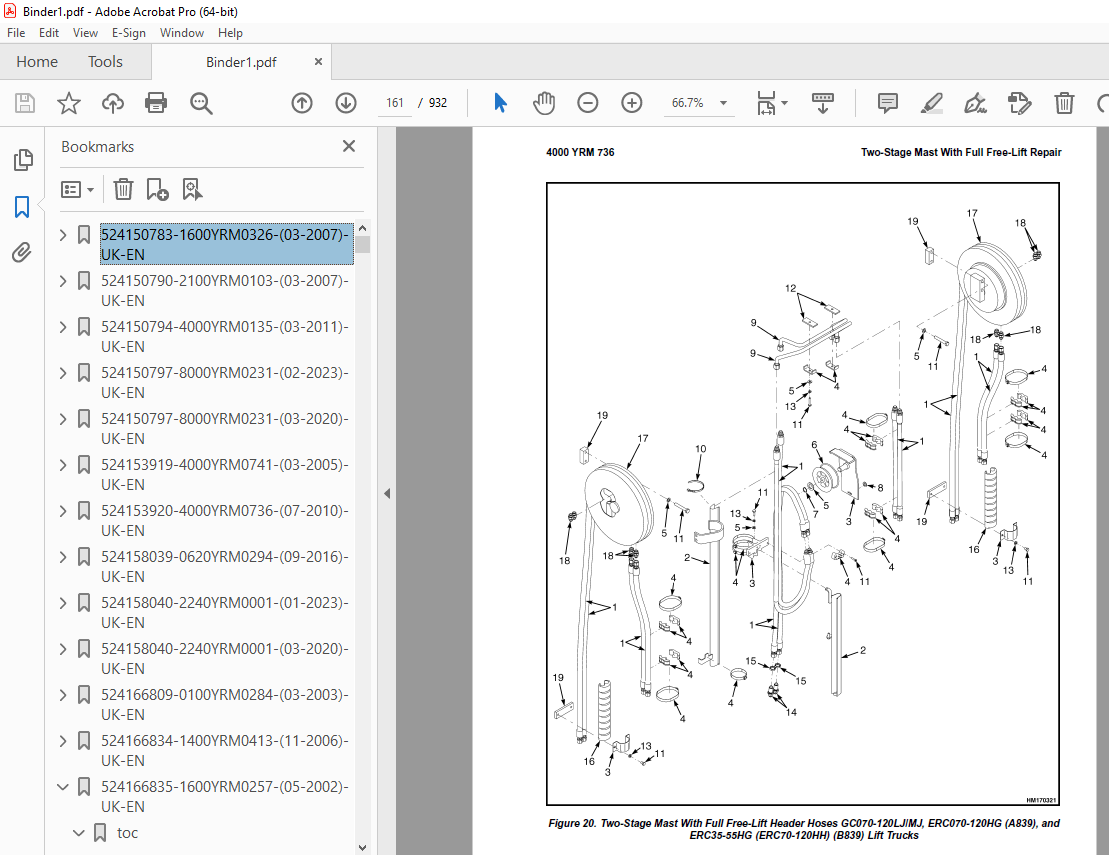
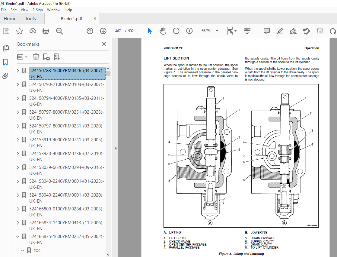
TABLE OF CONTENTS:
Yale Forklift A839 (ERC35-40-45-55HG) Service Manual – PDF DOWNLOAD
524150783-1600YRM0326-(03-2007)-UK-EN 1
toc 1
Steering Axle 1
Safety Precautions Maintenance and Repair 2
General 5
Description 5
Steering Axle Assembly Repair 10
Steering Axle GP/GLP/GDP070-110LG/MG (B813), GC/GLC070-120LG/MG 10
Remove 10
Install 10
Steering Axle GDP60-70CA (GP/GLP/GDP135-155CA) (A878, B878), GLP 11
Remove 11
Install 11
Wheels and Hubs Repair (All Units) 12
Remove and Disassemble 12
Clean 12
Inspect 12
Assemble and Install 12
Spindles and Bearings Repair (All Units) 14
Remove 14
Clean 14
Assemble and Install 15
Tie Rods Repair (All Units) 16
Remove 16
Clean 16
Install 16
Steering Cylinder Repair 19
Remove and Disassemble 19
Clean and Inspect 19
Assemble and Install 19
Troubleshooting 20
524150790-2100YRM0103-(03-2007)-UK-EN 25
toc 25
Tilt Cylinders 25
Safety Precautions Maintenance and Repair 26
General 29
Description 29
Tilt Cylinder Repair 29
Remove 29
Disassemble 29
Clean 29
Assemble 30
Tilt Cylinders With O-Ring or Single-Lip Seals 30
Tilt Cylinders 31
Install 32
Tilt Cylinder Leak Check 34
Tilt Cylinder Stroke and Mast Tilt Angle Adjustment 35
Torque Specifications 35
Piston Rod Nut 35
Retainer 35
Troubleshooting 36
tables 25
Table 1 Movement Rates (Maximum) for Tilt Cylinders 34
524150794-4000YRM0135-(03-2011)-UK-EN 41
toc 41
Lift Cylinders 41
Safety Precautions Maintenance and Repair 42
Safety Procedures When Working Near Mast 45
General 49
Description 49
Lowering Control Valve 49
Cylinders (General) 52
Lift Cylinder Repair 52
Lift Cylinder Removal Without Removing Mast 52
Standard Masts With Main Lift Cylinder Fastened to Crossmember o 52
Standard and Full Free-Lift Masts With Lift Cylinder Fastened to 53
Masts That Have Two Cylinders, Main Lift Cylinder and Free-Lift 54
Disassemble 54
Assemble 54
Lift Cylinder Installation in Mast 56
Standard Masts With Main Lift Cylinder Fastened to Crossmember o 56
Standard and Full Free-Lift Masts With Lift Cylinder Fastened to 56
Chevron-Style Packing 57
Chevron-Style Packing Installation on Piston 57
Chevron-Style Packing Installation in Packing Gland 59
Lift Cylinders for HI VIS® Masts 61
Description 61
Lowering Control Valve 61
Remove 63
Disassemble 64
Assemble 64
Install 66
Main Lift Cylinders 66
Free-Lift Cylinder 66
Lift System Leak Check 66
Specifications 67
Troubleshooting 68
tables 41
Table 1 Cylinder Retainer Torque Specifications and Weight Guid 67
524150797-8000YRM0231-(02-2023)-UK-EN 73
General 79
Threaded Fasteners 79
Nomenclature, Threads 79
Strength Identification 80
Cotter (Split) Pins 81
Fastener Torque Tables 86
Conversion Table 88
524153919-4000YRM0741-(03-2005)-UK-EN 95
toc 95
Lift Cylinders 95
Safety Precautions Maintenance and Repair 96
Safety Procedures When Working Near Mast 99
General 101
Description 101
Lowering Control Valve (Velocity Fuse) 101
Lift Cylinder Repair 104
Remove 104
Disassemble 105
Assemble 105
Install 105
Lift System Leak Check 106
Troubleshooting 107
524153920-4000YRM0736-(07-2010)-UK-EN 111
toc 111
Masts 111
Safety Precautions Maintenance and Repair 112
General 115
Description and Operation 115
Carriages 115
Two-Stage Mast With Limited Free-Lift 115
Two-Stage Mast With Full Free-Lift 116
Three-Stage Mast With Full Free-Lift 117
Safety Procedures When Working Near Mast 119
Fork Replacement 121
Remove 122
Install 122
Carriage Repair 123
Remove 123
Sideshift Carriage Repair 125
Remove 125
Disassemble 125
Assemble 125
Install 125
Two-Stage Mast With Limited Free-Lift Repair 127
Remove, GLP/GDP3 5-5 5LJ/MJ (GP/GLP/GDP070-120LJ/MJ) Model Lift 127
Remove, GC070-120LJ/MJ, ERC070-120HG (A839), and ERC35-55HG (ERC 129
Disassemble 132
Clean and Inspect 132
Assemble 133
Install, GLP/GDP3 5-5 5LJ/MJ (GP/GLP/GDP070-120LJ/MJ) Lift Truck 134
Install, GC070-120LJ/MJ, ERC070-120HG (A839), and ERC35-55HG (ER 136
Two-Stage Mast With Full Free-Lift Repair 138
Remove 138
Disassemble 138
Clean and Inspect 140
Assemble 140
Install 140
Three-Stage Mast With Full Free-Lift Repair 142
Remove 142
Disassemble 142
Clean and Inspect 146
Assemble 146
Install 147
Mast Operation Check 153
Lift and Tilt System Leak Check 154
Lift System 154
Tilt System 155
Tilt Cylinder Stroke and Backward Tilt Angle Adjustment 156
Lift Chain Adjustments 158
Mast Adjustments 160
Carriage Adjustment 162
Troubleshooting 163
tables 111
Table 1 Tilt Cylinder Leak Check Specifications, GC070-120LJ/MJ 155
Table 2 Hook-Type Carriage Chain Adjustment 158
Table 3 Pin-Type Carriage Chain Adjustment 159
524158039-0620YRM0294-(09-2016)-UK-EN 169
General 173
Brush and Commutator Inspection 174
Hydraulic Pump Motor and Traction Motor 174
Steering Pump Motor 177
Normal Commutator Surface 177
Commutator Problems 177
Brush Replacement 182
Stoning the Commutator 185
Motors Repair 186
Disassemble 187
Traction Motor and Hydraulic Pump Motor 187
Steering Pump Motor 188
Assemble 192
Traction Motor and Hydraulic Pump Motor 192
Steering Pump Motor 194
Brush Alignment, Traction and Hydraulic Motors 196
Tests for Damaged Field and Armature 197
Test for an Open Circuit in One Armature Winding 197
Test for Short Circuit in One Armature Winding 197
Test for Short Circuit to Armature Shaft 198
Test for Open Circuit in Field Coil 198
Test for Short Circuit in Field Coil 199
Test for Short Circuit Between Field and Motor Case 199
Brush Holder Test 199
Troubleshooting 200
524158040-2240YRM0001-(01-2023)-UK-EN 205
General 211
Battery Type 211
Lead-Acid Batteries 211
Lithium-Ion Batteries 212
Specific Gravity 212
Chemical Reaction in a Cell 212
Electrical Terms 214
Battery Selection 215
Battery Voltage 216
Battery as a Counterweight 216
Battery Ratings 216
Kilowatt-Hours 216
Battery Maintenance 217
Safety Procedures 217
Maintenance Records 217
New Battery 217
Cleaning Battery 218
Adding Water to Battery 220
Hydrometer 220
Battery Temperature 221
Charging Battery 222
Types of Battery Charges 223
Methods of Charging 224
Troubleshooting Charger 225
Knowing When Battery Is Fully Charged 225
Where to Charge Batteries 225
Equipment Needed 225
Battery Connectors 226
Battery Care 226
Troubleshooting 228
524166809-0100YRM0284-(03-2003)-UK-EN 233
toc 233
Frame 233
Safety Precautions Maintenance and Repair 234
General 237
Description 237
Overhead Guard Repair 240
Remove 240
Install 240
Battery Restraint and Seat Assembly Repair 241
Seat Brake Assembly, Adjust 242
Counterweight Repair 244
Remove 244
Install 244
Traction Motor Repair 245
Remove 245
Install 246
Hydraulic Tank Repair 246
Inspect 246
Small Leaks, Repair 246
Large Leaks, Repair 247
Clean 247
Steam Method 247
Chemical Solution Method 248
Additional Preparations For Repair 248
Painting Instructions 248
Safety Label Replacement 249
tables 233
Table 1 Battery Specifications 238
Table 2 Seat Brake Adjustment 243
Table 3 Counterweights 244
524166834-1400YRM0413-(11-2006)-UK-EN 255
toc 255
Drive Axle, Speed Reducer, and Differential 255
Safety Precautions Maintenance and Repair 256
General 259
Description 259
Drive Axle, Speed Reducer, and Differential Repair 260
Remove 260
General 260
Traction Motor, Speed Reducer, and Differential 261
Motor, Speed Reducer, and Differential, Remove 261
Disassemble 264
Speed Reducer 264
Differential 265
Clean 266
Inspect 266
Assemble 266
Speed Reducer 266
Input Gear, Install 266
New Pinion, Install 266
Differential 269
Drive Axle Housing 272
Remove 272
Clean 273
Inspect 273
Assemble 273
Troubleshooting 276
tables 255
Table 1 Pinion Assembly Shims Adjustment 268
Table 2 Ring and Pinion Tooth Contact Adjustment 270
524166835-1600YRM0257-(05-2002)-UK-EN 279
toc 279
Steering Control Unit 279
Safety Precautions Maintenance and Repair 280
General 283
Description 283
Control Valve Section 283
Metering Section 283
Disassembly and Inspection 284
Disassemble and Inspect 288
Assembly 304
Assemble 304
Troubleshooting 327
524166836-1600YRM0485-(07-2003)-UK-EN 331
toc 331
Steering System for Electric Lift Trucks 331
Safety Precautions Maintenance and Repair 332
General 335
Description 337
Steering Wheel and Column Assembly Repair 338
Assembly Components, Remove 338
Assembly Components, Install 342
Power Steering Motor and Pump 343
Description 343
Remove and Disassemble, Models ERC 20-30AGF (ERC040-065RF/ZF, RG 344
Remove and Disassemble, Models ERC35-55HG (ERC70-120HD, ERC70-12 345
Remove and Disassemble, Models ERP20-30ALF 348
Remove and Disassemble, Models ERC/P16-20AAF (ERC040-065AF, AG/B 348
Assemble and Install, All Models With A Vertical Mount Except ER 349
Assemble and Install, Models ERP20-30ALF 349
Assemble and Install, Models ERC/P16-20AAF (ERC030-040AF, AG/BG) 350
Power Steering Pump, Repair 350
Seal, Replace 351
Hydraulic Steering Motor 352
Steering System Air Removal 352
Steering Pressure Check 352
Optical Encoder and Activator Circuits Check 353
Troubleshooting 355
524166837-1800YRM0338-(05-2009)-UK-EN 359
toc 359
Brake System 359
Safety Precautions Maintenance and Repair 360
General 363
Description and Operation 363
Brake Booster and Master Cylinder 363
Master Cylinder 363
Service Brake Assembly 363
Parking Brake 367
Seat Brake 368
Brake Shoe Assemblies Repair 369
Remove and Disassemble 369
Clean and Inspect 369
Assemble and Install 371
Master Cylinder Repair 375
Master Cylinder For Lift Truck Models GC/GLC70-120LG/MG (B818) a 375
Remove 375
Disassemble 375
Assemble 376
Install 376
Master Cylinder For Lift Truck Models ERC70-120HD, ERC70-120HG ( 377
Remove and Disassemble 377
Clean and Inspect 378
Assemble and Install 378
Brake Booster Repair 378
Remove 378
Disassemble 378
Clean and Inspect 379
Assemble 380
Install 380
Brake System Air Removal 380
Brake Pedal Adjustment 380
Brake Pedal GP/GLP/GDP70-120LG/MG (B813) With Manual Transmissio 380
Brake Shoes Adjustment 382
Parking Brake Adjustment 382
Parking Brake Adjustment, Lift Truck Models GC/GLC70-120LG/MG (B 382
Parking Brake Lever and Switch Adjustment ERC70-120HD and ERC70- 383
Seat Brake Assembly 384
Remove 384
Clean and Inspect 384
Install 384
Adjustments 386
Solenoid Adjustment 386
Traction cutoff Switch Adjustment 386
Cable Adjustment 386
Brake Booster Relief Valve Check 389
Troubleshooting 389
524166838-1900YRM0286-(07-2002)-UK-EN 395
toc 395
Hydraulic System 395
Safety Precautions Maintenance and Repair 396
General 399
Description 399
Hydraulic System 399
Operation 400
Hydraulic System 400
Hydraulic Pump 401
Steering Pump 402
Hydraulic Pump Repair 402
Remove 402
Seal, Replace 403
Install 404
Main Control Valve Check and Adjust 404
Linkage and Switches 405
Relief Valve 405
Steering Relief Valve Check and Adjust 407
Specifications 407
Relief Valve Pressures 407
Capacities 407
Hydraulic Pump Capacities 407
Troubleshooting 408
524166839-2000YRM0077-(02-2009)-UK-EN 413
toc 413
Manual hydraulic Control Valve 413
Safety Precautions Maintenance and Repair 414
General 417
Description 417
Operation 419
Lift Section 421
Tilt Section 422
Tilt Backward 422
Tilt Forward 422
Relief Valve 424
Solenoid Valve for Auxiliary Function 425
Main Control Valve Repair 426
Remove and Disassemble – Control Valve Without OPS Solenoid 426
Remove and Disassemble – Control Valve With OPS Solenoid 426
Clean and Inspect 428
Assemble – Control Valve Without OPS 428
Assemble – Control Valve With OPS 428
Install 429
Solenoid Valve for Auxiliary Function Repair 429
Remove and Disassemble 429
Assemble and Install 431
Troubleshooting 431
Pressure Relief Valve Check and Adjustment 432
Primary Relief Valve 432
Secondary Relief Valve 432
Control Lever Arrangement and Adjustment 433
Specifications 435
Troubleshooting 435
524166840-2200YRM0560-(07-2005)-UK-EN 441
toc 441
Electrical System 441
Safety Precautions Maintenance and Repair 442
General 447
Description 448
ZX Series Display Panels 448
Optional Basic Display Panel 448
Features of the Optional Basic Display Panel 448
Description of Features on the Optional Basic Display Panel 448
Standard Display Panel 449
Features of the Standard Display Panel 449
Description of Features on the Standard Display Panel 449
Premium Display Panel 450
Features on the Premium Display Panel 450
Description of Features on the Premium Display Panel 451
Curtis 1215 Display Panel 453
Description and Features 453
Operation 453
SEM Display Panels – Features 454
Descriptions of Common Features 455
LED Symbol Indicators – SEM 455
LCD Screen 455
Battery Discharge Indicator (BDI) 455
Service Reminder 456
Status Codes 456
Hourmeter 456
Additional Features of Premium Display Panel 457
Descriptions of Additional Features 457
LCD Screen 457
Operator Passwords 457
Daily Checklist and Service Items 457
Performance Modes 457
Status Code Lists 458
Adjustment of BDI 458
SEM Display Panel Indicators 458
All Indicator Symbols 458
Hourmeter Indicator Symbol 458
Wrench Symbol 458
Battery Symbol 458
Battery Discharge Indicator (BDI) 458
Brake Fluid Too Low Symbol 458
Parking Brake Symbol 458
Fasten Seat Belt Symbol 459
LCD Screen (Standard Display Panel) 459
Additional Components of Premium Display Panel 459
Alpha Numerical Screen 459
STAR Push Button 459
Push Buttons ##1 Through ##5 – SEM 459
Other Control Components 459
Display Panel Components – ZX, and Curtis Replacement 460
ZX Panel Replacement 460
Curtis 1215 Display Panel Replacement 465
Remove 465
Install 465
SEM Display Panel Replacement 466
Motor Controller (SR or SP) Replacement 466
Remove 466
Install 466
Control Components Replacement 468
Start Switch, Replace 468
Brake Light Switch, Replace 469
Seat Switch, Replace 469
External Seat Switch, Adjust 470
Switch for Optional Seat Brake, Replace 471
Parking Brake Switch, Replace 471
Direction Switches Foot Directional Control Replace 472
Direction Control Switches (Steering Column), Replace 473
Direction Control Switches, ERC070-120HG (Steering Column), Repl 474
Brake Fluid Switch, Replace 474
Brush Wear and Overtemperature Sensors 474
Rocker Switches for Lights 475
Accelerator Position Sensor, Replace 475
On-Demand Steering Components 477
Lights, Converter, Relay, and Reverse Alarm 479
Incandescent Brake, Tail, and Reverse Light Assembly, Replace 479
LED Brake, Tail, and Reverse Light Assembly, Replace 481
Remove 481
Install 481
Flashing Light Assembly, Replace 481
Front, Rear Driving Light, or Spot Light Assemblies, Replace 483
Operator Compartment Light Assembly, Replace 483
Converter, Replace 484
Relay, Replace 484
Reverse Alarm, Replace 484
Horn and Horn Button 484
Horn Switch and Cover 485
Hydraulic Pump Switches 485
Control and Power Fuses Check 486
ZX Motor Controllers 486
SEM Motor Controllers 486
SEM Controller Field Diagnostic Procedure 491
Armature FET Test 491
Field FET Test 491
Brush Wear and Overtemperature Sensors Check – ZX Motor Controll 495
Thermal Sensors – SEM Motor Controllers Check 496
Start Switch Adjustment 497
Accelerator Potentiometer and Start Switch, ERC070-120HG Lift Tr 498
ERC070-120HG 498
Direction Switches Foot Directional Control Pedal 499
Brake Light Switch Adjustment 500
Seat Switch Check 501
Optional Seat Brake Switch Adjustment 501
Parking Brake Switch Adjustment 502
Direction Switches Check 502
Foot Directional Control Pedal 502
Steering Column 503
Hydraulic Pump Switch Adjustment 503
Foot Directional Control or Accelerator Pedal Adjustment 503
Accelerator Position Sensor Adjustment 504
524166842-2200YRM0725-(07-2002)-UK-EN 509
toc 509
SEM Display Panel 509
Safety Precautions Maintenance and Repair 510
General 513
SEM Display Panel Features 513
Common Features Descriptions 513
LED Symbol Indicators 513
LCD Screen 513
Battery Discharge Indicator (BDI) 513
Service Reminder 514
Status Codes 514
Hourmeter 514
Premium Display Panel Additional Features 515
Additional Features Descriptions (Available With Premium Display 515
LCD Screen 515
Operator Passwords 516
Daily Check List and Service Items 516
Performance Modes 516
Status Code Lists 516
BDI, Adjust 516
SEM Display Panel Indicators 517
All Indicator Symbols 517
Hourmeter Indicator Symbol 517
Wrench Indicator Symbol 517
Battery Indicator Symbol 517
Battery State-of-Charge (BDI) 517
Brake Fluid Low Symbol 517
Parking Brake Symbol 517
Fasten Seat Belt Symbol 517
LCD Screen (Standard Display Panel) 517
Premium Display Panel Additional Components 518
Alpha Numerical Screen 518
STAR Push Button 518
Push Buttons ##1 Through ##5 518
Computer Adjustments 518
Computer System 518
Connect PC to SEM Display Panel 519
ITW Switches Software Program (for SEM Display Panel) 519
Description 519
Where to Get Help 520
Hardware and Software Requirements 520
How to Start ITW Switches Program 520
Menus 521
Create a Setup File 526
SEM Display Panel Replacement 543
General 543
Remove and Replace 543
tables 509
Table 1 Adapter Pins (DB25F to DB9) 518
524166843-2200YRM0808-(06-2005)-UK-EN 549
toc 549
Transistor Motor Controllers (SR and SP) 549
Safety Precautions Maintenance and Repair 550
Description 553
Model Number Data for Transistor Motor Controllers (SR and SP) 554
Motor Controller Checks and Adjustments 557
Checks and Adjustments Using a Handset 557
General 557
Connect Handset 558
Start Sequence 558
Check or Delete Stored Status Codes 559
Returning Lift Truck to Normal Operation 560
Checks and Adjustments on Workbench 560
How to Check and Adjust Registers 560
Function Parameters Adjustments 562
General 562
Function Numbers 563
When Handset is Connected to Motor Controller in Lift Truck 563
Function Numbers 1 through 15 563
Function Numbers 16 through 30 563
Function Numbers 48 through 63 564
Function Number Descriptions 564
Traction Motor Controller (Label Letter – SR) 564
Functions with Premium Display Panel Only 569
Pump Motor Controller (Label Letter – SP) 571
Functions With Premium Display Panel Only 573
Troubleshooting 579
General 579
Status Codes 579
Status Code Charts 582
Transistor Motor Controllers Repairs 614
General 614
General Maintenance Instructions 617
Special Precautions 617
Fuses 617
Contactors 618
Repair 618
Contactor Driver Module 618
Contactor Driver, Replace 618
Motor Controller Plug 621
Brush Wear Indicators 622
Thermal Sensors 623
Motor Controller, Replace 623
Parameter Tables 626
General 626
Function Numbers 626
Motor Controller Checks and Adjustments 626
Parameter Tables 627
Theory of Operation 634
General 634
SEM System Description 635
SEM System Operation (SR Motor Controller) 635
Reverse Circuit 635
Performance and Efficiency 636
Field Weakening 636
Regenerative Braking 636
Creep Speed 637
Controlled Acceleration 637
Current Limit 637
Braking 637
Regenerative Braking to Zero Speed 637
Pedal Position Braking 637
Auto Braking 637
Auxiliary Speed Control 638
Field Weakening 638
Speed Limits 638
Ramp Operation 638
Ramp Start 638
Anti-Rollback 638
Steer Pump Contactor Time Delay 638
Coil Drivers and Internal Coil Suppression 638
System Protective Override 638
SRO (Static Return to Off) 638
Accelerator Volts Hold Off 638
Pulse Monitor Trip (PMT) 638
Thermal Protector (TP) 639
Low Voltage 639
SP Pump Motor Controllers 639
Contactor Driver Module 639
Diagnostics 639
Systems Diagnostics 639
Standard Status Codes 640
Stored Status Codes 640
Hourmeter Readings 640
Maintenance Management Capability 640
tables 549
Table 1 Speed/Torque Compensation 573
Table 2 Function Map for Motor Controllers SR (Traction) 575
Table 3 Function Map for Motor Controllers SP (Lift Pump Motor) 577
Table 4 List of Status Codes 580
Table 5 Large (P) Plug (23-Pin) Connections/Descriptions for Mo 621
Table 6 Small Plug (12-Pin) Connections/Descriptions for Motor 622
Table 7 Traction Control – SR Transistor Control Settings, 11-I 627
Table 8 Traction Control – SR Transistor Control Settings, 13-I 629
Table 9 Traction Control – SR Transistor Control Settings, 13-I 631
Table 10 Hydraulic Pump – SR Transistor Control Settings (36/48 632
524166844-2200YRM0942-(08-2007)-UK-EN 643
toc 643
Display Panel for SEM Controls 643
Safety Precautions Maintenance and Repair 644
General 647
SEM Display Panel Features 647
Descriptions of Common Features 647
LED Symbol Indicators 647
LCD Screen 647
Battery Discharge Indicator (BDI) 648
Service Reminder 648
Status Codes 648
Hourmeter 648
Additional Features of Premium Display Panel 648
Descriptions of Additional Features (Available With Premium Disp 648
LCD Screen 648
Operator Passwords 649
Daily Check List and Service Items 649
Performance Modes 649
Status Code Lists 649
Adjustment of BDI 649
SEM Display Panel Indicators 650
All Indicator Symbols 650
Hourmeter Indicator Symbol 650
Wrench Indicator Symbol 650
Battery Indicator Symbol 650
Battery State-of-Charge (BDI) 650
Brake Fluid Too Low Symbol 651
Parking Brake Symbol 651
Fasten Seat Belt Symbol 651
LCD Screen (Standard Display Panel) 652
Additional Components of Premium Display Panel 652
Alphanumeric Screen 652
STAR Push Button 652
Push Buttons 1 Through 5 652
Adjustments With a Computer 652
Computer System 652
Connect PC to SEM Display Panel 653
ITW Switches Windows Software Program (for SEM Display Panel) 654
Description 654
Getting Help 654
Hardware and Software Requirements 654
Install 654
How to Start ITW Switches Program 654
Menus 658
Sample Sessions 667
Replacement 689
SEM Display Panel 689
Remove and Replace 689
tables 643
Table 1 Adapter Pins (DB25F to DB9) 653
524166845-4000YRM0340-(09-2002)-UK-EN 695
toc 695
Masts 695
Safety Precautions Maintenance and Repair 696
General 699
Description and Operation 699
Carriages 699
Two-Stage Mast With Limited Free-Lift 699
Two-Stage Mast With Full Free-Lift Mast 700
Three-Stage Mast With Full Free-Lift 701
Safety Procedures When Working Near Mast 703
Forks Replacement 705
Remove and Install 705
Hook Fork 705
Remove 705
Install 705
Pin Fork 706
Remove 706
Install 706
Carriage Repair 706
Remove 706
Sideshift Carriage Repair 708
Sideshift Carriage (Earlier Designs) 708
Disassemble 708
Assemble 709
Install 712
Sideshift Carriage (1993 and Later Design) 712
Remove 712
Repairs 712
Install 712
Weight of Mast Parts 715
Two-Stage Mast With Limited Free-Lift Repair 715
Remove 715
Disassemble 717
Clean and Inspect 717
Assemble 717
Install 719
Two-Stage Mast With Full Free-Lift Repair 719
Remove 719
Disassemble 719
Clean and Inspect 721
Assemble 721
Install 721
Three-Stage Mast With Full Free-Lift 722
Remove 722
Disassemble 722
Clean and Inspect 722
Assemble 722
Install 724
Mast Operation Check 726
Lift and Tilt System Leak Check 727
Lift System 727
Tilt System 727
Tilt Cylinder Stroke and Backward Tilt Angle Adjustment 728
Lift Chain Adjustments 728
Mast Adjustments 729
Carriage Adjustment 731
Troubleshooting 732
524166846-8000YRM0915-(07-2002)-UK-EN 737
toc 737
Periodic Maintenance 737
Safety Precautions Maintenance and Repair 738
General 741
Serial Number Data 741
How to Move Disabled Lift Truck 741
How to Tow Lift Truck 741
How to Put Lift Truck on Blocks 742
How to Raise Drive Tires 742
How to Raise Steering Tires 743
Maintenance Schedule 743
Maintenance Procedures Every 8 Hours or Daily 746
How to Make Checks with Key Switch OFF 746
Tires and Wheels 746
Forks 746
Adjust 746
Remove 746
Install 748
Inspect Mast, Forks, and Lift Chains 748
Safety Labels 749
Steering Column Latch 749
Operator Restraint System 749
Battery Restraint System 750
Battery 751
Hydraulic System 751
How to Make Checks with Key Switch ON 752
Gauges, Horn, and Fuses 752
Steering System 752
Service Brakes 752
Parking Brake 752
Control Levers and Pedals 752
Lift System Operation 753
Maintenance Procedures Every 500 Hours or 3 Months 753
Differential and Speed Reducer 753
Wheel Nuts 753
Steering Axle Spindles 753
Mast 754
Brake Fluid 754
Other Lubrication 755
Seat Brake 755
Electrical Inspection 755
Contactors 755
Motor Brushes 755
Maintenance Procedures Every 1000 Hours or 6 Months 757
Lift Chains 757
Wear Check 757
Lubrication 757
Forks 757
Maintenance Procedures Every 2000 Hours or Yearly 758
Hydraulic System 758
Hydraulic Tank Breather 758
Change Filter for Hydraulic Oil 758
Change Hydraulic Oil 758
Differential and Speed Reducer 758
Service Brakes 759
Contactors 759
Wheel Bearings 759
Steer Wheels, Lubrication 759
Drive Wheels, Lubrication 759
Lift Chains 759
Battery Maintenance 760
How to Charge Battery 760
How to Change Battery 761
Safety Procedures When Working Near Mast 764
Lift and Tilt System Leaks Check 766
Check Lift Cylinders for Leaks 766
Check Tilt Cylinders for Leaks 766
Lift Chain Adjustments 767
How to Check PMT Circuit 769
Welding Repairs 770
Overhead Guard Changes 770
Tires and Wheels 770
General 770
Remove Wheels from Lift Truck 771
Remove Tire from Wheel and Install Tire on Wheel 771
Install Wheels 771
Battery Specifications 772
tables 737
Table 1 Maintenance Schedule 744
Table 2 Hook-Type Carriage Chain Adjustment 767
Table 3 Pin-Type Carriage Chain Adjustment 768
524166847-8000YRM0916-(07-2002)-UK-EN 775
toc 775
Capacities and Specifications 775
Safety Precautions Maintenance and Repair 776
Lift Truck Weights 779
Tire Sizes 779
Capacities 779
Hydraulic System 779
Mast Speeds 780
Mast Creep Speeds 781
Battery Specifications 781
Traction Speed and Traction Motor Current 782
Hoist Motor Current 783
Torque Specifications 783
Brake System 783
Differential 783
Drive Axle 783
Frame 783
Mast 783
Main Control Valve 783
Steering System 784
Tilt Cylinders 784
524166848-8000YRM0917-(01-2004)-UK-EN 787
toc 787
Diagrams 787
Safety Precautions Maintenance and Repair 788
524167640-2200YRM0947-(08-2007)-UK-EN 813
toc 813
Troubleshooting and Adjustments With a Computer 813
Safety Precautions Maintenance and Repair 814
Computer System 817
Connect a PC to a Control Card 818
Installation 819
SMARTSET™ Windows Software Program 819
How to Start the Program 819
DEMO Mode 820
Selecting the Communications Port 822
Verification of Controller and Lift Truck 823
Select Lift Truck Series 825
Controller Card Register Parameter List 826
How to Change a Parameter 827
How to Save a Changed Parameter File 828
How to Load a Saved Parameter File 830
How to Show and Remove Saved Parameter Files 830
How to Return to Factory Default Settings 831
How to Save Changes to Control Card 832
How to View Status Codes 833
Saving Status Codes 834
How to Show and Remove Saved Status Code Files 835
Closing and Clearing Status Code List 836
How to View Saved Register Data and Saved Status Data 837
How to Save Register Data and Status Code Data In RTF and TXT 839
GE Sentry™ Software Program 840
Installation 840
Description 840
How to Start GE SENTRY Program 840
How to Reset MIN and MAX Display 845
Graphing Mode 846
How to Exit GE SENTRY Program 847
tables 813
Table 1 Cable Connections – Computer to Control 817
Table 2 Adapter Pins (DB25F to DB9) 818
Table 3 Plug-Z Connection 819
524179949-2200YRM0595-(07-2003)-UK-EN 851
toc 851
EV-100ZX™ SCR Motor Controller 851
Safety Precautions Maintenance and Repair 852
Register Parameters 855
General 855
Function Numbers 855
Control Card Checks and Adjustments 856
Register Parameter Tables 856
tables 851
Table 1 EV-100ZX Parameters – ERC040-065RF/ZF, and ERP20-30ALF 857
Table 2 EV-100ZX Parameters – ERC040-065RF/ZF (36 to 48V) (Trac 861
Table 3 EV-100ZX Parameters – ERC20-30AGF, and ERP20-30ALF (72 865
Table 4 EV-100ZX Parameters – ERC20-30AGF (72 to 80V) (Traction 869
Table 5 EV-100ZX Parameters – ERC20-30AGF (72 to 80V) (Low Ener 873
Table 6 EV-100ZX Parameters – ERC70-120HD, ERC040-065RF/ZF, and 877
Table 7 EV-100ZX Parameters – ERC35-55HG, ERC20-30AGF, and ERP2 881
Attachments and Hose Take-Up 887
Brake System 905
Drive Unit Assembly 921
Electrical System 949
Field Conversion Kits 1001
General Information 1005
General Truck 1017
Hydraulic System 1071
Lifting Mechanism 1125
New Text Document 1183
Numerical Index 1184
Options 1206
Steering System 1220
User Support Information 1246
More products