$40.95
Yale Forklift A875 (GDPGLP20-30RFTF Europe) Service Manual – PDF DOWNLOAD
Yale Forklift A875 (GDPGLP20-30RFTF Europe) Service Manual – PDF DOWNLOAD
FILE DETAILS:
Yale Forklift A875 (GDPGLP20-30RFTF Europe) Service Manual – PDF DOWNLOAD
Language : English
Pages : 1576
Downloadable : Yes
File Type : PDF
IMAGES PREVIEW OF THE MANUAL:
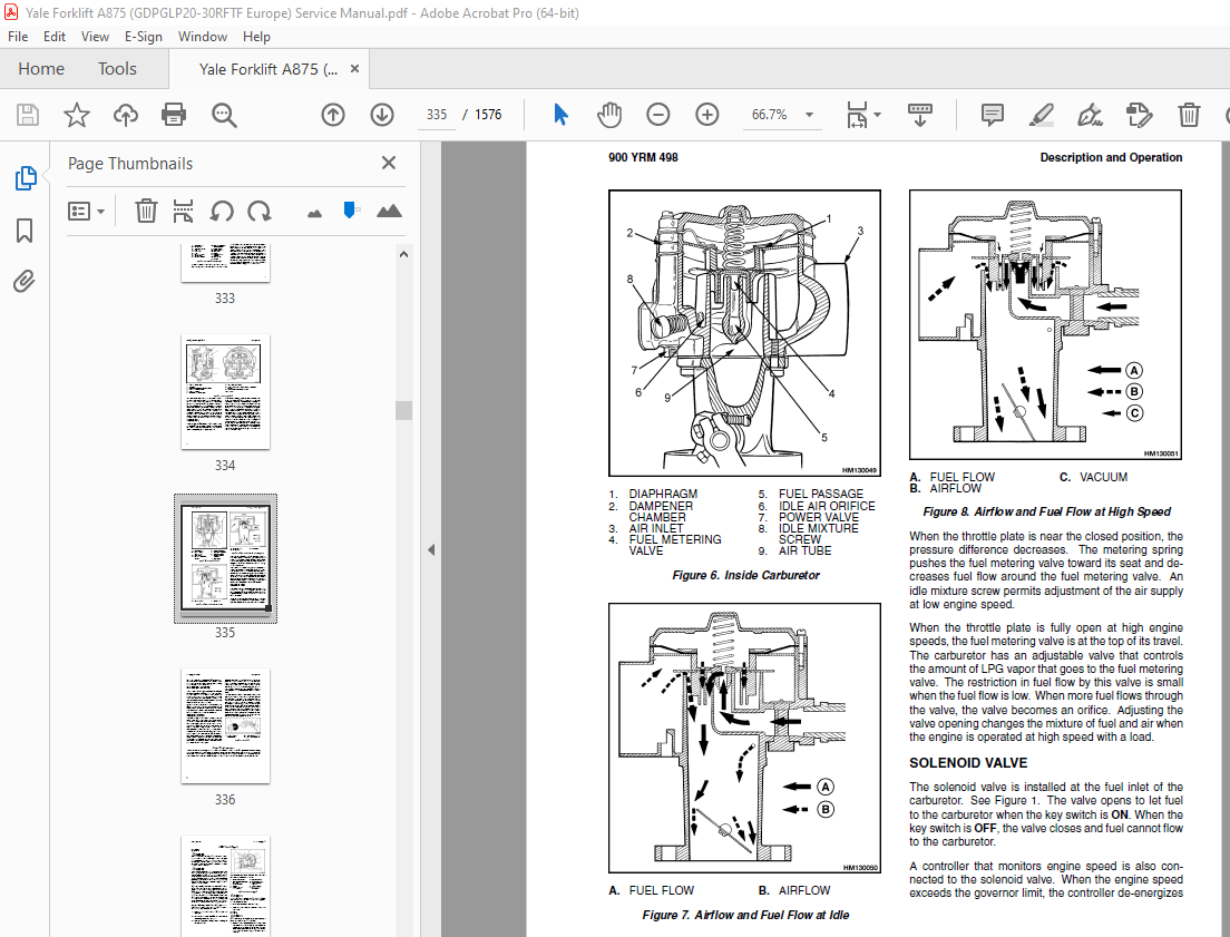
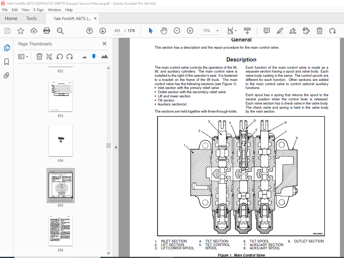
TABLE OF CONTENTS:
Yale Forklift A875 (GDPGLP20-30RFTF Europe) Service Manual – PDF DOWNLOAD
524150775 0700YRM0626 (03 2003) UK EN 1
toc 1
Cooling System 1
Safety Precautions Maintenance and Repair 2
General 5
Description 6
Radiator 6
Radiator Cap 6
Thermostat 6
Water Pump 7
Fan and Fan Shroud 7
Cooling System Checks 7
Radiator 7
Thermostat 7
Water Pump 8
Exhaust Leaks 8
Fan and Fan Shroud 8
Radiator Cleaning 8
Drain 8
Clean 8
Fill 9
Troubleshooting 10
524150790 2100YRM0103 (03 2007) UK EN 13
toc 13
Tilt Cylinders 13
Safety Precautions Maintenance and Repair 14
General 17
Description 17
Tilt Cylinder Repair 17
Remove 17
Disassemble 17
Clean 17
Assemble 18
Tilt Cylinders With O-Ring or Single-Lip Seals 18
Tilt Cylinders 19
Install 20
Tilt Cylinder Leak Check 22
Tilt Cylinder Stroke and Mast Tilt Angle Adjustment 23
Torque Specifications 23
Piston Rod Nut 23
Retainer 23
Troubleshooting 24
tables 13
Table 1 Movement Rates (Maximum) for Tilt Cylinders 22
524150791 2200YRM0002 (01 2016) UK EN 29
General 33
Description 34
Alternator Repair 36
Alternator Type A 36
Remove and Disassemble 36
Clean 38
Assemble 38
Install 39
Alternator Type B 42
Remove and Disassemble 42
Clean 42
Assemble 43
Install 44
General Check and Adjustment 44
Low Output Check (Type A or Type B) 45
High Output Check (Type A or Type B) 48
Brushes Circuit Check 49
Delco Alternators 49
Motorola Alternators 49
Diodes Check 50
Diode Bridge Check 50
Delco and Leece-Neville Alternators 50
Motorola Alternators 50
Rotor Field Winding Check 51
Stator Windings Check 52
Voltage Regulator Check 52
Troubleshooting 52
524150792 2200YRM0106 (01 2016) UK EN 57
General 61
Description and Operation 62
Starter Repair 66
Remove 66
Disassemble 66
Clean 67
Assemble 67
Install 68
General Checks and Adjustments 68
Troubleshooting 70
524150797 8000YRM0231 (02 2023) US EN 77
General 83
Threaded Fasteners 83
Nomenclature, Threads 83
Strength Identification 84
Cotter (Split) Pins 85
Fastener Torque Tables 90
Conversion Table 92
524150797 8000YRM0231 (03 2020) UK EN 99
General 103
Threaded Fasteners 103
Nomenclature, Threads 103
Strength Identification 104
Cotter (Split) Pins 105
Fastener Torque Tables 110
Conversion Table 112
524153914 2200YRM0107 (03 2008) UK EN 119
toc 119
High Energy Ignition (HEI) System 119
Safety Precautions Maintenance and Repair 120
Description 123
Distributor Repair 125
Remove 125
Disassemble 125
Assemble 131
Install, If Crankshaft WAS NOT Rotated when Distributor was Remo 132
Install, If Crankshaft WAS Rotated when Distributor was Removed 132
Ignition Coil Replacement 134
Some Four- and Six-Cylinder Models 134
Remove 134
Install 134
V8, Some Four- and Six-Cylinder Models 135
Remove 135
Install 135
Electronic Module Replacement 136
Remove 136
Install 136
Sensing Coil Replacement 138
Remove 138
Install 138
Spark Plugs Replacement 138
Remove 138
Install 139
Visual Check 139
High Voltage Wires Check 139
Ignition Coil Check 140
Coil in Distributor Cap Design 140
Separate Coil Design 140
Sensing Coil, Check 141
Electronic Module Check 141
Ignition Timing Adjustment 142
GM V8-366 (6-liter) Ignition System Check 143
GM V6-LPG (4 3 liter) GM V6-LPG (4 3 liter) Ignition Timing and 143
Specifications 143
Troubleshooting 144
524153916 2200YRM0765 (03 2003) UK EN 149
toc 149
Microprocessor Spark Timing System (MSTS) 149
Safety Precautions Maintenance and Repair 150
General 153
Description 154
What MSTS Does 154
How MSTS Begins Operation 154
Operation 155
Distributor 155
Ignition Coil 156
Ignition Module 156
When Engine Is Being Started 156
When Engine Is Running 158
Manifold Absolute Pressure (MAP) Sensor 159
Engine Coolant Temperature (ECT) Sensor 159
MSTS Module Corrections 160
Troubleshooting 161
General 161
Tools and Test Equipment 163
MSTS 164
Troubleshooting Procedure 164
Where to Start 164
Visual/Physical Inspection 164
Knowledge/Tools Required 164
Damage From Static Discharge (Static Electricity) 165
Troubleshooting Information 165
Malfunction Indicator Lamp (MIL) 165
Connecting CodeMate Tester 165
Reading Diagnostic Trouble Codes (DTC) 166
Clearing Diagnostic Trouble Codes (DTC’s) 167
On-Board Diagnostic (OBD) System Check 167
Test Description 167
No Malfunction Indicator Lamp 169
Circuit Description 169
Test Description 169
No DTC-12, Malfunction Indicator Lamp ON 171
Circuit Description 171
Test Description 171
Starter Rotates Engine, Engine Does Not Run 172
Test Description 172
DTC-14 Engine Coolant Temperature (ECT) (Low Temperature Indicat 176
Circuit Description 176
Test Description 176
DTC-15 Engine Coolant Temperature Sensor (ECT) (High Temperature 178
Circuit Description 178
Test Description 178
DTC-34 Manifold Absolute Pressure (MAP) Sensor 180
Circuit Description 180
Test Description 180
DTC-41 Electronic Spark Timing (EST) Open Circuit 183
Circuit Description 183
Test Description 183
DTC-42 Electronic Spark Timing (EST) Grounded Circuit 185
Circuit Description 185
Test Description 185
DTC-51 MSTS Failure 187
Circuit Description 187
Distributor Repair 187
Remove 187
Disassemble 188
Inspect 188
Assemble 188
Install 189
Ignition Timing 189
Ignition Module Repair 190
Test For Fault 190
Replace 190
Sensing Coil Repair 191
Test For Fault 191
Replace 191
Ignition Coil Repair 192
Test For Fault 192
Remove 192
Install 192
MSTS Module Repair 193
Remove 193
Install 193
ECT Sensor Replacement 193
MAP Sensor Replacement 194
tables 149
Table 1 MSTS Module Connections 162
Table 2 Pressure Conversion Chart 163
Table 3 MSTS Diagnostic Codes 165
524158636 0100YRM0505 (06 2004) UK EN 197
toc 197
Frame 197
Safety Precautions Maintenance and Repair 198
General 201
Description 201
Operator Module Repair 201
Remove 201
Install 201
Hood and Side Covers Repair 203
Remove 203
Install and Adjust 203
Overhead Guard Repair 205
Remove and Install 205
LED Backup and Brake Lights, Replace 206
Remove 206
Install 206
Counterweight Repair 207
Remove 207
Install 208
Exhaust System Repair 209
Muffler, Replace 210
Radiator and Cooling System Repair 216
Remove 216
Install 216
Operator Restraint System Repair 218
Engine Repair 219
Remove Engine Only 219
Remove Engine and Transmission 219
Install Engine Only 220
Install Engine and Transmission 221
Fuel and Hydraulic Tanks Repair 221
Inspect 221
Small Leaks, Repair 221
Large Leaks, Repair 221
Clean 222
Steam Method of Cleaning 222
Chemical Solution Method of Cleaning 222
Additional Preparations for Repair 222
Safety Labels 223
tables 197
Table 1 Weight of Counterweights 208
524158637 0600YRM1020 (10 2006) UK EN 229
toc 229
GM Engine Repair 229
Safety Precautions Maintenance and Repair 230
General 233
Description 233
Engine Removal and Installation 241
Cylinder Head and Valve Mechanism Repair 241
Cylinder Head, Remove 241
Cylinder Head, Disassemble 243
Clean and Inspect 243
Valves and Valve Seats 246
Studs for Rocker Arms 246
Hydraulic Valve Lifters 247
Replace 247
Clean and Inspect 247
Cylinder Head, Assemble 247
Cylinder Head, Install 248
Valve Clearance, Adjust 249
Rocker Arm Cover, Install 249
Timing Gear Cover Repair 250
Remove 250
Install 250
Timing Wheel Repair 251
Timing Wheel, Removal 251
Timing Wheel, Install 251
Air Gap Adjustment 252
Camshaft Repair 254
Camshaft, Remove 254
Camshaft, Clean and Inspect 254
Camshaft Bearings, Remove 256
Camshaft Bearings, Clean and Inspect 256
Camshaft Bearings, Install 256
Camshaft, Install 257
Distributor Repair 257
Remove 257
Install 258
Lubrication System Repair 259
Oil Pan 259
Remove 259
Install 259
Oil Pump 259
Remove 259
Disassemble 260
Clean and Inspect 261
Assemble 261
Install 261
Piston and Piston Rod Assemblies Repair 261
Piston Rod Bearings, Replace 261
Piston and Piston Rod Assemblies, Remove 263
Piston and Piston Rod Assemblies, Disassemble 263
Pistons, Clean and Inspect 264
Cylinder Bores, Inspect and Repair 264
Piston Rings, Inspect 265
Piston and Piston Rod Assemblies, Assemble 266
Piston and Piston Rod Assemblies, Install 266
Crankshaft Repair 267
Main Bearings, Replace 267
Oil Seal for Rear Main Bearing, Replace 268
Crankshaft, Remove 268
Inspect and Repair 269
Main Bearing and Journal Clearance, Check 270
Crankshaft, Install 271
Flywheel and Flywheel Housing Repair 271
Flywheel, Remove 272
Ring Gear, Replace 273
Flywheel, Install 273
Cooling System Repair 273
Water Pump 273
Remove 273
Inspect 273
Install 274
Thermostat 274
Remove and Install 274
Alternator Repair 274
Starter Repair 274
Checks and Adjustments 276
Engine Compression Test 276
Test Procedure 276
Test Results 276
Engine Noise Diagnostic Test 276
Description 276
Test Procedure 276
Engine Specifications 278
Engine Data 278
Cylinder Bore 278
Piston 278
Piston Rings 278
Wrist Pin 279
Crankshaft 279
Piston Rod 280
Camshaft 280
Hydraulic Valve System 280
Cylinder Head Warpage 281
Lubrication System 281
Cooling System 281
Torque Specifications 282
Troubleshooting 283
524158742 0600YRM0496 (01 2011) UK EN 289
toc 289
Mazda Engine 289
Safety Precautions Maintenance and Repair 290
General 293
Description 293
Engine Removal and Installation 293
Cylinder Head, Camshaft, and Valve Mechanism Repair 294
Remove 294
Clean 295
Inspect and Repair 296
Cylinder Head 296
Rocker Shaft Assembly 296
Camshaft 296
Valve Guides 297
Valve Seats 298
Valves 298
Valve Springs 299
Install 299
Crankshaft and Main Bearings Repair 302
Remove 302
Inspect and Repair 302
Crankshaft 302
Main Bearings 302
Install 303
Pistons and Connecting Rods Repair 304
Remove and Disassemble 304
Clean 304
Inspect and Repair 304
Pistons 304
Piston Rings 305
Connecting Rods and Bearings 305
Assemble and Install 306
Cylinder Block Repair 307
Oil Pump Repair 307
Remove 307
Disassemble 308
Clean 308
Inspect 308
Assemble 309
Install 310
Cooling System Repair 310
Thermostat 310
Replace 310
Fan Assembly 310
Remove and Disassemble 310
Assemble and Install 311
Water Pump 311
Remove and Disassemble 311
Assemble and Install 312
Distributor Repair 313
Remove 313
Install 313
Flywheel and Ring Gear Repair 314
Remove 314
Ring Gear, Replace 314
Install 314
Flywheel Repair 315
Remove 315
Install 315
Valve Adjustment 316
Compression Pressure Check 316
Engine Timing Adjustment 317
Throttle Linkage Adjustment 317
Gasoline Engines 317
LPG Engines (IMPCO) 317
LPG Engines (AISAN) 318
Engine Specifications 318
Engine Data 318
Thermostat 318
Cylinder Head 318
Valve Mechanism 318
Camshaft 319
Crankshaft 319
Connecting Rods 320
Cylinder Block 320
Pistons 320
Oil Pump 320
Torque Specifications 321
Troubleshooting 322
524158744 0900YRM0498 (12 2003) UK EN 327
toc 327
LPG Fuel System 327
Safety Precautions Maintenance and Repair 328
General 331
Description and Operation 331
Fuel Tank 332
Fuel Filter and Fuel Valve Unit 332
Vaporizer 332
Carburetor 334
Solenoid Valve 335
Idle Control Actuator 336
Governor System 336
Hose Replacement 336
LPG Tank Repair 337
Remove 337
Install 337
Hydrostatic Relief Valve Repair 338
Remove and Install 338
Filter Unit Repair 338
Fuel Filter Element, Replace 338
Diaphragm and Fuel Valve, Replace 340
Vaporizer Repair 340
Remove 340
Disassemble 340
Clean 340
Inspect 340
Assemble 342
Install 346
Carburetor Repair 346
Remove 346
Disassemble 346
Clean 346
Assemble 348
Install 348
Solenoid Valve Repair 348
Governor System Check 349
Filter Unit Check 349
Vaporizer Check 350
Pressure Reducer Valve 350
Vapor Valve 350
Carburetor Adjustment 350
Idle, Adjust 350
Power Mixture 351
Throttle Linkage Adjustment 352
Foot Directional Control Pedal, Check 353
Troubleshooting 354
524158746 0900YRM0523 (12 2003) UK EN 361
toc 361
LPG Fuel System 361
Safety Precautions Maintenance and Repair 362
General 365
Description and Operation 365
Fuel Tank 367
Fuel Filter and Fuel Valve Unit 367
Vaporizer 368
Carburetor 370
Solenoid Valve 372
Idle Control Actuator 372
Governor 372
Hose Replacement 372
LPG Tank Repair 373
Remove 373
Install 373
Hydrostatic Relief Valve Repair 374
Remove and Install 374
Filter Unit Repair 374
Fuel Filter Element, Replace 374
Diaphragm and Fuel Valve, Replace 376
Vaporizer Repair 376
Remove 376
Disassemble 376
Clean 376
Inspect 376
Assemble 378
Install 381
Carburetor Repair 382
Remove 382
Disassemble 382
Clean 382
Assemble 385
Install 385
Solenoid Valve Repair 385
Governor Repair 385
Filter Unit Check 386
Vaporizer Check 386
Pressure Reducer Valve 386
Vapor Valve 386
Carburetor Adjustment 386
Idle Mixture 386
Idle, Adjust 386
Power Mixture, Adjust 387
Governor Check and Adjustment 388
Check 388
Adjust 388
Throttle Linkage Adjustment GC/GLC040-065RG/TG/ZG and GP/GLP/GDP 389
Throttle Linkage Adjustment GP/GLP/GDP16-20AF/BF (GP/GLP/GDP030- 390
Foot Directional Control Pedal Check 391
Troubleshooting 392
524158747 0900YRM0925 (12 2003) UK EN 399
toc 399
LPG Fuel System 399
Safety Precautions Maintenance and Repair 400
General 403
Description and Operation 403
Fuel Tank 404
Regulator 404
Start Mode 406
Idle Mode 406
Run Mode 406
Resonator 406
Carburetor 407
Start Mode 407
Idle Mode 407
Run Mode 407
Governor 408
Hoses Replacement 409
LPG Tank Repair 409
Remove 409
Install 409
Relief Valve Repair 410
Remove and Install 410
Carburetor Repair 410
Remove 410
Disassemble 410
Clean 411
Assemble 411
Install 412
Governor Repair 412
Remove 412
Inspect 412
Install 412
Regulator Repair 413
Remove 413
Disassemble 413
Clean 413
Inspect 413
Assemble 415
Install 416
Regulator Adjustment 416
Regulator Height Adjustment 416
Regulator Assembly Air Tightness Test 417
Carburetor Adjustment 418
Idle Speed and Fuel Mixture 418
Idle Control Adjustment 418
Governor Adjustment 419
Checks 419
Adjustments 419
Throttle Linkage Adjustment 420
Foot Directional Control Pedal Check 421
Throttle Linkage Adjustment 422
Troubleshooting 423
tables 399
Table 1 Power Adjusting Screw 412
Table 2 Air Adjusting Screw 412
Table 3 Idle Mixture Adjusting Screw 415
Table 4 Idle Mixture Adjusting Screw 418
524158748 0900YRM0948 (10 2006) UK EN 431
toc 431
LPG Fuel System 431
Safety Precautions Maintenance and Repair 432
General 435
Description and Operation 435
Fuel Tank 435
Oxygen Sensor 435
Regulator 435
Start Mode 438
Idle Mode 441
Run Mode 441
Resonator 441
Carburetor 441
Start Mode 441
Idle Mode 442
Run Mode 442
Governor 443
Hoses Replacement 443
LPG Tank Repair 444
Remove 444
Install 444
Relief Valve Repair 445
Remove and Install 445
Carburetor Repair 445
Remove 445
Disassemble 445
Clean 446
Assemble 446
Install 447
Fuel Injector Repair 447
Remove 447
Clean and Inspect 447
Install 447
Governor Repair 448
Remove 448
Inspect 448
Install 448
Regulator Repair 448
Remove 448
Install 448
Oxygen Sensor Repair 448
Remove and Install 448
Vacuum Switches Repair 449
Remove and Install 449
Inspect 449
Resistor Repair 449
Remove and Install 449
Inspect 449
Carburetor and New Regulator Adjustment 449
Idle Speed and Fuel Mixture 449
Idle Control Adjustment 450
Governor Checks and Adjustments 451
Checks 451
Adjustments 451
Throttle Linkage Adjustment 451
Foot Directional Control Pedal Check 453
Check Engine Light 453
Inspect Warning Lamp 453
Check Feedback Operation 453
Check VAC1 and VAC2 Signals 453
Check Resistor 453
Check Fuel Injector 453
Check Oxygen Sensor 454
Check Vacuum Switch 1 454
Check Vacuum Switch 2 454
After Completing Checks 454
Troubleshooting 454
tables 431
Table 1 Adjusting Screw 447
524158749 1300YRM0500 (08 2003) UK EN 463
toc 463
Single-Speed Powershift Transmission 463
Safety Precautions Maintenance and Repair 464
General 467
Description and Operation 467
General 467
Torque Converter 468
Description 468
Operation 468
Clutch Assemblies 470
Description 470
Operation 471
Hydraulic System 474
General 474
Control Valve 475
General 475
Clutch Pressure Regulator 476
Inching Spool Assembly 477
Direction Spool 477
Modulator Circuit 477
Torque Converter Regulator 477
Foot Directional Control Pedal 477
Foot Directional Control Pedal Start Circuit 478
Direction Control Lever 478
Differential 478
Oil Flow Diagrams 480
Neutral 480
Modulator Operation 480
Forward 484
Forward-Inching 484
524158750 1300YRM0501 (03 2004) UK EN 491
toc 491
Single-Speed Powershift Transmission 491
Safety Precautions Maintenance and Repair 492
General 495
Transmission Removal 499
Torque Converter and Housing Repair 499
Remove 499
Install 499
Transmission Pump Repair 501
Remove 501
Repair 501
Install 501
Front Cover and Pump Drive Repair 501
Remove and Disassemble 501
Assemble and Install 501
Clutch Assemblies Repair 504
Remove and Disassemble 507
Inspect 509
Assemble 510
Install 515
Differential Repair 516
Remove and Disassemble 516
Inspect 517
Assemble and Install 518
Control Valve Repair 525
Remove and Disassemble 525
Inspect 525
Assemble and Install 525
Foot Directional Control Pedal Repair 528
Remove and Disassemble 528
Assemble and Install 528
Direction Control Lever Repair 531
Remove and Disassemble 531
Assemble and Install 531
Stall Test 532
Inching/Brake Pedal Adjustment 533
Neutral Start Switch, Foot Directional Control Pedal Adjustment 537
Neutral Start Switch, Foot Directional Control Pedal Adjustment 538
Neutral Start Switch Test, Foot Directional Control Pedal 539
Oil Pressure Checks 539
Relief Valve for Transmission Pump Check, TEST PORT 1 539
Clutch Pressure Check, TEST PORTS 2 and 3 539
Torque Converter Regulator Check, TEST PORT 4 540
Lubrication Circuit Oil Pressure Check, TEST PORT 5 540
Modulator Pressure Check, TEST PORT 6 540
Troubleshooting 541
Troubleshooting – Pressure Tests 544
tables 491
Table 1 Adjustment of Shims for Pinion Assembly 518
Table 2 Ring and Pinion Tooth Contact Adjustment 519
Table 3 Stall Speeds 533
Table 4 Transmission Oil Pressures Test Ports 540
524158751 1400YRM0499 (10 2004) UK EN 549
toc 549
Drive Axle 549
Safety Precautions Maintenance and Repair 550
General 553
Description 553
Drive Axle Repair 553
Remove and Disassemble 553
Clean and Inspect 555
Assemble and Install 555
Torque Specifications 557
GP2 00-3 00RF/TF (GP040-060RG/TG/ZG) 557
GC040-065TF/RF 557
Troubleshooting 558
524158752 1600YRM0316 (08 2006) UK EN 561
toc 561
Steering Axle 561
Safety Precautions Maintenance and Repair 562
General 565
Description 565
Steering Axle Assembly Repair 566
Remove 566
Install 566
Wheels and Hubs Repair 567
Remove and Disassemble 567
Clean 567
Assemble and Install 567
Spindles, Bearings, and Tie Rods Repair 569
Remove 569
Install 569
Steering Cylinder Repair 570
Remove and Disassemble 570
Clean and Inspect 571
Assemble and Install 571
Torque Specifications 571
Troubleshooting 572
524158753 1600YRM0720 (11 2006) UK EN 577
toc 577
Steering Housing and Control Unit 577
Safety Precautions Maintenance and Repair 578
General 581
Description 581
Operation 582
Steering Wheel and Column Assembly Repair 583
Assembly Components, Remove 583
Steering Control Unit, Disassemble 588
Steering Control Unit, Clean 588
Steering Control Unit, Assemble 588
Assembly Components, Install 590
System Air Removal 592
Troubleshooting 592
524158754 1800YRM0506 (05 2005) UK EN 597
toc 597
Brake System 597
Safety Precautions Maintenance and Repair 598
General 601
Description and Operation 601
Service Brakes 601
Master Cylinder 601
Parking Brake 603
Service Brakes Repair 603
Remove and Disassemble 603
Clean 605
Inspect 605
Assemble and Install 607
Adjust 611
Parking Brake Repair 611
Remove and Disassemble 611
Assemble and Install 611
Adjust 611
Master Cylinder Repair 613
Remove 613
Clean and Inspect 613
Repair 614
Install 616
Service Brakes Adjustment 616
Brake System Air Removal 617
Parking Brake Not Applied Switch Test 617
Parking Brake Switch Test (Foot Directional Control Pedal Only) 617
Inching/Brake Pedal Adjustment 618
Neutral Start Switch Adjustment, Foot Directional Control Pedal 622
Neutral Start Switch Adjustment, Foot Directional Control Pedal 623
Neutral Start Switch Test (Foot Directional Control Pedal) 624
Torque Specifications 624
GP2 00-3 00RF/TF (GP040-060RG/TG/ZG) 624
GC040-065RG/TG/ZG 624
Troubleshooting 624
524158755 1900YRM0513 (06 2004) UK EN 631
toc 631
Hydraulic System 631
Safety Precautions Maintenance and Repair 632
General 635
Description 635
Hydraulic System 635
Gear Pump Assembly 635
Flow Control Valve 635
Relief Valve 635
Operation 642
Hydraulic System 642
Gear Pump 642
Flow Control Valve 642
Relief Valve 642
Gear Pump Assembly Repair 644
Remove and Disassemble 644
Assemble and Install 645
Steering Relief Pressure Check and Adjustment 645
Gear Pump Flow Check 646
Troubleshooting 646
524158756 2000YRM0516 (12 2003) UK EN 651
toc 651
Main Control Valve 651
Safety Precautions Maintenance and Repair 652
General 655
Description 655
Operation 656
Lift Section 656
Tilt Section 656
Tilt Backward 656
Tilt Forward 656
Relief Valve 660
Main Control Valve Repair 661
Remove 661
Disassemble 661
Clean and Inspect 661
Assemble 661
Install 667
Pressure Relief Valve Check and Adjustment 668
Primary Relief Valve 668
Secondary Relief Valve 668
Troubleshooting 669
524158757 2200YRM0514 (01 2004) UK EN 673
toc 673
Instrument Cluster 673
Safety Precautions Maintenance and Repair 674
General 677
Description 677
Instrument Cluster Display Panel, Internal Combustion Lift Truck 677
Instrument Cluster Display Panel, Electric Lift Truck Models 684
Optional Basic Display Panel 684
Features of the Optional Basic Display Panel 684
Description of Features on the Optional Basic Display Panel 684
Standard Display Panel 685
Features of the Standard Display Panel 685
Description of Features on the Standard Display Panel 685
Premium Display Panel 686
Features on the Premium Display Panel 686
Description of Features on the Premium Display Panel 687
Curtis 1215 Display Panel 689
Description and Features 689
Operation 690
Cluster-Type Display Panel (Internal Combustion) Replacement 691
Remove 691
Install 691
Cluster Display Panel (Electric Lift Truck) Replacement 694
Curtis 1215 Display Panel Replacement 699
Remove 699
Install 699
tables 673
Table 1 Instrument Cluster, Internal Combustion 678
524158758 2200YRM0524 (12 2003) UK EN 703
toc 703
Electrical System 703
Safety Precautions Maintenance and Repair 704
General 707
Description 707
Starting System 707
Ignition System 707
Charging System 708
Starter Repair 709
Remove and Disassemble 709
Assemble and Install 709
Coil Replacement 711
Distributor Repair 712
Remove and Disassemble 712
Assemble and Install 712
Distributor Repair 714
Remove and Disassemble 714
Assemble and Install 716
Alternator Repair 716
Remove and Disassemble 716
Assemble and Install 717
General Checks and Adjustments 718
Starter Checks 718
Operation, Check 718
Brush Holder, Check 719
Armature, Check 719
Field Windings, Check 719
Clutch and Bearing, Check 719
Ignition System Check and Adjustment 720
Engine Timing, Adjust 720
Spark Plugs, Check 720
Charging Circuit Checks 721
Low Output, Check 721
High Output, Check 722
Diodes, Check 722
Rotor Field Winding, Check 723
Stator Windings, Check 723
Brushes and Bearings, Check 723
Voltage Regulator, Check 723
Troubleshooting 724
524158890 4000YRM0521 (03 2006) UK EN 729
toc 729
Mast 729
Safety Precautions Maintenance and Repair 730
General 733
Description and Operation 733
Carriages 733
Mast Mounts 735
Two-Stage Mast, Limited Free-Lift (LFL) 736
Description and Operation 736
Two-Stage Mast, Full Free-Lift (FFL) 738
Description and Operation 738
Three-Stage Mast, Full Free-Lift (FFL) 740
Description and Operation 740
Four-Stage Mast 742
Description and Operation 742
Cylinder Cushion During Lifting Sequence 746
Cylinder Cushion During Lowering Sequence 747
524158891 4000YRM0522 (07 2010) UK EN 751
toc 751
Mast 751
Safety Precautions Maintenance and Repair 752
General 755
Safety Procedures When Working Near Mast 756
Fork Repair 758
Remove 758
Install 758
Carriages Repair 760
Standard Carriage, Remove 760
Hang-On Sideshift Carriage, Remove 761
Standard Carriage and Hang-On Sideshift Carriage, Repair 762
Standard Carriage, Install 763
Hang-On Sideshift Carriage, Install 764
Integral Sideshift Carriage 764
Remove 764
Clean and Inspect 768
Repair 769
Install 770
Mast Repair 771
Remove 771
Two-Stage LFL and Two-Stage FFL Masts, Disassemble 773
Three-Stage FFL Mast 781
Disassemble 781
Mast and Chains, Clean and Inspect 784
Two-Stage LFL and Two-Stage FFL Mast, Assemble 785
Three-Stage FFL Mast, Assemble 786
Install 787
Lift Cylinders Repair 789
Main Lift Cylinders, Remove 789
Free-Lift Cylinder, Remove 789
Cylinders, Disassemble 790
Two-Stage Full Free-Lift Mast, Right-Hand Main Lift Cylinder 790
Two-Stage Full Free-Lift Mast, Left-Hand Main Lift Cylinder 792
Two-Stage Limited Free-Lift Mast and Three-Stage Full Free-Lift 792
Two-Stage Limited Free-Lift Mast and Three-Stage Full Free-Lift 793
Two-Stage Full Free-Lift Mast and Three-Stage Full Free-Lift Mas 794
Clean and Inspect 795
Cylinders, Assemble 795
Two-Stage Full Free-Lift Mast, Right-Hand Main Lift Cylinder 795
Two-Stage Full Free-Lift Mast, Left-Hand Main Lift Cylinder 796
Two-Stage Limited Free-Lift Mast and Three-Stage Full Free-Lift 797
Two-Stage Limited Free-Lift Mast and Three-Stage Full Free-Lift 797
Two-Stage Full Free-Lift Mast and Three-Stage Full Free-Lift Mas 798
Main Lift Cylinders, Install 799
Free-Lift Cylinder, Install 799
Header Hose Arrangements 800
Two-Stage LFL Mast, New Hose Install 800
Two-Stage LFL Mast, Adjust Hoses After Installation 805
Two-Stage FFL Mast, New Hose Install 805
Two-Stage FFL Mast, Adjust Hoses After Installation 813
Three-Stage FFL Mast, New Hose Install 813
Three-Stage FFL Mast, Adjust Hoses After Installation 824
Header Hose Arrangement 825
Two-Stage LFL Mast, New Hose Install 825
Two-Stage LFL Mast, Adjust Hoses After Installation 830
Two-Stage FFL Mast, New Hose Install 830
Two-Stage FFL Mast, Adjust Hoses After Installation 836
Three-Stage FFL Mast, New Hose Install 836
Three-Stage FFL Mast, Adjust Hoses After Install 845
Lift and Tilt System Leak Check 846
Lift Cylinders Leak Check 846
Tilt Cylinders Leak Check 846
Tilt Cylinders Adjustment 847
Lift Chains Adjustment 849
Mast Adjustment 851
Carriage Adjustment 853
Troubleshooting 854
tables 751
Table 1 Hook-Type Carriage Chain Adjustment 849
Table 2 Pin-Type Carriage Chain Adjustment 850
524158901 8000YRM0708 (01 2011) UK EN 857
toc 857
Capacities and Specifications 857
Safety Precautions Maintenance and Repair 858
Lift Truck Weights 861
Tire Pressure 861
Tire Sizes 862
Capacities 862
Electrical System 863
Gasoline/LPG 863
Diesel 863
Transmission Oil Pressures 864
Hydraulic System 864
Stall Speeds 865
Engine Specifications 865
Gasoline/LPG 865
Diesel 867
Mast Speeds 868
Gasoline/LPG Engines (US Models) 868
Diesel Engines (US Models) 872
Gasoline/LPG Engines (US Models) 874
Gasoline/LPG Engines (European Models) 879
Diesel Engines (European Models) 883
Torque Specifications 884
Frame 884
Brake System 885
Mast 885
Steering System 885
Drive Axle 885
Transmission and Differential 885
Engine – Mazda FE and F2 886
Engine – GM 3 0L 887
Engine – Mazda XA and HA Diesel 887
524158902 8000YRM0709 (10 2004) UK EN 891
toc 891
Diagrams 891
Safety Precautions Maintenance and Repair 892
524162461 0600YRM1019 (01 2011) UK EN 957
toc 957
Mazda XA and HA Diesel Engines 957
Safety Precautions Maintenance and Repair 958
General 963
Description 963
Engine Removal and Installation 963
Cylinder Head and Valve Mechanism Repair 965
Remove 965
Clean 965
Inspect and Repair 966
Cylinder Head 966
Rocker Shaft Assembly 966
Valve Guides 967
Valve Seats 967
Valves 968
Valve Springs 968
Push Rods 969
Cylinder Head, Assemble 969
Cylinder Head, Install 970
Timing Gears Repair 971
Remove 971
Clean and Inspect 971
Install 972
Camshaft Repair 973
Remove 973
Inspect and Repair 973
Install 974
Crankshaft and Main Bearings Repair 974
Remove 974
Inspect and Repair 974
Crankshaft 974
Main Bearings 975
Install 975
Piston and Connecting Rods Repair 976
Remove and Disassemble 976
Clean 976
Inspect and Repair 976
Pistons 976
Piston Rings 977
Connecting Rods and Bearings 977
Assemble and Install 978
Cylinder Block and Liners Repair 979
Inspect and Repair 979
Lubrication System Repair 981
Oil Pump 981
Remove 981
Disassemble 981
Clean 981
Inspect 981
Assemble 982
Install 983
Oil Filter Mount 983
Remove 983
Install 983
Oil Cooler 984
Remove 984
Clean and Inspect 984
Install 984
Cooling System Repair 984
Thermostat 984
Remove and Install 984
Water Pump 985
Remove 985
Disassemble 985
Inspect 986
Assemble 986
Install 987
Fuel System Repair 988
Description and Operation 988
Fuel Injection Pump 988
Remove 988
Install 989
Fuel Filter 990
Filter, Replace 990
Water Sensor Check 991
Fuel System Air Removal 991
Fuel Injectors 992
Remove and Disassemble 992
Clean and Inspect 992
Assemble 992
Inspect and Adjust 992
Install 993
Flywheel and Ring Gear Repair 993
Flywheel, Remove 993
Ring Gear, Replace 993
Flywheel, Install 994
Flywheel, Remove 994
Flywheel, Install 994
Alternator Repair 995
Starting System Repair 996
Cold Start Aid 996
Description and Operation 996
Glow Plugs, Replace 996
Glow Plugs, Check 997
Fuse 997
Relay and Controller 997
Checks and Adjustments 998
Valves, Adjust 998
Compression Pressure Check 998
Throttle Linkage, Adjust 999
Fuel Injection Pump Timing Check 1000
Engine Specifications 1001
Engine Data 1001
Cylinder Head 1001
Camshaft 1002
Crankshaft 1003
Connecting Rods 1004
Cylinder Block 1005
Pistons 1005
Oil Pump 1005
Torque Specifications 1006
Special Tools 1007
Troubleshooting 1009
tables 957
Table 1 Camshaft Journal Diameters 973
Table 2 Crankshaft Journal Diameters 975
Table 3 Piston Diameters 977
Table 4 Cylinder Liner Diameters 979
524175194 8000YRM0707 (07 2006) UK EN 1017
toc 1017
Periodic Maintenance 1017
Safety Precautions Maintenance and Repair 1018
General 1023
Serial Number 1023
How to Move Disabled Lift Truck 1023
How to Tow Lift Truck 1023
How to Put Lift Truck on Blocks 1024
How to Raise Drive Tires 1024
How to Raise Steering Tires 1024
Maintenance Schedule 1025
Maintenance Procedures Every 8 Hours or Daily 1033
How to Make Checks With Engine Stopped 1033
Tires and Wheels 1034
Forks 1034
Adjust 1034
Remove 1035
Install 1036
Forks, Mast, and Lift Chains, Inspect 1036
Safety Labels 1037
Operator Restraint System 1037
Steering Column Latch 1037
Fuel, Oil, or Coolant Leaks, Check 1037
Drive Belt 1038
Intake Manifold Rubber Cap 1038
Powershift Transmission Oil Temperature 1038
Powershift Transmission Oil Level 1038
Hydrostatic Transmission Oil Level 1039
Engine Oil 1039
Hydraulic System 1039
Air Filter 1041
How to Make Checks With Engine Running 1041
Gauges, Indicator Lights, Horn, Fuses, and Relays 1041
Engine Oil Pressure 1041
Cooling System 1042
Steering System 1042
Service Brakes 1043
Brake Fluid Level 1043
Operation, Check 1043
Parking Brake 1043
Water Separator, Diesel Engine 1044
Drain Water from Water Separator 1044
Fuel Filter, Diesel Engine 1044
Diesel Fuel System, Remove Air 1044
Control Levers and Pedals 1044
Lift System, Operate 1045
Cooling System 1045
Maintenance Procedures Every 250 Hours or 6 Weeks 1046
Drive Belt 1046
GM 3 0L 1046
Engine Oil and Filter, GM 3 0L 1047
Fuel System, GM 3 0L 1047
Engine Speed, LPG Carburetor, GM (Aisan Open-Loop) 1047
Engine Speed, LPG Carburetor, GM 3 0L (Impco) 1047
Cooling System, Clean Debris From Radiator Core 1048
Air Filter 1048
GM 3 0L EPA Compliant Engine 1048
Maintenance Procedures Every 500 Hours or 3 Months 1048
Air Filter 1048
Drive Belt 1048
Mazda FE and F2 Engines 1048
Fan and Alternator Drive Belt 1048
Timing Belt 1049
Mazda XA and HA Diesel Engines 1049
Engine Oil and Filter 1049
Brake Fluid 1050
Hydraulic Tank Breather 1050
Battery 1050
Forks 1050
Lift Chains 1050
Lubrication 1050
Wear, Check 1050
Mast 1051
Steering Axle 1051
Fuel System 1051
Engine Speed, Diesel, Mazda XA and HA Engines 1051
Engine Speed, LPG Carburetor, Mazda (Aisan Open-Loop) 1052
Engine Speed, LPG Carburetor, Mazda (Impco) 1052
Hydraulic System 1053
Drain Tar From Aisan LPG Regulator 1054
Maintenance Procedures Every 1000 Hours or 6 Months 1054
Diesel Fuel System 1054
Fuel Filter, Replace 1054
Check Water Sensor 1055
Diesel Fuel System Air Removal 1055
Differential and Drive Axle, Powershift Transmission 1056
Drive Axle, Hydrostatic Transmission 1056
Valve Clearance, Check and Adjust 1056
Ignition System 1056
GM 3 0L LPG (IMPCO) 1056
GM 3 0L LPG (Aisan) 1056
Mazda FE and F2 1056
Mazda XA and HA Diesel Engines 1057
Aisan Regulator Pressure/Diaphragm and O-Ring Checks 1057
PCV Valve 1057
Integral Sideshift Carriage, Check Bearings 1057
Control Levers and Pedals 1058
Cooling System, GM 3 0L EPA Compliant Engine 1058
LPG Fuel Filter (IMPCO), GM 3 0L EPA Compliant Engine, Replace 1058
Inspect Engine Electrical System, Connectors, and FCVS Connectio 1059
Maintenance Procedures Every 2000 Hours or Yearly 1059
Hydraulic System 1059
Hydraulic Oil and Filter, Replace 1059
Powershift Transmission Oil and Filter 1060
Replace 1060
Hydrostatic Transmission Oil and Filter 1061
Replace 1061
Cooling System 1062
Service Brakes 1062
Differential 1062
Transmission Axle Shaft Oil (Hydrostatic Transmission) 1062
LPG Fuel Filter, Replace (Pre-2004) 1063
PCV Valve 1063
Fuel Filter, Replace (Aisan LPG System) 1063
Integral Sideshift Carriage, Replace Bearings 1063
Oxygen Sensor, GM 3 0L EPA Compliant Engine 1063
Air Filter Element, GM 3 0L EPA Compliant Engine 1064
Inspect Low Pressure Regulator (LPR) for Oil Buildup and Leaks 1064
Check Throttle Shaft for Sticking 1065
Inspect Exhaust Manifold and Piping for Leaks 1065
Test LPG Regulator Pressure 1065
Safety Procedures When Working Near Mast 1065
Hood Latch Check 1068
Lift Chain Adjustments 1069
Lift and Tilt System Leak Check 1071
Lift Cylinder, Leak Check 1071
Tilt Cylinder, Leak Check 1072
Charging Battery 1072
Diesel Engine Fuel Injector Check 1073
Welding Repairs 1073
Overhead Guard Changes 1074
Wheel and Tire Replacement 1074
Pneumatic Tire, Repair GLP/GDP20-30RF/TF Models 1074
Remove Wheels From Lift Truck 1074
Remove Wheel From Tire 1074
Remove Tire From Two-Piece Wheel 1075
Remove Tire From Three- and Four-Piece Wheels 1076
Install Wheel on Tire 1077
Install Tire on Three- or Four-Piece Wheels 1077
Install Three-Piece or Four-Piece Wheel in Tire 1078
Install Tire on Two-Piece Wheel 1079
Install Two-Piece Wheel in Tire 1079
Add Air to Pneumatic Tires 1080
Wheels, Install 1080
Dual Drive Wheels, Install 1080
Solid Rubber Tire, Change GLP/GDP20-30RF/TF Models 1081
Remove Wheel From Tire 1081
Install Wheel in Tire 1083
SIT Tire, Change 1084
Remove SIT Solid Tire From Wheel 1085
Install SIT Solid Tire on Wheel 1086
tables 1017
Table 1 Maintenance Schedule 1026
Table 2 Hook-Type Carriage Chain Adjustment 1070
Table 3 Pin-Type Carriage Chain Adjustment 1070
524199506 1300YRM0717 (07 2003) UK EN 1089
toc 1089
Hydrostatic Transmission 1089
Safety Precautions Maintenance and Repair 1090
General 1093
Hydrostatic Components 1093
Location 1093
Description 1093
Theory of Operation 1093
Features of the Hydrostatic Transmission 1098
Travel Control 1098
Dynamic Braking 1098
Inching 1098
Throttle-Up (Option) 1098
Hydraulic Circuit 1099
Loop 1099
Charge 1099
Control 1099
Cooling 1101
Repairs – General Information 1103
Hydrostatic Transmission Fluid 1103
Transmission Fluid Change Intervals 1103
Operation Following Service or Repairs (Commissioning) 1104
Towing the Lift Truck 1104
Hydrostatic Transmission Repair 1105
Remove 1105
Clean and Inspect 1107
Repairs 1107
Install 1110
Drive Axle Repair 1111
Remove 1111
Inspect 1112
Install 1113
Foot Directional Control Pedal Repair 1114
Remove and Disassemble 1114
Assemble and Install 1114
Direction Control Lever Repair 1117
Remove and Disassemble 1117
Assemble and Install 1117
Throttle-Up System Repair 1118
Remove and Install 1118
Switches 1119
Module, Relays, and Fuse 1120
Throttle Motor 1120
Inching/Brake Pedal Adjustment 1121
Variable Relief Valve Adjustment 1121
Hydrostatic Pump Oil Pressure Check 1122
Loop and Pilot Pressure Checks 1123
Charge Pressure Check 1123
Case Pressure Check 1123
Axle Leakage 1123
Inching Adjustment 1124
Swashplate Positioning Cylinder Check and Adjustment 1124
Throttle-Up System Checks 1124
Check Switches 1124
Check Throttle Motor 1124
Check Control Module 1125
Troubleshooting 1126
Torque Specifications 1134
tables 1089
Table 1 Hydrostatic Transmission Oil 1103
Table 2 Hydrostatic Transmission Pressure Tests 1123
Table 3 Control Module Pin Voltages 1125
524208004 0900YRM1088 (05 2006) UK EN 1137
toc 1137
Electronic Controlled LPG/Gasoline Fuel System 1137
Safety Precautions Maintenance and Repair 1138
General 1143
Fuel System Warnings and Cautions 1143
Glossary 1144
Description and Operation of LPG Fuel System 1148
Propane Fuel System 1148
LPG Fuel Tank 1150
Service Line 1150
Fuel Filter 1150
Low Pressure Lock-Off (LPL) 1150
Low Pressure Regulator (LPR) 1151
Air Fuel Mixer 1151
Throttle Control Device 1152
Drive By Cable 1152
Three-Way Catalytic (TWC) Muffler 1153
Electronic Control Module (ECM) 1153
Heated Exhaust Gas Oxygen (HEGO) Sensor 1154
Description and Operation of Gasoline Fuel System 1156
Gasoline Fuel System Throttle Body Injection (TBI), 3 0L Engine 1156
Gasoline Multi-Point Fuel Injection (MPFI) System, 4 3L Only 1156
Gasoline Fuel Storage Tank 1156
Gasoline Fuel Pump 1156
Fuel Filter 1156
Fuel Pressure Regulator, 3 0L Only 1159
Fuel Rail and Pressure Regulator, 4 3L Only 1160
Fuel Injector 1160
Throttle Control Device 1160
Drive By Cable 1160
Three-Way Catalytic Muffler 1161
Electronic Control Module (ECM) 1161
Heated Exhaust Gas Oxygen (HEGO) Sensor 1163
LPG Fuel System Repair 1163
Propane Fuel System Pressure Relief 1163
Propane Fuel System Leak Test 1163
Propane Fuel Filter Replacement 1164
Remove 1164
Install 1164
Low Pressure Lock-Off (LPL) Replacement 1164
Remove 1164
Install 1164
Pressure Trim Valve (PTV) Replacement 1166
Remove 1166
Install 1166
Low Pressure Regulator 1166
Remove 1166
Install 1166
Fuel Trim Valve (FTV) Solenoid Replacement 1167
Remove 1167
Install 1167
Temperature Manifold Absolute Pressure (TMAP) 1167
Remove 1167
Install 1167
Throttle Body Replacement 1169
Remove 1169
Install 1169
Mixer Replacement 1171
Remove 1171
Install 1171
Coolant Hose Replacement 1171
Remove 1171
Install 1172
Vapor Hose Replacement 1172
Remove 1172
Install 1172
Balance Line Hose Replacement 1172
Remove 1172
Install 1172
PTV Hose Replacement 1172
Remove 1172
Install 1172
FTV Hose Replacement 1173
Remove 1173
Install 1173
Throttle Position Sensor (TPS) Replacement 1173
Foot Pedal Position (FPP) Sensor Replacement 1175
Electronic Control Module (ECM) Replacement 1178
Remove 1178
Install 1178
Heated Exhaust Gas Oxygen (HEGO) Sensor Replacement 1178
Remove 1178
Install 1179
Three-Way Catalytic Muffler (TWC) Replacement 1179
Remove 1179
Install 1179
Restricted Exhaust System Diagnosis 1179
Exhaust System Description 1179
Tools Required 1179
Diagnostic Tool 1179
Check at Heated Exhaust Gas Oxygen Sensor (HEGO) 1179
Gasoline Fuel System Repair 1180
Gasoline MPFI and TBI Fuel System Pressure Relief 1180
Gasoline Fuel System Leak Test 1181
Throttle Body Injector (TBI) Assembly Replacement, 3 0L Only 1181
Remove 1181
Install 1181
Throttle Body Assembly Replacement, 3 0L Only 1183
Remove 1183
Install 1183
Throttle Body Assembly Replacement, 4 3L Only 1184
Remove 1184
Install 1184
Fuel Rail Replacement, Gasoline 4 3L Only 1185
Remove 1185
Install 1185
Injector Replacement, Gasoline 4 3L Only 1185
Remove 1185
Install 1185
Injector Replacement, Gasoline 3 0L Only 1187
Remove 1187
Install 1187
Temperature Manifold Absolute Pressure (TMAP) Replacement 1187
Remove 1187
Install 1187
Throttle Position Sensor (TPS) Replacement 1187
Foot Pedal Position (FPP) Sensor Replacement 1190
Electronic Control Module (ECM) Replacement 1193
Remove 1193
Install 1193
Heated Exhaust Gas Oxygen (HEGO) Sensor Replacement 1194
Remove 1194
Install 1194
Three-Way Catalytic Muffler (TWC) Replacement 1194
Remove 1194
Install 1194
Restricted Exhaust System Diagnosis 1194
Exhaust System Description 1194
Tools Required 1194
Diagnostic Tool 1194
Check at Heated Exhaust Gas Oxygen Sensor (HEGO) 1195
LPG System Diagnosis 1195
Fuel System Description 1195
Diagnostic Aids 1196
Tools Required 1196
Duty Cycle Monitoring Tool 1196
Diagnostic Tool 1196
Pressure Gauges 1196
Test Description 1196
Gasoline System Diagnosis 1204
Fuel System Description, 3 0L Only 1204
Fuel System Description, 4 3L Only 1204
Diagnostic Aids 1205
Tools Required 1205
Diagnostic Tool 1205
Test Description 1205
LPG Symptom Diagnosis 1212
Gasoline Symptom Diagnosis 1226
Wire Harness Repair 1237
On Vehicle Service Wiring Harness Repair 1237
Connectors and Terminals 1237
Twisted/Shielded Cable Repair 1238
Twisted Leads Repair 1239
Micro-Pack 1240
Metri-Pack 1240
Remove 1240
Weather-Pack 1242
Weather-Pack Terminal Repair 1243
tables 1137
Table 1 TPS Replacement Procedure 1173
Table 2 FPP Replacement Procedure 1176
Table 3 TPS Replacement Procedure 1188
Table 4 FPP Replacement Procedure 1191
Table 5 LPG Fuel System Diagnosis 1196
Table 6 Fuel Control Diagnosis 1200
Table 7 Gasoline Fuel System Diagnosis, 3 0L Only 1206
Table 8 Gasoline Fuel System Diagnosis, 4 3L Only 1209
Table 9 Preliminary Checks 1212
Table 10 Intermittent 1213
Table 11 No Start 1214
Table 12 Hard Start 1216
Table 13 Cuts Out or Misses 1217
Table 14 Hesitation, Sag, or Stumble 1218
Table 15 Backfire 1219
Table 16 Lack of Power, Sluggishness, or Sponginess 1220
Table 17 Poor Fuel Economy 1221
Table 18 Rough, Unstable, Incorrect Idle, or Stalling 1223
Table 19 Surges or Chuggles 1225
Table 20 Preliminary Checks 1226
Table 21 Intermittent 1227
Table 22 No Start 1228
Table 23 Hard Start 1229
Table 24 Cuts Out or Misses 1230
Table 25 Hesitation, Sag, or Stumble 1231
Table 26 Backfire 1232
Table 27 Lack of Power, Sluggishness, or Sponginess 1233
Table 28 Poor Fuel Economy 1234
Table 29 Rough, Unstable, Incorrect Idle, or Stalling 1235
Table 30 Surges or Chuggles 1236
524208009 2200YRM1090 (04 2005) UK EN 1247
toc 1247
Electronic Control Module (ECM) Diagnostic Troubleshooting 1247
Safety Precautions Maintenance and Repair 1248
General 1257
Description of ECM Based Diagnostics 1257
Definition of Terms 1257
Diagnostics Overview of the Spectrum Fuel System 1257
Malfunction Indicator Lamp (MIL) 1257
Spectrum Diagnostic Trouble Codes (DTC) 1258
Using a Laptop Computer to Diagnose the Spectrum System 1258
Installing the Spectrum Diagnostic Software 1258
Connecting a Laptop Computer to the Spectrum System 1258
Diagnostic Communication Error 1259
Diagnostic Trouble Codes 1259
Checking Diagnostic Trouble Codes 1260
Clearing Diagnostic Trouble Codes 1260
DATA Stream 1260
Reading Sensor and Actuator Values 1260
Graphing and Data Logging 1261
Ignition System Test 1262
Disabling Ignition Outputs 1262
Injector Test 1263
Disabling Injectors 1263
Throttle Test 1264
Using a Diagnostic Jumper to Diagnose the ECI System 1265
On-Board Diagnostics System Check/Malfunction Indicator Lamp 1266
Circuit Description 1266
Preliminary and Intermittent Checks 1269
GM 3 0L Wiring Schematics and Connectors 1271
GM 3 0L Diagnostic Trouble Codes 1285
DTC 111 – IAT High Voltage Motorola® TMAP 1285
Circuit Description 1285
Conditions for Setting the DTC 1285
DTC 112 – IAT Low Voltage Motorola® TMAP 1288
Circuit Description 1288
Conditions for Setting the DTC 1288
DTC 113 – IAT Higher Than Expected 1 Motorola® TMAP 1291
Circuit Description 1291
Conditions for Setting the DTC 1291
Diagnostic Aids 1291
DTC 114 – IAT Higher Than Expected 2 Motorola® TMAP 1292
Circuit Description 1292
Conditions for Setting the DTC 1292
Diagnostic Aids 1292
DTC 115 – Oil Pressure Low 1293
Circuit Description 1293
Conditions for Setting the DTC 1293
DTC 121 – ECT Voltage High 1296
Circuit Description 1296
Conditions for Setting the DTC 1297
DTC 122 – ECT Voltage Low 1300
Circuit Description 1300
Conditions for Setting the DTC 1300
DTC 123 – ECT Higher Than Expected 1 1302
Circuit Description 1302
Conditions for Setting the DTC 1302
DTC 124 – ECT Higher Than Expected 2 1304
Circuit Description 1304
Conditions for Setting the DTC 1304
DTC 131 – MAP High Pressure Motorola® TMAP 1306
Circuit Description 1306
Conditions for Setting the DTC 1306
Diagnostic Aids 1306
DTC 132 – MAP Low Voltage Motorola® TMAP 1308
Circuit Description 1308
Conditions for Setting the DTC 1308
DTC 134 – BP High Pressure Motorola® TMAP 1312
Circuit Description 1312
Conditions for Setting the DTC 1312
DTC 135 – BP Low Pressure Motorola® TMAP 1314
Circuit Description 1314
Conditions for Setting the DTC 1314
DTC 142 – Crank Sync Noise 1318
Circuit Description 1318
Conditions for setting the DTC 1318
DTC 143 – Never Crank Synced At Start 1321
Circuit Description 1321
Conditions for Setting the DTC 1321
DTC 144 – Camshaft Sensor Loss 1324
Circuit Description 1324
Conditions for Setting the DTC 1324
DTC 145 – Camshaft Sensor Noise 1327
Circuit Description 1327
Conditions for Setting the DTC 1327
DTC 211 – Closed Loop Multiplier High (LPG) 1330
Circuit Description 1330
Conditions for Setting the DTC 1330
Diagnostic Aids 1330
DTC 212 – HO 2 S Open/Inactive 1332
Circuit Description 1332
Conditions for Setting the DTC 1332
DTC 221 – Closed Loop Multiplier High (Gasoline) 1336
Circuit Description 1336
Conditions for Setting the DTC 1336
Diagnostic Aids 1337
DTC 222 – Closed Loop Multiplier Low (Gasoline) 1338
Circuit Description 1338
Conditions for Setting the DTC 1338
Diagnostic Aids 1338
DTC 224 – Closed Loop Multiplier Low (LPG) 1340
Circuit Description 1340
Conditions for Setting the DTC 1340
Diagnostic Aids 1341
DTC 241 – Adaptive Lean Fault (High Limit-Gasoline) 1342
Circuit Description 1342
Conditions for Setting the DTC 1342
Diagnostic Aids 1343
DTC 242 – Adaptive Rich Fault (Low Limit-Gasoline) 1346
Circuit Description 1346
Conditions for Setting the DTC 1346
Diagnostic Aids 1346
DTC 243 – Adaptive Learn High (LPG) 1348
Circuit Description 1348
Conditions for Setting the DTC 1348
Diagnostic Aids 1348
DTC 244 – Adaptive Learn Low (LPG) 1352
Circuit Description 1352
Conditions for Setting the DTC 1352
Diagnostic Aids 1352
DTC 261 – System Voltage High 1354
Circuit Description 1354
Conditions for Setting the DTC 1354
DTC 262 – System Voltage Low 1356
Circuit Description 1356
Conditions for Setting the DTC 1356
DTC 411 – Injector Driver 1 Open 1359
Circuit Description 1359
Conditions for Setting the DTC 1359
DTC 412 – Injector Driver 1 Shorted 1362
Circuit Description 1362
Conditions for Setting the DTC 1362
DTC 511 – COP Failure 1365
Circuit Description 1365
Conditions for Setting the DTC 1365
DTC 512 – Invalid Interrupt 1367
Circuit Description 1367
Conditions for Setting the DTC 1367
DTC 513 – A/D Loss 1369
Circuit Description 1369
Conditions for Setting the DTC 1369
DTC 514 – RTI 1 Loss 1371
Circuit Description 1371
Conditions for Setting the DTC 1371
DTC 515 – Flash Checksum Invalid 1373
Circuit Description 1373
Conditions for Setting the DTC 1373
DTC 516 – Ram Failure 1375
Circuit Description 1375
Conditions for Setting the DTC 1375
DTC 531 – External 5V Ref Lower Than Expected 1377
Circuit Description 1377
Conditions for Setting the DTC 1377
DTC 532 – External 5V Ref Higher Than Expected 1380
Circuit Description 1380
Conditions for Setting the DTC 1380
DTC 555 – RTI 2 Loss 1382
Circuit Description 1382
Conditions for Setting the DTC 1382
DTC 556 – RTI 3 Loss 1384
Circuit Description 1384
Conditions for Setting the DTC 1384
DTC 611 – FPP High Voltage 1386
Circuit Description 1386
Conditions for Setting the DTC 1386
DTC 612 – FPP Low Voltage 1389
Circuit Description 1389
Conditions for Setting the DTC 1389
DTC 631 – TPS1 Signal Voltage High 1393
Circuit Description 1393
Conditions for Setting the DTC 1393
DTC 632 – TPS1 Signal Voltage Low 1396
Circuit Description 1396
Conditions for Setting the DTC 1396
DTC 638 – Throttle Unable To Close 1398
Circuit Description 1398
Conditions for Setting the DTC 1398
Diagnostic Aids 1398
DTC 651 – Maximum Govern Speed Override 1402
Circuit Description 1402
Conditions for Setting the DTC 1402
Diagnostic Aids 1402
DTC 652 – Fuel Rev Limit 1404
Circuit Description 1404
Conditions for Setting the DTC 1404
Diagnostic Aids 1404
DTC 653 – Spark Rev Limit 1407
Circuit Description 1407
Conditions for Setting the DTC 1407
Diagnostic Aids 1407
GM 4 3L Wiring Schematics and Connectors 1410
GM 4 3L Diagnostic Trouble Codes 1427
DTC 111 – IAT High Voltage Bosch® TMAP 1427
Circuit Description 1427
Conditions for Setting the DTC 1427
DTC 111 – IAT High Voltage Motorola® TMAP 1430
Circuit Description 1430
Conditions for Setting the DTC 1430
DTC 112 – IAT Low Voltage Bosch® TMap 1432
Circuit Description 1432
Conditions for Setting the DTC 1432
DTC 112 – IAT Low Voltage Motorola® TMAP 1435
Circuit Description 1435
Conditions for Setting the DTC 1435
DTC 113 – IAT Higher Than Expected 1 Bosch® TMAP 1438
Circuit Description 1438
Conditions for Setting the DTC 1438
Diagnostic Aids 1438
DTC 113 – IAT Higher Than Expected 1 Motorola® TMAP 1439
Circuit Description 1439
Conditions for Setting the DTC 1439
Diagnostic Aids 1439
DTC 114 – IAT Higher Than Expected 2 Bosch® TMAP€ 1440
Circuit Description 1440
Conditions for Setting the DTC 1440
Diagnostic Aids 1440
DTC 114 – IAT Higher Than Expected 2 Motorola® TMAP 1441
Circuit Description 1441
Conditions for Setting the DTC 1441
Diagnostic Aids 1441
DTC 115 – Oil Pressure Low 1442
Circuit Description 1442
Conditions for Setting the DTC 1442
DTC 121 – ECT Voltage High 1445
Circuit Description 1445
Conditions for Setting the DTC 1446
DTC 122 – ECT Voltage Low 1448
Circuit Description 1448
Conditions for Setting the DTC 1448
DTC 123 – ECT Higher Than Expected 1 1451
Circuit Description 1451
Conditions for Setting the DTC 1451
DTC 124 – ECT Higher Than Expected 2 1453
Circuit Description 1453
Conditions for Setting the DTC 1453
DTC 131 – MAP High Pressure Bosch® TMAP 1454
Circuit Description 1454
Conditions for Setting the DTC 1454
Diagnostic Aids 1454
DTC 131 – MAP High Pressure Motorola® TMAP 1458
Circuit Description 1458
Conditions for Setting the DTC 1458
Diagnostic Aids 1458
DTC 132 – MAP Low Voltage Bosch® TMAP 1461
Circuit Description 1461
Conditions for Setting the DTC 1461
DTC 132 – MAP Low Voltage Motorola® TMAP 1464
Circuit Description 1464
Conditions for Setting the DTC 1464
DTC 134 – BP High Pressure Bosch® TMAP 1468
Circuit Description 1468
Conditions for Setting the DTC 1468
DTC 134 – BP High Pressure Motorola® TMAP 1470
Circuit Description 1470
Conditions for Setting the DTC 1470
DTC 135 – BP Low Pressure Bosch® TMAP 1472
Circuit Description 1472
Conditions for Setting the DTC 1472
DTC 135 – BP Low Pressure Motorola® TMAP 1476
Circuit Description 1476
Conditions for Setting the DTC 1476
DTC 142 – Crank Sync Noise 1480
Circuit Description 1480
Conditions for setting the DTC 1480
DTC 143 – Never Crank Synced At Start 1483
Circuit Description 1483
Conditions for Setting the DTC 1483
DTC 144 – Camshaft Sensor Loss 1486
Circuit Description 1486
Conditions for Setting the DTC 1486
DTC 145 – Camshaft Sensor Noise 1489
Circuit Description 1489
Conditions for Setting the DTC 1489
DTC 211 – Closed Loop Multiplier High (LPG) 1492
Circuit Description 1492
Conditions for Setting the DTC 1492
Diagnostic Aids 1492
DTC 212 – HO 2 S Open/Inactive 1494
Circuit Description 1494
Conditions for Setting the DTC 1494
DTC 221 – Closed Loop Multiplier High (Gasoline) 1498
Circuit Description 1498
Conditions for Setting the DTC 1498
Diagnostic Aids 1498
DTC 222 – Closed Loop Multiplier Low (Gasoline) 1500
Circuit Description 1500
Conditions for Setting the DTC 1500
Diagnostic Aids 1501
DTC 224 – Closed Loop Multiplier Low (LPG) 1502
Circuit Description 1502
Conditions for Setting the DTC 1502
Diagnostic Aids 1503
DTC 241 – Adaptive Lean Fault (High Limit-Gasoline) 1504
Circuit Description 1504
Conditions for Setting the DTC 1504
Diagnostic Aids 1505
DTC 242 – Adaptive Rich Fault (Low Limit-Gasoline) 1508
Circuit Description 1508
Conditions for Setting the DTC 1508
Diagnostic Aids 1509
DTC 243 – Adaptive Learn High (LPG) 1511
Circuit Description 1511
Conditions for Setting the DTC 1511
Diagnostic Aids 1512
DTC 244 – Adaptive Learn Low (LPG) 1514
Circuit Description 1514
Conditions for Setting the DTC 1514
Diagnostic Aids 1515
DTC 261 – System Voltage High 1516
Circuit Description 1516
Conditions for Setting the DTC 1516
DTC 262 – System Voltage Low 1518
Circuit Description 1518
Conditions for Setting the DTC 1518
DTC 511 – COP Failure 1521
Circuit Description 1521
Conditions for Setting the DTC 1521
DTC 512 – Invalid Interrupt 1523
Circuit Description 1523
Conditions for Setting the DTC 1523
DTC 513 – A/D Loss 1525
Circuit Description 1525
Conditions for Setting the DTC 1525
DTC 514 – RTI 1 Loss 1527
Circuit Description 1527
Conditions for Setting the DTC 1527
DTC 515 – Flash Checksum Invalid 1529
Circuit Description 1529
Conditions for Setting the DTC 1529
DTC 516 – Ram Failure 1531
Circuit Description 1531
Conditions for Setting the DTC 1531
DTC 531 – External 5V Ref Lower Than Expected 1533
Circuit Description 1533
Conditions for Setting the DTC 1533
DTC 532 – External 5V Ref Higher Than Expected 1536
Circuit Description 1536
Conditions for Setting the DTC 1536
DTC 555 – RTI 2 Loss 1538
Circuit Description 1538
Conditions for Setting the DTC 1538
DTC 556 – RTI 3 Loss 1540
Circuit Description 1540
Conditions for Setting the DTC 1540
DTC 611 – FPP High Voltage 1542
Circuit Description 1542
Conditions for Setting the DTC 1542
DTC 612 – FPP Low Voltage 1546
Circuit Description 1546
Conditions for Setting the DTC 1546
DTC 631 – TPS1 Signal Voltage High 1550
Circuit Description 1550
Conditions for Setting the DTC 1550
DTC 632 – TPS1 Signal Voltage Low 1553
Circuit Description 1553
Conditions for Setting the DTC 1553
DTC 638 – Throttle Unable To Close 1556
Circuit Description 1556
Conditions for Setting the DTC 1556
Diagnostic Aids 1557
DTC 651 – Maximum Govern Speed Override 1559
Circuit Description 1559
Conditions for Setting the DTC 1559
Diagnostic Aids 1559
DTC 652 – Fuel Rev Limit 1562
Circuit Description 1562
Conditions for Setting the DTC 1562
Diagnostic Aids 1562
DTC 653 – Spark Rev Limit 1564
Circuit Description 1564
Conditions for Setting the DTC 1564
Diagnostic Aids 1564
Wire Harness Repair 1567
On Vehicle Service Wiring Harness Repair 1567
Connectors and Terminals 1567
Twisted/Shielded Cable Repair 1568
Twisted Leads Repair 1569
Micro-Pack 1570
Metri-Pack 1570
Remove 1570
Weather-Pack 1572
Weather-Pack Terminal Repair 1572
tables 1247
Table 1 OBD System Check 1267
Table 2 Preliminary Checks 1269
Table 3 Intermittent Checks 1270
Table 4 Communication Port C002 1271
Table 5 Coil Connector C003 1271
Table 6 Fuel System Interface C004 1271
Table 7 Oil Pressure Connector C005 1272
Table 8 Distributor Connector C006 1272
Table 9 Magnetic Pickup Connector C007 1272
Table 10 Heated Oxygen Sensor C008 1272
Table 11 Throttle Position Sensor Connector C009 1273
Table 12 Foot Pedal Position Connector C010 1273
Table 13 Governor Motor Connector C011 1273
Table 14 TMAP Connector C012 1273
Table 15 Starter Solenoid C013 1274
Table 16 Engine Coolant Temperature C014 1274
Table 17 Battery Connector C015 1274
Table 18 Alternator Connection C016 1274
Table 19 Battery Connector C017 1274
Table 20 Alternator Connector C018 1275
Table 21 Instrument Panel Connector C019 1275
Table 22 Instrument Panel Connector C020 1275
Table 23 Instrument Panel Connector C021 1276
Table 24 Fuel Trim Valve Connector C022 1276
Table 25 Fuel Lockoff Connector C023 1276
Table 26 Pressure Trim Valve Connector C024 1277
Table 27 Throttle Body Injector Connector C025 1277
Table 28 Relay and Fuse Center 1277
Table 29 DTC 111 – IAT Voltage High (Motorola® TMAP) 1286
Table 30 DTC 112 – IAT Low Voltage (Motorola® TMAP) 1289
Table 31 DTC 115 – Oil Pressure Low 1294
Table 32 Temperature Resistance 1296
Table 33 DTC 121 – ECT VOLTAGE HIGH 1297
Table 34 DTC 122 – ECT Voltage Low 1301
Table 35 DTC 123 – ECT Higher Than Expected 1 1303
Table 36 DTC 124 – ECT Higher Than Expected 2 1305
Table 37 DTC 131 – MAP HIGH PRESSURE (Motorola® TMAP) 1307
Table 38 DTC 132 – MAP Low Voltage (Motorola® TMAP) 1309
Table 39 DTC 134 – BP High Pressure (Motorola® TMAP) 1313
Table 40 DTC 135 – BP Low Pressure (Motorola® TMAP) 1314
Table 41 DTC 142 – Crank Sync Noise 1318
Table 42 DTC 143 – Never Crank Synced At Start 1321
Table 43 DTC 144 – Camshaft Sensor Loss 1324
Table 44 DTC 145 – Camshaft Sensor Noise 1327
Table 45 DTC 211 – Closed Loop Multiplier High (LPG) 1331
Table 46 DTC 212 – HO 2 S Open/Inactive 1333
Table 47 DTC 221 – Closed Loop Multiplier High (Gasoline) 1337
Table 48 DTC 222 – Closed Loop Multiplier Low (Gasoline) 1340
Table 49 DTC 224 – Closed Loop Multiplier Low (LPG) 1342
Table 50 DTC 241 – Adaptive Lean Fault (High Limit-Gasoline) 1344
Table 51 DTC 242 – Adaptive Rich Fault (Low Limit-Gasoline) 1347
Table 52 DTC 243 – Adaptive Learn High (LPG) 1350
Table 53 DTC 244 – Adaptive Learn Low (LPG) 1353
Table 54 DTC 261 – System Voltage High 1355
Table 55 DTC 262 – System Voltage Low 1357
Table 56 DTC 411 – Injector Driver 1 Open 1360
Table 57 DTC 412 – Injector Driver 1 Shorted 1363
Table 58 DTC 511 – COP Failure 1366
Table 59 DTC 512 – Invalid Interrupt 1368
Table 60 DTC 513 – A/D Loss 1370
Table 61 DTC 514 – RTI 1 Loss 1372
Table 62 DTC 515 – Flash Checksum Invalid 1374
Table 63 DTC 516 – Ram Failure 1376
Table 64 DTC 531 – External 5V Ref Lower Than Expected 1378
Table 65 DTC 532 – External 5 V Ref Higher Than Expected 1380
Table 66 DTC 555 – RTI 2 Loss 1383
Table 67 DTC 556 – RTI 3 Loss 1385
Table 68 DTC 611 – FPP High Voltage 1386
Table 69 DTC 612 – FPP Low Voltage 1390
Table 70 DTC 631 – TPS1 Signal Voltage High 1394
Table 71 DTC 632 – TPS1 Signal Voltage Low 1397
Table 72 DTC 638 – Throttle Unable To Close 1399
Table 73 DTC 651 – Maximum Govern Speed Override 1403
Table 74 DTC 652 – Fuel Rev Limit 1405
Table 75 DTC 653 – Spark Rev Limit 1408
Table 76 Communication Port C002 1410
Table 77 Injector Connector C003 1410
Table 78 Injector Connector C004 1410
Table 79 Oil Pressure Connector C005 1411
Table 80 Throttle Position Sensor 1 Connector C006 1411
Table 81 Foot Pedal Position Connector C006A 1411
Table 82 Coil Connector C007 1411
Table 83 Module Connector C008 1412
Table 84 Crank Sensor Connector C009 1412
Table 85 EGO Sensor Connector C010 1412
Table 86 Cam Connector C011 1412
Table 87 Throttle Connector C012 1413
Table 88 Bosch TMAP Connector C013 (Gasoline Fuel System Only) 1413
Table 89 Motorola TMAP Connector C013 (LPG Fuel System Only) 1413
Table 90 Starter Solenoid Connector C014 1413
Table 91 ECT Connector C015 1414
Table 92 Starter Relay C016 1414
Table 93 Power Relay C017 1414
Table 94 Fuel Pump Relay C018 1414
Table 95 Battery Connector C019 1414
Table 96 Alternator Connector C020 1414
Table 97 Alternator Connector C021 1415
Table 98 Instrument Panel Connector C022 1415
Table 99 Instrument Panel Connector C023 1415
Table 100 Instrument Panel Connector C024 1416
Table 101 Fuel Trim Valve Connector C025 1416
Table 102 Fuel Lockoff Connector C026 1416
Table 103 Pressure Trim Valve Connector C027 1417
Table 104 Injector 1 Connector C028 1417
Table 105 Injector 2 Connector C029 1417
Table 106 Injector 3 Connector C030 1417
Table 107 Injector 4 Connector C031 1418
Table 108 Injector 5 Connector C032 1418
Table 109 Injector 6 Connector C033 1418
Table 110 Relay and Fuse Center 1419
Table 111 DTC 111 – IAT Voltage High (Bosch® TMAP) 1428
Table 112 DTC 111 – IAT Voltage High (Motorola® TMAP) 1431
Table 113 DTC 112 – IAT Low Voltage (Bosch® TMAP) 1433
Table 114 DTC 112 – IAT Low Voltage (Motorola® TMAP) 1436
Table 115 DTC 115 – Oil Pressure Low 1443
Table 116 Temperature Resistance 1445
Table 117 DTC 121 – ECT VOLTAGE HIGH 1446
Table 118 DTC 122 – ECT Voltage Low 1449
Table 119 DTC 123 – ECT Higher Than Expected 1 1452
Table 120 DTC 124 – ECT Higher Than Expected 2 1454
Table 121 DTC 131 – MAP High Pressure (Bosch® TMAP) 1455
Table 122 DTC 131 – MAP HIGH PRESSURE (Motorola® TMAP) 1459
Table 123 DTC 132 – MAP Low Voltage (Bosch® TMAP) 1462
Table 124 DTC 132 – MAP Low Voltage (Motorola® TMAP) 1465
Table 125 DTC 134 – BP High Pressure (Bosch® TMAP) 1469
Table 126 DTC 134 – BP High Pressure (Motorola® TMAP) 1471
Table 127 DTC 135 – BP Low Pressure (Bosch® TMAP) 1472
Table 128 DTC 135 – BP Low Pressure (Motorola® TMAP) 1476
Table 129 DTC 142 – Crank Sync Noise 1480
Table 130 DTC 143 – Never Crank Synced At Start 1483
Table 131 DTC 144 – Camshaft Sensor Loss 1486
Table 132 DTC 145 – Camshaft Sensor Noise 1489
Table 133 DTC 211 – Closed Loop Multiplier High (LPG) 1493
Table 134 DTC 212 – HO 2 S Open/Inactive 1495
Table 135 DTC 221 – Closed Loop Multiplier High (Gasoline) 1499
Table 136 DTC 222 – Closed Loop Multiplier Low (Gasoline) 1502
Table 137 DTC 224 – Closed Loop Multiplier Low (LPG) 1504
Table 138 DTC 241 – Adaptive Lean Fault (High Limit-Gasoline) 1506
Table 139 DTC 242 – Adaptive Rich Fault (Low Limit-Gasoline) 1509
Table 140 DTC 243 – Adaptive Learn High (LPG) 1512
Table 141 DTC 244 – Adaptive Learn Low (LPG) 1515
Table 142 DTC 261 – System Voltage High 1517
Table 143 DTC 262 – System Voltage Low 1519
Table 144 DTC 511 – COP Failure 1522
Table 145 DTC 512 – Invalid Interrupt 1524
Table 146 DTC 513 – A/D Loss 1526
Table 147 DTC 514 – RTI 1 Loss 1528
Table 148 DTC 515 – Flash Checksum Invalid 1530
Table 149 DTC 516 – Ram Failure 1532
Table 150 DTC 531 – External 5V Ref Lower Than Expected 1534
Table 151 DTC 532 – External 5 V Ref Higher Than Expected 1536
Table 152 DTC 555 – RTI 2 Loss 1539
Table 153 DTC 556 – RTI 3 Loss 1541
Table 154 DTC 611 – FPP High Voltage 1543
Table 155 DTC 612 – FPP Low Voltage 1547
Table 156 DTC 631 – TPS1 Signal Voltage High 1551
Table 157 DTC 632 – TPS1 Signal Voltage Low 1554
Table 158 DTC 638 – Throttle Unable To Close 1557
Table 159 DTC 651 – Maximum Govern Speed Override 1560
Table 160 DTC 652 – Fuel Rev Limit 1563
Table 161 DTC 653 – Spark Rev Limit 1565
More products