$40.95
Yale Forklift A878 (GDP CA) Service Manual - PDF
Yale Forklift A878 (GDP CA) Service Manual – PDF DOWNLOAD
FILE DETAILS:
Yale Forklift A878 (GDP CA) Service Manual – PDF DOWNLOAD
Language : English
Pages : 1132
Downloadable : Yes
File Type : PDF
IMAGES PREVIEW OF THE MANUAL:


TABLE OF CONTENTS:
Yale Forklift A878 (GDP CA) Service Manual – PDF DOWNLOAD
524150774 0600YRM0705 (03 2006) US EN 1
toc 1
Perkins Diesel Engines 1
Safety Precautions Maintenance and Repair 2
General 9
General Safety Rules 9
Description 10
Engine Serial Number Codes 13
Engine Data 13
Engine Removal and Installation 15
Lift Engine 15
Cylinder Head Assembly Repair 15
Valve Cover 15
Remove 15
Install 16
Rocker Arm Assembly 16
Remove 16
Install 16
Disassemble 16
Inspect 17
Assemble 17
Valve Clearance Adjustments 17
Four-Cylinder Engines 18
Six-Cylinder Engines 18
Valve Springs 18
Cylinder Head Assembly 20
Remove 20
Install 22
Valves and Valve Springs 26
Remove 26
Inspect 26
Install 27
Valve Guides 27
Inspect 27
Remove 28
Install 28
Cylinder Head and Valve Seats 28
Inspect 28
Repair 28
New Valve Seats, Install 28
Piston and Connecting Rod Assemblies Repair 30
Rod Bearings 30
Remove 31
Install 31
Piston and Connecting Rod Assembly 32
Service Note 32
Remove 32
Install 33
Piston Rings 34
Remove 34
Inspect 34
Install 34
Piston and Connecting Rod 35
Disassemble 35
Inspect 36
How to Select Correct Replacements 36
Install 37
Piston Cooling Jets 37
Remove 37
Install 38
Crankshaft Assembly Repair 38
General 38
Crankshaft Pulley 39
Engine AR, Remove 39
Engines YG and YH, Remove 39
Inspect 40
Engine AR, Install 40
Engines YG and YH, Install 40
Rear Oil Seal 41
Replace 41
Main Bearings 42
Remove 42
Inspect 43
Install 43
Thrust Washers 43
Crankshaft Axial Movement, Check 43
Remove 44
Install 44
Crankshaft 45
Remove 45
Inspect 45
Install 45
Flywheel 47
Remove 47
Ring Gear, Replace 47
Install 47
Flywheel Housing 48
Remove 48
Install 48
Timing Case and Timing Gears Repair 49
General 49
Timing Case Cover 49
Remove 49
Install 50
Front Oil Seal 50
Remove 50
Install 50
Crankshaft Pulley Wear Sleeve 51
Install 51
Idler Gear and Hub 51
Remove 51
Install 52
Air Compressor Drive, Bendix 53
Disassemble 53
Assemble 54
Fuel Injection Pump Gear 54
Remove 55
Install 55
Camshaft Gear 56
Remove 56
Install 56
Crankshaft Gear 57
Remove 57
Install 57
Timing Case 57
Remove 57
Install 58
Camshaft and Tappets 59
Remove 59
Install 59
Cylinder Block Assembly Repair 60
Description 60
Cylinder Block 60
Disassemble 60
Inspect 61
Assemble 61
Cylinder Bore (Four-Cylinder Engines) 61
Cylinder Liner (Six-Cylinder Engines) 62
Inspect 62
Cylinder Liner Condition, Check 62
Remove 63
Service Liner, Install 63
Partially Finished Liner, Install 65
Engine Timing 65
Description 65
How to Set Number One Piston to TDC on Compression Stroke 67
How to Set Number One Piston to TDC on Compression Stroke (Alter 67
Valve Timing, Check 68
Fuel Injection Pump Timing, Check 69
Turbocharger – Engine YH Repair 70
General 70
Remove 70
Install 70
Impeller and Compressor Housing, Clean 71
Lubrication System Repair 72
General 72
Oil Filter, Replace 72
Filter Head 72
Remove and Install 72
Oil Sump 73
Remove 73
Install 73
Oil Pump 73
Remove 73
Inspect 74
Install 75
Relief Valve 75
Remove 75
Disassemble 76
Inspect 76
Assemble 76
Install 76
Idler Gear Shaft, Replace 77
Remove 77
Remove (Alternative) 77
Install 78
Install (Alternative) 78
Install (Alternative for Four-Cylinder Engines Only) 79
Fuel System Repair 79
Description 79
Fuel Injection Pump 80
Remove 80
Install 81
Check and Adjust 81
Fuel System Air Removal 82
Fuel Filter, Replace 83
Canister Type 83
Quick Release Canister Type 84
Fuel Injectors 85
Remove 85
Inspect 85
Install 85
Fuel Pump 86
Remove 86
Disassemble 86
Assemble 87
Install 88
Test 88
Cooling System Repair 88
General 88
Thermostat 88
Remove 88
Install 89
Test 89
Coolant Pump 89
Remove 89
Disassemble 90
Assemble 91
Install 94
Fan and Fan Drive 94
Remove 94
Install 95
Oil Cooler (Six-Cylinder Engines) 95
Remove 95
Disassemble and Assemble 95
Install 96
Oil Cooler Bypass Valve 96
Electrical Equipment Repair 96
Drive Belts 96
Adjustment 96
Remove 97
Install 97
Alternator 97
Remove 97
Install 97
Starter Motor 98
Remove 98
Install 98
Cold Start Aid 98
Air Compressor – Engines YG and YH 98
General 98
Repair 98
Remove 98
Install 99
Rotary Exhauster Replacement 100
Remove 100
Clean 100
Install 100
Engine Specifications 101
Cylinder Head Assembly 101
Piston and Connecting Rods 104
Crankshaft Assembly 107
Crankshaft Overhaul 108
Timing Case and Drive Assembly 110
Engine Block Assembly 111
Turbocharger 114
Lubrication System 114
Fuel System 115
Cooling System 117
Flywheel and Housing 117
Electrical Equipment 118
Torque Specifications 118
Cylinder Head Assembly 118
Piston and Connecting Rod Assemblies 118
Crankshaft Assembly 118
Timing Case and Drive Assembly 119
Turbocharger 119
Lubrication System 119
Fuel System 119
Cooling System 119
Flywheel 119
Auxiliary Equipment 119
Special Torque Specifications 120
Flywheel and Housing 120
Turbocharger 120
Electrical Equipment 120
Auxiliary Equipment 120
Special Tools* 121
Troubleshooting 126
tables 1
Table 1 Cylinder Head 101
Table 2 Valve Guides 101
Table 3 Inlet Valves 101
Table 4 Exhaust Valves 102
Table 5 Valve Springs 104
Table 6 Tappets 104
Table 7 Rocker Arm Shaft 104
Table 8 Rocker Arms and Bushings 104
Table 9 Pistons (Engine AR) 104
Table 10 Pistons (Engines YG and YH) 104
Table 11 Piston Rings (Engine AR) 105
Table 12 Piston Rings (Engines YG and YH) 105
Table 13 Piston Pins 106
Table 14 Connecting Rods 106
Table 15 Small End Bushings 106
Table 16 Connecting Rod Bearings (Engines AR and YG) 106
Table 17 Connecting Rod Bearings (Engine YH) 106
Table 18 Piston Cooling Jets 107
Table 19 Crankshaft 107
Table 20 Main Bearings 107
Table 21 Crankshaft Thrust Washers 107
Table 22 Crankshaft Heat Treatment 108
Table 23 Crankshaft Overhaul Specifications 108
Table 24 Maximum Variation (Run-out) 110
Table 25 Camshaft 110
Table 26 Camshaft Thrust Washer 110
Table 27 Camshaft Gear 110
Table 28 Gear for Fuel Injection Pump 111
Table 29 Crankshaft Gear 111
Table 30 Idler Gear and Hub 111
Table 31 Cylinder Block (Engine AR) 111
Table 32 Cylinder Bore Specifications 112
Table 33 Cylinder Block (Engines YG and YH) 113
Table 34 Cylinder Liners (Engines YG and YH) 113
Table 35 Cylinder Liner Specifications (Partially Finished) 113
Table 36 Oil Pump (Engine AR) 114
Table 37 Oil Pump (Engines YG and YH) 114
Table 38 Idler Gear for Oil Pump 114
Table 39 Relief Valve 115
Table 40 Oil Filter 115
Table 41 Lucas Fuel Injection Pump 115
Table 42 Fuel Injector Codes 116
Table 43 Fuel Pump (Engine AR) 117
Table 44 Fuel Pump (Engines YG and YH) 117
Table 45 Fuel Filter 117
Table 46 Coolant Pump 117
Table 47 Thermostat 117
Table 48 Fan Drive Housing 117
Table 49 Limits for Flywheel Run Out and Alignment (Total Indic 117
Table 50 Alternator 118
Table 51 Starter Motor 118
Table 52 Cold Start Aid 118
Table 53 List of Possible Causes 126
524150775 0700YRM0626 (03 2003) US EN 131
toc 131
Cooling System 131
Safety Precautions Maintenance and Repair 132
General 135
Description 136
Radiator 136
Radiator Cap 136
Thermostat 136
Water Pump 137
Fan and Fan Shroud 137
Cooling System Checks 137
Radiator 137
Thermostat 137
Water Pump 138
Exhaust Leaks 138
Fan and Fan Shroud 138
Radiator Cleaning 138
Drain 138
Clean 138
Fill 139
Troubleshooting 140
524150779 1400YRM0046 (08 2012) US EN 143
toc 143
Differential 143
Safety Precautions Maintenance and Repair 144
General 147
Description 147
Differential Repair 147
Remove 147
Differential Carrier From Axle Housing, Remove 147
Differential and Ring Gear From Differential Carrier, Remove 151
Drive Pinion and Pinion Carrier From Differential Carrier, Remov 153
Disassemble 154
Differential and Ring Gear Assembly, Disassemble 154
Drive Pinion and Pinion Carrier, Disassemble 155
Clean and Inspect 158
Assemble 159
Pinion, Bearings, and Pinion Carrier, Assemble 159
Pinion Bearings, Adjust Preload 159
Press Method 159
Yoke or Flange Method 160
Triple-Lip Seal, Install 161
Pinion Carrier Shim Set, Adjust Thickness (Depth of Pinion) 162
Differential and Ring Gear, Assemble 164
Differential Gears Rotating Torque, Check 166
Differential and Ring Gear Assembly, Install 167
Differential Bearings, Preload Adjust 168
Ring Gear, Runout Check 169
Ring Gear Backlash, Adjust 170
Gear Set, Tooth Contact Pattern Check 172
Thrust Screw, Install and Adjust 175
Install 175
Differential Assembly Into Axle Housing, Install 175
Specifications 176
Troubleshooting 180
tables 143
Table 1 Ring Gear Backlash Adjustment Specifications 171
Table 2 Ring and Pinion Tooth Contact Adjustment 172
Table 3 General Specifications 176
Table 4 Rivet Installation Pressure 176
Table 5 Pinion Adjustment 176
Table 6 Pinion Preload Pressure 177
Table 7 Torque Specifications 178
Table 8 Torque Specifications for Metric Hardware 179
Table 9 Torque Specifications for Metric (Fine) Hardware 179
524150783 1600YRM0326 (03 2007) US EN 183
toc 183
Steering Axle 183
Safety Precautions Maintenance and Repair 184
General 187
Description 187
Steering Axle Assembly Repair 192
Steering Axle GP/GLP/GDP070-110LG/MG (B813), GC/GLC070-120LG/MG 192
Remove 192
Install 192
Steering Axle GDP60-70CA (GP/GLP/GDP135-155CA) (A878, B878), GLP 193
Remove 193
Install 193
Wheels and Hubs Repair (All Units) 194
Remove and Disassemble 194
Clean 194
Inspect 194
Assemble and Install 194
Spindles and Bearings Repair (All Units) 196
Remove 196
Clean 196
Assemble and Install 197
Tie Rods Repair (All Units) 198
Remove 198
Clean 198
Install 198
Steering Cylinder Repair 201
Remove and Disassemble 201
Clean and Inspect 201
Assemble and Install 201
Troubleshooting 202
524150790 2100YRM0103 (03 2007) US EN 207
toc 207
Tilt Cylinders 207
Safety Precautions Maintenance and Repair 208
General 211
Description 211
Tilt Cylinder Repair 211
Remove 211
Disassemble 211
Clean 211
Assemble 212
Tilt Cylinders With O-Ring or Single-Lip Seals 212
Tilt Cylinders 213
Install 214
Tilt Cylinder Leak Check 216
Tilt Cylinder Stroke and Mast Tilt Angle Adjustment 217
Torque Specifications 217
Piston Rod Nut 217
Retainer 217
Troubleshooting 218
tables 207
Table 1 Movement Rates (Maximum) for Tilt Cylinders 216
524150791 2200YRM0002 (01 2016) US EN 223
General 227
Description 228
Alternator Repair 230
Alternator Type A 230
Remove and Disassemble 230
Clean 232
Assemble 232
Install 233
Alternator Type B 236
Remove and Disassemble 236
Clean 236
Assemble 237
Install 238
General Check and Adjustment 238
Low Output Check (Type A or Type B) 239
High Output Check (Type A or Type B) 242
Brushes Circuit Check 243
Delco Alternators 243
Motorola Alternators 243
Diodes Check 244
Diode Bridge Check 244
Delco and Leece-Neville Alternators 244
Motorola Alternators 244
Rotor Field Winding Check 245
Stator Windings Check 246
Voltage Regulator Check 246
Troubleshooting 246
524150792 2200YRM0106 (01 2016) US EN 251
General 255
Description and Operation 256
Starter Repair 260
Remove 260
Disassemble 260
Clean 261
Assemble 261
Install 262
General Checks and Adjustments 262
Troubleshooting 264
524150794 4000YRM0135 (03 2011) US EN 271
toc 271
Lift Cylinders 271
Safety Precautions Maintenance and Repair 272
Safety Procedures When Working Near Mast 275
General 279
Description 279
Lowering Control Valve 279
Cylinders (General) 282
Lift Cylinder Repair 282
Lift Cylinder Removal Without Removing Mast 282
Standard Masts With Main Lift Cylinder Fastened to Crossmember o 282
Standard and Full Free-Lift Masts With Lift Cylinder Fastened to 283
Masts That Have Two Cylinders, Main Lift Cylinder and Free-Lift 284
Disassemble 284
Assemble 284
Lift Cylinder Installation in Mast 286
Standard Masts With Main Lift Cylinder Fastened to Crossmember o 286
Standard and Full Free-Lift Masts With Lift Cylinder Fastened to 286
Chevron-Style Packing 287
Chevron-Style Packing Installation on Piston 287
Chevron-Style Packing Installation in Packing Gland 289
Lift Cylinders for HI VIS® Masts 291
Description 291
Lowering Control Valve 291
Remove 293
Disassemble 294
Assemble 294
Install 296
Main Lift Cylinders 296
Free-Lift Cylinder 296
Lift System Leak Check 296
Specifications 297
Troubleshooting 298
tables 271
Table 1 Cylinder Retainer Torque Specifications and Weight Guid 297
524150797 8000YRM0231 (02 2023) US EN 303
General 309
Threaded Fasteners 309
Nomenclature, Threads 309
Strength Identification 310
Cotter (Split) Pins 311
Fastener Torque Tables 316
Conversion Table 318
524150797 8000YRM0231 (03 2020) US EN 325
General 329
Threaded Fasteners 329
Nomenclature, Threads 329
Strength Identification 330
Cotter (Split) Pins 331
Fastener Torque Tables 336
Conversion Table 338
524153897 0600YRM0590 (04 2014) US EN 345
524153900 0900YRM0348 (03 2003) US EN 397
toc 397
LPG Fuel System 397
Safety Precautions Maintenance and Repair 398
General 401
Description and Operation 402
Fuel Tank 402
Fuel Filter and Fuel Valve Unit 403
Vaporizer 404
Carburetor 405
Governor 407
LPG Tank Repair 408
Remove 408
LPG Tanks With Fixed Mounting Bracket 408
LPG Tanks With EZ Lift Mounting Bracket 408
Install 409
LPG Tanks With Fixed Mounting Bracket 409
Hydrostatic Relief Valve Repair 410
Remove and Install 410
Filter Unit Repair 411
Fuel Filter Element, Replace 411
Diaphragm and Fuel Valve, Replace 411
Hoses Replacement 413
Vaporizer Repair 413
Remove 413
Disassemble 413
Clean 413
Inspect 413
Assemble 415
Install 418
Carburetor Repair 419
Remove 419
Disassemble 419
Clean 419
Assemble 419
Install 419
Governor Repair 420
Filter Unit Check 422
Vaporizer Check 422
Pressure Reducer Valve 422
Vapor Valve 422
Carburetor Adjustment 422
Idle Mixture 422
Idle Speed 422
Power Mixture 422
Throttle Linkage Adjustment 423
Adjustment For Models GDP60-70CA (GP/GLP/GDP135-155CA), GC/GLC07 423
Adjustment For Models GC070-120LJ/MJ 423
Troubleshooting 424
524153907 1900YRM0097 (05 2012) US EN 431
toc 431
Hydraulic Gear Pumps 431
Safety Precautions Maintenance and Repair 432
Description 435
Operation 436
Flow Control Valve 436
Relief Valve 436
Hydraulic Gear Pump Repair 437
Remove 437
Disassemble 438
Clean 438
Inspect 439
Assemble 442
Install 444
Pump Output Check 444
Method No 1 444
Method No 2 445
Hydraulic System Air Check 446
Troubleshooting 447
524153914 2200YRM0107 (03 2008) US EN 453
toc 453
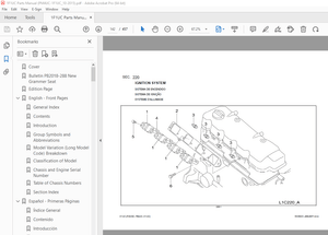
High Energy Ignition (HEI) System 453
Safety Precautions Maintenance and Repair 454
Description 457
Distributor Repair 459
Remove 459
Disassemble 459
Assemble 465
Install, If Crankshaft WAS NOT Rotated when Distributor was Remo 466
Install, If Crankshaft WAS Rotated when Distributor was Removed 466
Ignition Coil Replacement 468
Some Four- and Six-Cylinder Models 468
Remove 468
Install 468
V8, Some Four- and Six-Cylinder Models 469
Remove 469
Install 469
Electronic Module Replacement 470
Remove 470
Install 470
Sensing Coil Replacement 472
Remove 472
Install 472
Spark Plugs Replacement 472
Remove 472
Install 473
Visual Check 473
High Voltage Wires Check 473
Ignition Coil Check 474
Coil in Distributor Cap Design 474
Separate Coil Design 474
Sensing Coil, Check 475
Electronic Module Check 475
Ignition Timing Adjustment 476
GM V8-366 (6-liter) Ignition System Check 477
GM V6-LPG (4 3 liter) GM V6-LPG (4 3 liter) Ignition Timing and 477
Specifications 477
Troubleshooting 478
524153916 2200YRM0765 (03 2003) US EN 483
toc 483
Microprocessor Spark Timing System (MSTS) 483
Safety Precautions Maintenance and Repair 484
General 487
Description 488
What MSTS Does 488
How MSTS Begins Operation 488
Operation 489
Distributor 489
Ignition Coil 490
Ignition Module 490
When Engine Is Being Started 490
When Engine Is Running 492
Manifold Absolute Pressure (MAP) Sensor 493
Engine Coolant Temperature (ECT) Sensor 493
MSTS Module Corrections 494
Troubleshooting 495
General 495
Tools and Test Equipment 497
MSTS 498
Troubleshooting Procedure 498
Where to Start 498
Visual/Physical Inspection 498
Knowledge/Tools Required 498
Damage From Static Discharge (Static Electricity) 499
Troubleshooting Information 499
Malfunction Indicator Lamp (MIL) 499
Connecting CodeMate Tester 499
Reading Diagnostic Trouble Codes (DTC) 500
Clearing Diagnostic Trouble Codes (DTC’s) 501
On-Board Diagnostic (OBD) System Check 501
Test Description 501
No Malfunction Indicator Lamp 503
Circuit Description 503
Test Description 503
No DTC-12, Malfunction Indicator Lamp ON 505
Circuit Description 505
Test Description 505
Starter Rotates Engine, Engine Does Not Run 506
Test Description 506
DTC-14 Engine Coolant Temperature (ECT) (Low Temperature Indicat 510
Circuit Description 510
Test Description 510
DTC-15 Engine Coolant Temperature Sensor (ECT) (High Temperature 512
Circuit Description 512
Test Description 512
DTC-34 Manifold Absolute Pressure (MAP) Sensor 514
Circuit Description 514
Test Description 514
DTC-41 Electronic Spark Timing (EST) Open Circuit 517
Circuit Description 517
Test Description 517
DTC-42 Electronic Spark Timing (EST) Grounded Circuit 519
Circuit Description 519
Test Description 519
DTC-51 MSTS Failure 521
Circuit Description 521
Distributor Repair 521
Remove 521
Disassemble 522
Inspect 522
Assemble 522
Install 523
Ignition Timing 523
Ignition Module Repair 524
Test For Fault 524
Replace 524
Sensing Coil Repair 525
Test For Fault 525
Replace 525
Ignition Coil Repair 526
Test For Fault 526
Remove 526
Install 526
MSTS Module Repair 527
Remove 527
Install 527
ECT Sensor Replacement 527
MAP Sensor Replacement 528
tables 483
Table 1 MSTS Module Connections 496
Table 2 Pressure Conversion Chart 497
Table 3 MSTS Diagnostic Codes 499
524153917 2200YRM0781 (03 2003) US EN 531
toc 531
Electronic Engine Control 531
Safety Precautions Maintenance and Repair 532
General 535
Description and Operation 535
General 535
Electronic Control Module (ECM) 535
Diagnostic Connector 535
How ECM Begins Operation 539
Electronic Engine Control 540
What ECM Does 540
Distributor 542
Ignition Module 542
When Engine Is Being Started 543
When Engine Is Running 544
Electronic Control Module (ECM) with Ignition Module Distributor 544
Fuel Control 545
Throttle Body Injection (TBI) 546
Fuel Injectors 546
Fuel Pressure Regulator 546
Throttle Position Sensor (TPS) 547
Idle Air Control (IAC) 547
GM 4 3L Engine Governor System 548
GM 3 0L Engine Governor System 548
Vacuum Ports 550
Fuel Pump 550
ECM Sensors and Controllers 552
Manifold Absolute Pressure (MAP) 552
Engine Coolant Temperature (ECT) Sensor 552
524153918 2200YRM0782 (03 2003) US EN 555
toc 555
Electronic Engine Control 555
Safety Precautions Maintenance and Repair 556
General 561
Troubleshooting Procedure 561
How This Section Is Arranged 561
Where Do I Start? 561
Visual/Physical Inspection 561
Knowledge/Tools Required 561
Damage From Static Discharge (Static Electricity) 561
Troubleshooting Information 562
Malfunction Indicator Lamp (MIL) 562
Reading Diagnostic Trouble Codes (DTC) 562
Clearing Diagnostic Trouble Codes (DTCs) 566
ECM Diagnostic Codes Available 567
Diagnostic Mode 567
Field Service Mode 567
ECM Learning Ability 567
SCAN Tool Information 568
On-Board Diagnostic (OBD) System Check 569
Test Description 569
Troubleshooting Charts 571
General 571
Tools and Test Equipment 571
Troubleshooting Chart Description Summary 572
A-1 – No Malfunction Indicator Lamp 572
Circuit Description 572
Test Description 573
Other Troubleshooting Checks 573
A-2 – No Scan Data, No DTC 12, Malfunction Indicator Lamp ON 575
Circuit Description 575
Test Description 575
A-3 – Starter Rotates Engine, Engine Will Not Run 577
Circuit Description 577
Test Description 577
Other Troubleshooting Checks 577
A-4 – Fuel Injector Circuit 579
Test Description 579
A-5 – Fuel Pump Relay Circuit 581
Circuit Description 581
Test Description 581
Other Troubleshooting Checks 581
A-6 – Fuel System Troubleshooting 583
Circuit Description 583
Test Description 583
Other Troubleshooting Checks 583
Test Description 585
Fuel Pressure Check 587
A-7 – Ignition System Troubleshooting 587
Test Description 588
DTC 14 Engine Coolant Temperature Sensor Circuit (Low Temperatur 591
Circuit Description 591
Test Description 591
Other Troubleshooting Checks 591
DTC 15 Engine Coolant Temperature Sensor Circuit (High Temperatu 593
Circuit Description 593
Test Description 593
Other Troubleshooting Checks 593
DTC 21 Throttle Position Sensor Circuit (Signal Voltage High) 595
Circuit Description 595
Test Description 595
Other Troubleshooting Checks 595
DTC 22 Throttle Position Sensor Circuit (Signal Voltage Low) 597
Circuit Description 597
Test Description 597
Other Troubleshooting Checks 597
DTC 31 Engine Governor Circuit 599
Circuit Description 599
Test Description 599
Other Troubleshooting Checks 599
DTC 33 Manifold Absolute Pressure (MAP) Sensor Circuit (Signal V 601
Circuit Description 601
Test Description 601
Other Troubleshooting Checks 601
DTC 34 Manifold Absolute Pressure (MAP) Sensor Circuit (Signal V 603
Circuit Description 603
Test Description 603
Other Troubleshooting Checks 603
DTC 41 Electronic Spark Timing (EST) – Open EST Circuit 605
Circuit Description 605
Test Description 605
Other Troubleshooting Checks 605
DTC 42 EST – Grounded EST Circuit, Open or Grounded Bypass Circu 607
Circuit Description 607
Test Description 608
Other Troubleshooting Checks 608
DTC 51 ECM Failure 610
Circuit Description 610
Other Troubleshooting Checks 610
Troubleshooting, Poor Operation 611
General 611
Make a Careful Visual Check 611
FAULT: Codes or Performance That Is Not Regular 611
FAULT: Loss of Diagnostic Trouble Code (DTC) Memory 611
FAULT: Engine Quits While Driving 611
Additional Checks 611
FAULT: Engine Is Difficult to Start 611
FAULT: Variation in Engine Power When Throttle Is Held Steady 612
FAULT: Decreased Engine Power 612
FAULT: Detonation 613
FAULT: Engine Momentarily Does Not Increase Power When Throttle 613
FAULT: One or More Cylinders Do Not Operate Correctly – Engine D 614
FAULT: Rough Idle or Engine Stalls During Idle 614
FAULT: Fuel Usage Too High 614
FAULT: Dieseling 615
FAULT: Backfire 615
System Test Charts 615
General 615
Engine Coolant Temperature (ECT) Sensor Test 615
Throttle Position (TP) Sensor Check 616
Minimum Idle Speed 616
Adjustment 617
B-1 – Idle Air Control (IAC) System Check 618
Circuit Description 618
Other Troubleshooting Checks 618
B-2 – Manifold Absolute Pressure (MAP) Sensor Output Test 620
Circuit Description 620
Test Description 620
B-3 – Check Governor System 622
Governor System Not Operating Correctly 622
Check Function of Governor System 622
Check PCV System 623
Fuel System Components Repair 623
General 623
Fuel Pressure Relief Procedure 623
Fuel Pump Replacement 623
Throttle Body Injection Unit (TBI) 624
Remove 624
Clean and Inspect 625
Install 625
Fuel Meter Body 625
Remove 625
Install 628
Fuel Injector 628
Remove 628
Install 629
Pressure Regulator 629
Remove 629
Inspect 629
Install 629
Throttle Position Sensor (TPS) 630
Remove 630
Install 630
Idle Air Control (IAC) Valve 630
Remove 630
Clean and Inspect 630
Install 631
Governor System 3 0L Engine Repair 631
Governor Module, Replace 631
Governor Motor, Replace 631
Throttle Cables, Install and Adjust 631
Foot Directional Control Pedal, Check 632
Governor System 4 3L Engine Repair 633
Governor Throttle Drive Assembly 633
Remove 633
Inspect 634
Install 634
Governor Drive Motor 634
Remove 634
Clean and Lubricate 634
Install 635
Inspect 636
Ignition System Components Repair 636
ECM Replacement 636
Function Check 636
Distributor 636
Remove 636
Disassemble 636
Inspect 637
Assemble 637
Install 637
Firing Order 638
Ignition Timing 638
Ignition Module Repair 638
Test For Fault 638
Replace 639
Sensing Coil 639
Test 639
Replace 640
Ignition Coil 640
Test 640
Remove 640
Install 641
Sensors Repair 641
Engine Coolant Temperature (ECT) Sensor, Replace 641
MAP Sensor, Replace 641
PCV System Repair 642
Replace 642
Wiring 642
Connectors and Terminals 642
Procedures for Spark Plugs, Spark Plug Wires, and Boots 645
Wiring Diagram 645
Spark Plugs Troubleshooting 650
Special Tools 651
tables 555
Table 1 ECM Diagnostic Codes Available 567
Table 2 SCAN Tool Information 568
Table 3 Troubleshooting Chart Description Summary 572
Table 4 ECT Sensor – Temperature vs Resistance 593
Table 5 ECT Sensor – Temperature vs Resistance 616
Table 6 ECM Connector J1 Identification 648
Table 7 ECM Connector J2 Identification 649
524185155 0100YRM0322 (02 2007) US EN 655
toc 655
Frame 655
Safety Precautions Maintenance and Repair 656
General 659
Description 659
Counterweight Repair 660
Remove 660
Install 660
Hood Repair 661
Remove 661
Install 661
Overhead Guard Repair 661
Remove 661
Install 661
Operator Restraint System Repair 662
Automatic Locking Retractor (ALR) 662
Emergency Locking Retractor (ELR) 662
Hydraulic Tank Repair 664
Remove 664
Inspect 664
Small Leaks Repair 664
Large Leaks Repair 664
Clean 664
Steam Method 664
Chemical Solution Method 665
Other Methods of Preparation for Repair 665
Install 665
Fuel Tank Repair 666
Remove 666
Repair 666
Install 666
Radiator Repair 666
Remove 666
Install 666
Engine Repair 667
Remove 667
Install 667
Throttle Pedal Adjustment 669
Perkins 1104C-44(RE) Diesel Engine 669
Safety Labels 670
Cab Repair 672
Cab, Replace 672
Window, Replace 672
Windshield Wipers and Heater 672
tables 655
Table 1 Material Specifications for Cab Windows 672
524185156 1300YRM0324 (10 2003) US EN 677
toc 677
Two-Speed Powershift Transmission 677
Safety Precautions Maintenance and Repair 678
General 681
Mechanical Description 681
Torque Converter 681
Transmission Pump 682
Shaft Assemblies 682
Input Shaft 683
Forward Clutch Shaft 683
Clutch Assemblies 683
Countershaft 690
Output Shaft 690
Hydraulic Operation 691
Torque Converter 691
Seal Rings 692
Control Valve 692
System Pressure Regulator 695
Clutch Pressure Regulator 695
Torque Converter Regulator 696
Inching Spool 696
Direction Spool, Direction Control Lever 696
Direction Spool, Foot Directional Control Pedal 697
Range Spool 698
Drain Spool 698
Accumulator 698
Modulator Spool 698
Operation 699
Lubrication Circuit 699
Foot Directional Control Pedal 700
Oil Flow Diagrams 701
Neutral 701
Forward-Low 701
Forward-Low-Inching 701
Reverse-Low 702
524185157 1300YRM0325 (10 2003) US EN 709
toc 709
Two-Speed Powershift Transmission 709
Safety Precautions Maintenance and Repair 710
General 713
Transmission Repair 713
Transmission and Torque Converter, Remove 713
Transmission, Disassemble 715
Reverse-Low Clutch, Disassemble 718
Reverse-High Clutch, Disassemble 721
Forward-Low Clutch, Disassemble 724
Forward-High Clutch, Disassemble 727
Clean and Inspect 729
Forward Low and High Clutches Assembly 730
Forward Clutches, Assemble 732
Reverse-Low Clutch, Assemble 738
Reverse Clutches, Assemble 740
Transmission, Assemble 747
Torque Converter, Install 753
Control Valve Repair 754
Remove 754
Disassemble 755
Assemble 756
Install 758
Foot Directional Control Pedal 758
Remove and Disassemble 758
Assemble and Install 758
Stall Test 761
Linkage Adjustments 762
Linkage for Inching Pedal GDP60-70CA (GP/GLP/GDP135-155CA) (A878 762
Linkage for Inching Pedal GC/GLC/GDC135-155CA (A879, B879) 765
Linkage for Range Lever – Early Model GDP60-70CA (GP/GLP/GDP135- 767
Linkage for Direction Control Lever – Early Model GDP60-70CA (GP 769
Linkage for Range Lever – Later Model GDP60-70CA (GP\GLP\GDP135- 769
Linkage for Direction Control Lever – Later Model GDP60-70CA (GP 771
Linkage for Range Lever GC/GLC/GDC135-155CA (A879, B879) 773
Linkage for Direction Control Lever GC/GLC/GDC135-155CA (A879, B 773
Oil Pressure Check 775
System Pressure Check Port 776
Torque Converter Check Port 776
Clutch Pressure Check Port 776
Inching Pressure 776
Solenoid Check Ports ( Foot Directional Control Only) 776
Lubrication Pressure Check Ports 776
Specifications 776
Troubleshooting 777
Correct System Pressure: 1300 ±124 kPa ( 189 ±18 psi) 779
Correct Clutch Pressure: 924 ±69 kPa ( 134 ±10 psi) 780
Correct Solenoid Pressure (Foot Directional Control Only): 965 ± 781
Torque Converter Pressure: 834 ±69 kPa ( 121 ±10 psi) 781
Lubrication Pressure: 83 ±21 kPa ( 12 ±3 psi) 782
tables 709
Table 1 Stall Speed Specifications 761
524185158 1300YRM0344 (03 2003) US EN 785
toc 785
Speed Reducer 785
Safety Precautions Maintenance and Repair 786
General 789
Description 789
Operation 789
Speed Reducer Repair 789
Remove 789
Disassemble 789
Clean and Inspect 792
Assemble 792
Install 793
Direction Control Linkage Adjustment 794
524185159 1400YRM0049 (09 2003) US EN 797
toc 797
Drive Axle 797
Safety Precautions Maintenance and Repair 798
General 801
Description 801
Drive Axle Repair 802
Disassemble 802
Clean 805
Inspect 805
Assemble 806
Torque Specifications 809
Troubleshooting 809
524185160 1600YRM0054 (10 2003) US EN 813
toc 813
Steering Control Unit 813
Safety Precautions Maintenance and Repair 814
General 817
Description 817
Operation 817
Steering Wheel and Column Assembly Repair 819
Steering Column Assembly Repair 819
Type A Steering Column Assembly 819
Remove and Disassemble 819
Assemble and Install 821
Type B Steering Column Assembly 823
Remove and Disassemble 823
Assemble and Install 823
Steering Control Unit 826
Disassemble 826
Clean 829
Assemble 830
System Air Removal 835
Troubleshooting 835
524185161 1800YRM0327 (09 2003) US EN 839
toc 839
Brake System 839
Safety Precautions Maintenance and Repair 840
General 843
Description 843
Operation 844
Brake Booster and Master Cylinder 844
Brake Booster 844
Master Cylinder 845
Service Brake Assembly 846
Parking Brake 847
Brake Shoe Assemblies Repair 848
Remove and Disassemble 848
Clean and Inspect 848
Cleaning Procedures 848
Inspect 848
Assemble and Install 850
Master Cylinder Repair 851
Remove 851
Disassemble 851
Assemble 853
Install 853
Brake Booster Repair 853
Remove 853
Disassemble 853
Clean and Inspect 855
Assemble 855
Install 855
Brake System Air Removal 855
Brake Pedal Adjustment 856
Brake Shoes Adjustment 857
Parking Brake Adjustment 857
Parking Brake Switch Adjustment 857
Brake Booster Relief Valve Check 857
Troubleshooting 858
524185163 1900YRM0328 (09 2003) US EN 863
toc 863
Hydraulic System 863
Safety Precautions Maintenance and Repair 864
General 867
Description and Operation 867
Hydraulic Pumps 868
Main Control Valve 869
Control Valve Lever 869
Steering Control Unit 869
Brake Valve 870
Troubleshooting 870
Lift, Lower, and Tilt Circuit 871
Steering and Brake System 872
524185164 2000YRM0090 (10 2003) US EN 877
toc 877
Main Control Valve 877
Safety Precautions Maintenance and Repair 878
General 881
Description 881
Operation 881
Lift Spool 881
Tilt Spool 881
Tilt Backward 881
Tilt Forward 885
Two-Stage Relief Valve 886
Main Control Valve Repair 887
Remove and Disassemble 887
Clean and Inspect 887
Assemble 887
Install 888
Two-Stage Relief Valve 888
Troubleshooting 889
tables 877
Table 1 Relief Pressures (Oil temperature at 55 to 66 C ( 131 t 888
524185165 2200YRM0143 (02 2007) US EN 893
toc 893
Instrument Panel Indicators and Senders 893
Safety Precautions Maintenance and Repair 894
General 897
Description 898
Internal Combustion Engine Trucks 898
Instrument Cluster Panels at Base of Steering Column, Descriptio 903
Trucks With Instrument Cluster Display Panels, Description 904
Electric Lift Trucks 907
Battery Gauge With Lift Interrupt (Curtis 933/1 and 933/4 Models 908
Battery Gauge With Lift Interrupt and Brush Wear Indicator (GE), 908
EV-100LX Motor Controller Display Panel (ITW), Description 909
Adjustments – General 910
Replacement – General Information 910
Internal Combustion Engine Display Panel Replacement 910
Display Panels Mounted at Base of Steering Column 910
Remove 910
Install 912
Instrument Cluster Display Panels Mounted on Cowl 912
Remove and Install 912
Inner Components, Replace 912
Electric Truck Display Panel Replacement 914
GE and Curtis 933/1 and 933/4 Battery Gauges 914
Controller for Battery Indicator, Replace 914
ITW Display Panel, Replace 914
Remove 914
Sender Replacement 918
Fuel Level Sender 918
Pressure and Temperature Sender 918
Seat Sensor, Operator Presence System (OPS) 919
Remove 919
Install 919
Operator Presence System Module Replacement 919
Remove 919
Install 921
Specifications 922
Meter Specifications 922
Sender Specifications 923
Troubleshooting 924
Meter 924
Troubleshooting for Operator Presence System 925
tables 893
Table 1 Troubleshooting Procedure for Operator Presence Module 925
524185167 4000YRM0329 (09 2010) US EN 931
toc 931
Masts 931
Safety Precautions Maintenance and Repair 932
General 935
Description and Operation 935
General 935
Safety Procedures When Working Near Mast 936
Two-Stage Mast 938
Three-Stage Mast 939
Carriage Repair 940
Remove 940
Sideshift Carriage, Disassemble 942
Sideshift Carriage, Assemble 944
Install 944
Two-Stage Mast Repair 945
Remove 945
Disassemble 947
Clean and Inspect 947
Assemble 948
Install 949
Three-Stage Mast Repair 950
Remove 950
Disassemble 950
Clean and Inspect 951
Assemble 951
Install 952
Mast Operation Check 953
Lift and Tilt System Leaks Check 953
Lift System 953
Tilt System 954
Tilt Cylinder Stroke and Backward Tilt Angle Adjustment 954
Lift Chain Adjustments 955
Mast Adjustments 957
Carriage Adjustment 959
Troubleshooting 960
tables 931
Table 1 Mast Parts Weight 945
Table 2 Hook-Type Carriage Chain Adjustment 956
Table 3 Pin-Type Carriage Chain Adjustment 956
524185168 8000YRM0331 (09 2003) US EN 965
toc 965
Capacities and Specifications 965
Safety Precautions Maintenance and Repair 966
Lift Truck Weights 969
Capacities 969
Tire Sizes 970
Tire Pressure 970
Electrical System 970
Wheel Nut Torque 970
Engine Specifications 971
Hydraulic System 971
Mast Speeds 972
Transmission Oil Pressures 972
Torque Specifications 973
Engine – GM 4 3L V-6 973
Engine – Perkins 1004 4 973
Clutch 973
Manual Transmission 973
Powershift Transmission 973
Speed Reducer 974
Drive Axle 974
Steering System 974
Brake System 974
Hydraulic System 974
Tilt Cylinder 974
Mast 974
524185169 8000YRM0341 (06 2009) US EN 977
toc 977
Periodic Maintenance 977
Safety Precautions Maintenance and Repair 978
General 983
Serial Number Data 983
How to Move Disabled Truck 983
How to Tow Lift Truck 983
How to Put Lift Truck on Blocks 984
How to Raise Drive Tires 984
How to Raise Steering Tires 984
Maintenance Schedule 985
Maintenance Procedures Every 8 Hours or Daily 996
How to Make Checks With Engine Stopped 996
Hydraulic System Oil 996
Engine Oil 997
Drive Belts 997
Intake Manifold Rubber Cap 998
Cooling System 998
Air Filter 998
Fuel System 999
Primary Fuel Filter, Diesel Engine 999
Battery 999
Tires and Wheels 1000
Forks 1000
Adjust 1000
Remove and Install 1002
Forks, Mast, and Lift Chains, Inspect 1003
Operator Restraint System 1004
Automatic Locking Retractor (ALR) 1004
Emergency Locking Retractor (ELR) 1004
Safety Labels 1005
How to Make Checks With Engine Running 1006
Gauges, Lights, Horn, and Fuses 1006
Oil Level, Powershift Transmission 1007
Oil Level, Oil Clutch System, GP/GLP/GDP070-110LG/MG 1008
Control Levers and Pedals 1008
Lift System Operation 1008
Inching/Brake Pedal 1008
Service Brakes 1008
Parking Brake 1009
Steering System 1009
Maintenance Procedures Every 250 Hours or 6 Weeks 1009
Engine Oil and Filter, GM V-6 Engine 1009
Lift Chains, Lubrication 1009
Drive Shafts 1009
Mast Lubrication 1010
Crankcase Breather, GM V-6 1010
Air Filter, GM V-6 EPA Compliant Engine 1010
Maintenance Procedures Every 350 Hours or 2 Months 1011
Drive Belts 1011
Perkins Diesel Engine 1011
GM V-6 Engine (Early Models) 1012
GM V-6 Engine (Late Models) 1012
Brake Fluid 1014
Lift Chains Wear Check 1014
Forks Wear and Damage Check 1014
Steering Axle Lubrication 1014
Fuel System, Checks and Adjustments 1015
Diesel Fuel System 1015
LPG Carburetor (Early Models) 1015
Gasoline Carburetor (Early Models) 1016
Fuel Injection (Late Models) 1016
Hydraulic Tank Breather 1016
Cooling System, Clean Debris from Radiator Core 1016
Maintenance Procedures Every 500 Hours or 3 Months 1017
Engine Oil and Filter, Perkins Diesel Engine 1017
Crankcase Breather, Perkins Diesel Engine 1017
PCV Valve, GM V-6 1017
Maintenance Procedures Every 1000 Hours or 6 Months 1017
Manifold Heat Valve, GM V-6 (Early Models) 1017
Ignition System, GM V-6 1017
Valve Clearance Adjustment 1017
Fuel Filter, Replace (Diesel Engine) 1018
Fuel System Air Removal (Perkins 1004-4 Diesel Engine) 1018
Fuel Injection Pump With Vent Tube 1018
Fuel Injection Pump With Vent Screw 1019
Oil Level Check in Transmission 1021
Manual Transmission, GP/GLP/GDP070-110LG/MG 1021
Speed Reducer for Powershift Transmission, GP/GLP/GDP070-110LG/M 1021
Manual Transmission, GDP60-70CA (GP/GLP/GDP135-155CA) 1021
Differential and Drive Axle for Powershift Transmission, GDP60-7 1021
Differential, Speed Reducer, and Drive Axle for Manual Transmiss 1021
Control Levers and Pedals, Lubricate 1021
Crankcase Breather, Replace 1021
Cooling System, GM V-6 EPA Compliant Engine 1021
Spark Plug Replacement 1022
Remove 1022
Install 1022
LPG Fuel Filter GM V-6 EPA Compliant Engine, Replace 1022
Inspect Engine Electrical System, Connectors, and FCVS Connectio 1023
Maintenance Procedures Every 2000 Hours or Yearly 1024
Hydraulic System 1024
Hydraulic Oil and Filter, GP/GLP/GDP070-110LG/MG, Replace 1024
Hydraulic Oil and Filter, GDP60-70CA (GP/GLP/GDP135-155CA), Repl 1024
Oil Change and Oil Filter Replacement, Powershift Transmission, 1024
Oil Change, Manual Transmission, GP/GLP/GDP070-110LG/MG 1025
Oil Change, Manual Transmission, GDP60-70CA (GP/GLP/GDP135-155CA 1025
Oil Change, Speed Reducer, Powershift Transmission, GP/GLP/GDP07 1025
Oil and Filter Change, Oil Clutch System, GP/GLP/GDP070-110LG/MG 1025
Oil Change, Differential and Drive Axle, Powershift Transmission 1025
Oil Change, Differential, Speed Reducer, and Drive Axle, Manual 1026
Cooling System 1026
PCV Valve, GM V-6 1026
Service Brakes 1026
LPG Filter, Replace 1027
Gasoline Fuel Filter, Replace 1027
Hood Latch Check, GP/GLP/GDP070-110LG/MG 1027
Air Filter Element, GM V-6 EPA Compliant Engine 1028
Oxygen Sensor GM V-6 EPA Compliant Engine 1028
Inspect Low Pressure Regulator (LPR) for Oil Buildup and Leaks 1028
Check Throttle Shaft for Sticking 1029
Inspect Exhaust Manifold and Piping for Leaks 1029
Test LPG/GAS Regulator Pressure 1029
Safety Procedures When Working Near Mast 1029
Lift Chain Adjustments 1032
Fuel Injectors Repair 1034
Lift and Tilt System Leak Check 1034
Lift Cylinders, Leak Check 1034
Tilt Cylinders, Leak Check 1035
Welding Repairs 1035
Overhead Guard Changes 1036
Wheel and Tire Replacement 1037
Remove Wheels From Lift Truck 1037
Remove Wheels From Tire 1037
Remove Tire From Two-Piece Wheel 1038
Remove Tire From Three- and Four-Piece Wheels 1040
Install Wheel in Tire 1042
Install Three- or Four-Piece Wheel in Tire 1042
Install Two-Piece Wheel in Tire 1044
Add Air to Pneumatic Tires 1045
Wheels, Install 1045
Solid Rubber Tires Repair 1046
Wheel, Tire Remove 1046
Wheel, Tire Install 1048
SIT Tire, Change for GDP60-70CA (A878, and B878), and GP/GLP/GDP 1050
Remove SIT Solid Tire From Wheel 1050
Install SIT Solid Tire on Wheel 1051
Adhesives and Sealants 1052
Hydraulic Oil, Lubricant, and Coolant Specifications 1052
tables 977
Table 1 Maintenance Schedule 986
Table 2 Hook-Type Carriage Chain Adjustment 1032
Table 3 Pin-Type Carriage Chain Adjustment 1033
524185171 8000YRM0519 (06 2007) US EN 1055
toc 1055
Diagrams 1055
Safety Precautions Maintenance and Repair 1056
More products