$41.95
Yale Forklift A878 (GPGDPGLP135-155CA) Service Manual – PDF DOWNLOAD
Yale Forklift A878 (GPGDPGLP135-155CA) Service Manual – PDF DOWNLOAD
FILE DETAILS:
Yale Forklift A878 (GPGDPGLP135-155CA) Service Manual – PDF DOWNLOAD
Language : English
Pages : 1110
Downloadable : Yes
File Type : PDF
IMAGES PREVIEW OF THE MANUAL:

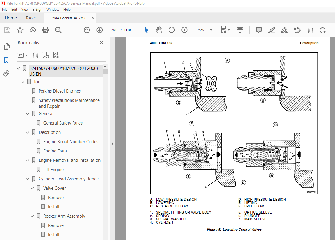
TABLE OF CONTENTS:
Yale Forklift A878 (GPGDPGLP135-155CA) Service Manual – PDF DOWNLOAD
524150774 0600YRM0705 (03 2006) US EN 1
toc 1
Perkins Diesel Engines 1
Safety Precautions Maintenance and Repair 2
General 9
General Safety Rules 9
Description 10
Engine Serial Number Codes 13
Engine Data 13
Engine Removal and Installation 15
Lift Engine 15
Cylinder Head Assembly Repair 15
Valve Cover 15
Remove 15
Install 16
Rocker Arm Assembly 16
Remove 16
Install 16
Disassemble 16
Inspect 17
Assemble 17
Valve Clearance Adjustments 17
Four-Cylinder Engines 18
Six-Cylinder Engines 18
Valve Springs 18
Cylinder Head Assembly 20
Remove 20
Install 22
Valves and Valve Springs 26
Remove 26
Inspect 26
Install 27
Valve Guides 27
Inspect 27
Remove 28
Install 28
Cylinder Head and Valve Seats 28
Inspect 28
Repair 28
New Valve Seats, Install 28
Piston and Connecting Rod Assemblies Repair 30
Rod Bearings 30
Remove 31
Install 31
Piston and Connecting Rod Assembly 32
Service Note 32
Remove 32
Install 33
Piston Rings 34
Remove 34
Inspect 34
Install 34
Piston and Connecting Rod 35
Disassemble 35
Inspect 36
How to Select Correct Replacements 36
Install 37
Piston Cooling Jets 37
Remove 37
Install 38
Crankshaft Assembly Repair 38
General 38
Crankshaft Pulley 39
Engine AR, Remove 39
Engines YG and YH, Remove 39
Inspect 40
Engine AR, Install 40
Engines YG and YH, Install 40
Rear Oil Seal 41
Replace 41
Main Bearings 42
Remove 42
Inspect 43
Install 43
Thrust Washers 43
Crankshaft Axial Movement, Check 43
Remove 44
Install 44
Crankshaft 45
Remove 45
Inspect 45
Install 45
Flywheel 47
Remove 47
Ring Gear, Replace 47
Install 47
Flywheel Housing 48
Remove 48
Install 48
Timing Case and Timing Gears Repair 49
General 49
Timing Case Cover 49
Remove 49
Install 50
Front Oil Seal 50
Remove 50
Install 50
Crankshaft Pulley Wear Sleeve 51
Install 51
Idler Gear and Hub 51
Remove 51
Install 52
Air Compressor Drive, Bendix 53
Disassemble 53
Assemble 54
Fuel Injection Pump Gear 54
Remove 55
Install 55
Camshaft Gear 56
Remove 56
Install 56
Crankshaft Gear 57
Remove 57
Install 57
Timing Case 57
Remove 57
Install 58
Camshaft and Tappets 59
Remove 59
Install 59
Cylinder Block Assembly Repair 60
Description 60
Cylinder Block 60
Disassemble 60
Inspect 61
Assemble 61
Cylinder Bore (Four-Cylinder Engines) 61
Cylinder Liner (Six-Cylinder Engines) 62
Inspect 62
Cylinder Liner Condition, Check 62
Remove 63
Service Liner, Install 63
Partially Finished Liner, Install 65
Engine Timing 65
Description 65
How to Set Number One Piston to TDC on Compression Stroke 67
How to Set Number One Piston to TDC on Compression Stroke (Alter 67
Valve Timing, Check 68
Fuel Injection Pump Timing, Check 69
Turbocharger – Engine YH Repair 70
General 70
Remove 70
Install 70
Impeller and Compressor Housing, Clean 71
Lubrication System Repair 72
General 72
Oil Filter, Replace 72
Filter Head 72
Remove and Install 72
Oil Sump 73
Remove 73
Install 73
Oil Pump 73
Remove 73
Inspect 74
Install 75
Relief Valve 75
Remove 75
Disassemble 76
Inspect 76
Assemble 76
Install 76
Idler Gear Shaft, Replace 77
Remove 77
Remove (Alternative) 77
Install 78
Install (Alternative) 78
Install (Alternative for Four-Cylinder Engines Only) 79
Fuel System Repair 79
Description 79
Fuel Injection Pump 80
Remove 80
Install 81
Check and Adjust 81
Fuel System Air Removal 82
Fuel Filter, Replace 83
Canister Type 83
Quick Release Canister Type 84
Fuel Injectors 85
Remove 85
Inspect 85
Install 85
Fuel Pump 86
Remove 86
Disassemble 86
Assemble 87
Install 88
Test 88
Cooling System Repair 88
General 88
Thermostat 88
Remove 88
Install 89
Test 89
Coolant Pump 89
Remove 89
Disassemble 90
Assemble 91
Install 94
Fan and Fan Drive 94
Remove 94
Install 95
Oil Cooler (Six-Cylinder Engines) 95
Remove 95
Disassemble and Assemble 95
Install 96
Oil Cooler Bypass Valve 96
Electrical Equipment Repair 96
Drive Belts 96
Adjustment 96
Remove 97
Install 97
Alternator 97
Remove 97
Install 97
Starter Motor 98
Remove 98
Install 98
Cold Start Aid 98
Air Compressor – Engines YG and YH 98
General 98
Repair 98
Remove 98
Install 99
Rotary Exhauster Replacement 100
Remove 100
Clean 100
Install 100
Engine Specifications 101
Cylinder Head Assembly 101
Piston and Connecting Rods 104
Crankshaft Assembly 107
Crankshaft Overhaul 108
Timing Case and Drive Assembly 110
Engine Block Assembly 111
Turbocharger 114
Lubrication System 114
Fuel System 115
Cooling System 117
Flywheel and Housing 117
Electrical Equipment 118
Torque Specifications 118
Cylinder Head Assembly 118
Piston and Connecting Rod Assemblies 118
Crankshaft Assembly 118
Timing Case and Drive Assembly 119
Turbocharger 119
Lubrication System 119
Fuel System 119
Cooling System 119
Flywheel 119
Auxiliary Equipment 119
Special Torque Specifications 120
Flywheel and Housing 120
Turbocharger 120
Electrical Equipment 120
Auxiliary Equipment 120
Special Tools* 121
Troubleshooting 126
tables 1
Table 1 Cylinder Head 101
Table 2 Valve Guides 101
Table 3 Inlet Valves 101
Table 4 Exhaust Valves 102
Table 5 Valve Springs 104
Table 6 Tappets 104
Table 7 Rocker Arm Shaft 104
Table 8 Rocker Arms and Bushings 104
Table 9 Pistons (Engine AR) 104
Table 10 Pistons (Engines YG and YH) 104
Table 11 Piston Rings (Engine AR) 105
Table 12 Piston Rings (Engines YG and YH) 105
Table 13 Piston Pins 106
Table 14 Connecting Rods 106
Table 15 Small End Bushings 106
Table 16 Connecting Rod Bearings (Engines AR and YG) 106
Table 17 Connecting Rod Bearings (Engine YH) 106
Table 18 Piston Cooling Jets 107
Table 19 Crankshaft 107
Table 20 Main Bearings 107
Table 21 Crankshaft Thrust Washers 107
Table 22 Crankshaft Heat Treatment 108
Table 23 Crankshaft Overhaul Specifications 108
Table 24 Maximum Variation (Run-out) 110
Table 25 Camshaft 110
Table 26 Camshaft Thrust Washer 110
Table 27 Camshaft Gear 110
Table 28 Gear for Fuel Injection Pump 111
Table 29 Crankshaft Gear 111
Table 30 Idler Gear and Hub 111
Table 31 Cylinder Block (Engine AR) 111
Table 32 Cylinder Bore Specifications 112
Table 33 Cylinder Block (Engines YG and YH) 113
Table 34 Cylinder Liners (Engines YG and YH) 113
Table 35 Cylinder Liner Specifications (Partially Finished) 113
Table 36 Oil Pump (Engine AR) 114
Table 37 Oil Pump (Engines YG and YH) 114
Table 38 Idler Gear for Oil Pump 114
Table 39 Relief Valve 115
Table 40 Oil Filter 115
Table 41 Lucas Fuel Injection Pump 115
Table 42 Fuel Injector Codes 116
Table 43 Fuel Pump (Engine AR) 117
Table 44 Fuel Pump (Engines YG and YH) 117
Table 45 Fuel Filter 117
Table 46 Coolant Pump 117
Table 47 Thermostat 117
Table 48 Fan Drive Housing 117
Table 49 Limits for Flywheel Run Out and Alignment (Total Indic 117
Table 50 Alternator 118
Table 51 Starter Motor 118
Table 52 Cold Start Aid 118
Table 53 List of Possible Causes 126
524150775 0700YRM0626 (03 2003) US EN 131
toc 131
Cooling System 131
Safety Precautions Maintenance and Repair 132
General 135
Description 136
Radiator 136
Radiator Cap 136
Thermostat 136
Water Pump 137
Fan and Fan Shroud 137
Cooling System Checks 137
Radiator 137
Thermostat 137
Water Pump 138
Exhaust Leaks 138
Fan and Fan Shroud 138
Radiator Cleaning 138
Drain 138
Clean 138
Fill 139
Troubleshooting 140
524150779 1400YRM0046 (08 2012) US EN 143
toc 143
Differential 143
Safety Precautions Maintenance and Repair 144
General 147
Description 147
Differential Repair 147
Remove 147
Differential Carrier From Axle Housing, Remove 147
Differential and Ring Gear From Differential Carrier, Remove 151
Drive Pinion and Pinion Carrier From Differential Carrier, Remov 153
Disassemble 154
Differential and Ring Gear Assembly, Disassemble 154
Drive Pinion and Pinion Carrier, Disassemble 155
Clean and Inspect 158
Assemble 159
Pinion, Bearings, and Pinion Carrier, Assemble 159
Pinion Bearings, Adjust Preload 159
Press Method 159
Yoke or Flange Method 160
Triple-Lip Seal, Install 161
Pinion Carrier Shim Set, Adjust Thickness (Depth of Pinion) 162
Differential and Ring Gear, Assemble 164
Differential Gears Rotating Torque, Check 166
Differential and Ring Gear Assembly, Install 167
Differential Bearings, Preload Adjust 168
Ring Gear, Runout Check 169
Ring Gear Backlash, Adjust 170
Gear Set, Tooth Contact Pattern Check 172
Thrust Screw, Install and Adjust 175
Install 175
Differential Assembly Into Axle Housing, Install 175
Specifications 176
Troubleshooting 180
tables 143
Table 1 Ring Gear Backlash Adjustment Specifications 171
Table 2 Ring and Pinion Tooth Contact Adjustment 172
Table 3 General Specifications 176
Table 4 Rivet Installation Pressure 176
Table 5 Pinion Adjustment 176
Table 6 Pinion Preload Pressure 177
Table 7 Torque Specifications 178
Table 8 Torque Specifications for Metric Hardware 179
Table 9 Torque Specifications for Metric (Fine) Hardware 179
524150783 1600YRM0326 (03 2007) US EN 183
toc 183
Steering Axle 183
Safety Precautions Maintenance and Repair 184
General 187
Description 187
Steering Axle Assembly Repair 192
Steering Axle GP/GLP/GDP070-110LG/MG (B813), GC/GLC070-120LG/MG 192
Remove 192
Install 192
Steering Axle GDP60-70CA (GP/GLP/GDP135-155CA) (A878, B878), GLP 193
Remove 193
Install 193
Wheels and Hubs Repair (All Units) 194
Remove and Disassemble 194
Clean 194
Inspect 194
Assemble and Install 194
Spindles and Bearings Repair (All Units) 196
Remove 196
Clean 196
Assemble and Install 197
Tie Rods Repair (All Units) 198
Remove 198
Clean 198
Install 198
Steering Cylinder Repair 201
Remove and Disassemble 201
Clean and Inspect 201
Assemble and Install 201
Troubleshooting 202
524150790 2100YRM0103 (03 2007) US EN 207
toc 207
Tilt Cylinders 207
Safety Precautions Maintenance and Repair 208
General 211
Description 211
Tilt Cylinder Repair 211
Remove 211
Disassemble 211
Clean 211
Assemble 212
Tilt Cylinders With O-Ring or Single-Lip Seals 212
Tilt Cylinders 213
Install 214
Tilt Cylinder Leak Check 216
Tilt Cylinder Stroke and Mast Tilt Angle Adjustment 217
Torque Specifications 217
Piston Rod Nut 217
Retainer 217
Troubleshooting 218
tables 207
Table 1 Movement Rates (Maximum) for Tilt Cylinders 216
524150791 2200YRM0002 (01 2016) US EN 223
General 227
Description 228
Alternator Repair 230
Alternator Type A 230
Remove and Disassemble 230
Clean 232
Assemble 232
Install 233
Alternator Type B 236
Remove and Disassemble 236
Clean 236
Assemble 237
Install 238
General Check and Adjustment 238
Low Output Check (Type A or Type B) 239
High Output Check (Type A or Type B) 242
Brushes Circuit Check 243
Delco Alternators 243
Motorola Alternators 243
Diodes Check 244
Diode Bridge Check 244
Delco and Leece-Neville Alternators 244
Motorola Alternators 244
Rotor Field Winding Check 245
Stator Windings Check 246
Voltage Regulator Check 246
Troubleshooting 246
524150792 2200YRM0106 (01 2016) US EN 251
General 255
Description and Operation 256
Starter Repair 260
Remove 260
Disassemble 260
Clean 261
Assemble 261
Install 262
General Checks and Adjustments 262
Troubleshooting 264
524150794 4000YRM0135 (03 2011) US EN 271
toc 271
Lift Cylinders 271
Safety Precautions Maintenance and Repair 272
Safety Procedures When Working Near Mast 275
General 279
Description 279
Lowering Control Valve 279
Cylinders (General) 282
Lift Cylinder Repair 282
Lift Cylinder Removal Without Removing Mast 282
Standard Masts With Main Lift Cylinder Fastened to Crossmember o 282
Standard and Full Free-Lift Masts With Lift Cylinder Fastened to 283
Masts That Have Two Cylinders, Main Lift Cylinder and Free-Lift 284
Disassemble 284
Assemble 284
Lift Cylinder Installation in Mast 286
Standard Masts With Main Lift Cylinder Fastened to Crossmember o 286
Standard and Full Free-Lift Masts With Lift Cylinder Fastened to 286
Chevron-Style Packing 287
Chevron-Style Packing Installation on Piston 287
Chevron-Style Packing Installation in Packing Gland 289
Lift Cylinders for HI VIS® Masts 291
Description 291
Lowering Control Valve 291
Remove 293
Disassemble 294
Assemble 294
Install 296
Main Lift Cylinders 296
Free-Lift Cylinder 296
Lift System Leak Check 296
Specifications 297
Troubleshooting 298
tables 271
Table 1 Cylinder Retainer Torque Specifications and Weight Guid 297
524150797 8000YRM0231 (03 2020) US EN 303
General 307
Threaded Fasteners 307
Nomenclature, Threads 307
Strength Identification 308
Cotter (Split) Pins 309
Fastener Torque Tables 314
Conversion Table 316
524153897 0600YRM0590 (04 2014) US EN 323
524153900 0900YRM0348 (03 2003) US EN 375
toc 375
LPG Fuel System 375
Safety Precautions Maintenance and Repair 376
General 379
Description and Operation 380
Fuel Tank 380
Fuel Filter and Fuel Valve Unit 381
Vaporizer 382
Carburetor 383
Governor 385
LPG Tank Repair 386
Remove 386
LPG Tanks With Fixed Mounting Bracket 386
LPG Tanks With EZ Lift Mounting Bracket 386
Install 387
LPG Tanks With Fixed Mounting Bracket 387
Hydrostatic Relief Valve Repair 388
Remove and Install 388
Filter Unit Repair 389
Fuel Filter Element, Replace 389
Diaphragm and Fuel Valve, Replace 389
Hoses Replacement 391
Vaporizer Repair 391
Remove 391
Disassemble 391
Clean 391
Inspect 391
Assemble 393
Install 396
Carburetor Repair 397
Remove 397
Disassemble 397
Clean 397
Assemble 397
Install 397
Governor Repair 398
Filter Unit Check 400
Vaporizer Check 400
Pressure Reducer Valve 400
Vapor Valve 400
Carburetor Adjustment 400
Idle Mixture 400
Idle Speed 400
Power Mixture 400
Throttle Linkage Adjustment 401
Adjustment For Models GDP60-70CA (GP/GLP/GDP135-155CA), GC/GLC07 401
Adjustment For Models GC070-120LJ/MJ 401
Troubleshooting 402
524153907 1900YRM0097 (05 2012) US EN 409
toc 409
Hydraulic Gear Pumps 409
Safety Precautions Maintenance and Repair 410
Description 413
Operation 414
Flow Control Valve 414
Relief Valve 414
Hydraulic Gear Pump Repair 415
Remove 415
Disassemble 416
Clean 416
Inspect 417
Assemble 420
Install 422
Pump Output Check 422
Method No 1 422
Method No 2 423
Hydraulic System Air Check 424
Troubleshooting 425
524153914 2200YRM0107 (03 2008) US EN 431
toc 431
High Energy Ignition (HEI) System 431
Safety Precautions Maintenance and Repair 432
Description 435
Distributor Repair 437
Remove 437
Disassemble 437
Assemble 443
Install, If Crankshaft WAS NOT Rotated when Distributor was Remo 444
Install, If Crankshaft WAS Rotated when Distributor was Removed 444
Ignition Coil Replacement 446
Some Four- and Six-Cylinder Models 446
Remove 446
Install 446
V8, Some Four- and Six-Cylinder Models 447
Remove 447
Install 447
Electronic Module Replacement 448
Remove 448
Install 448
Sensing Coil Replacement 450
Remove 450
Install 450
Spark Plugs Replacement 450
Remove 450
Install 451
Visual Check 451
High Voltage Wires Check 451
Ignition Coil Check 452
Coil in Distributor Cap Design 452
Separate Coil Design 452
Sensing Coil, Check 453
Electronic Module Check 453
Ignition Timing Adjustment 454
GM V8-366 (6-liter) Ignition System Check 455
GM V6-LPG (4 3 liter) GM V6-LPG (4 3 liter) Ignition Timing and 455
Specifications 455
Troubleshooting 456
524153916 2200YRM0765 (03 2003) US EN 461
toc 461
Microprocessor Spark Timing System (MSTS) 461
Safety Precautions Maintenance and Repair 462
General 465
Description 466
What MSTS Does 466
How MSTS Begins Operation 466
Operation 467
Distributor 467
Ignition Coil 468
Ignition Module 468
When Engine Is Being Started 468
When Engine Is Running 470
Manifold Absolute Pressure (MAP) Sensor 471
Engine Coolant Temperature (ECT) Sensor 471
MSTS Module Corrections 472
Troubleshooting 473
General 473
Tools and Test Equipment 475
MSTS 476
Troubleshooting Procedure 476
Where to Start 476
Visual/Physical Inspection 476
Knowledge/Tools Required 476
Damage From Static Discharge (Static Electricity) 477
Troubleshooting Information 477
Malfunction Indicator Lamp (MIL) 477
Connecting CodeMate Tester 477
Reading Diagnostic Trouble Codes (DTC) 478
Clearing Diagnostic Trouble Codes (DTC’s) 479
On-Board Diagnostic (OBD) System Check 479
Test Description 479
No Malfunction Indicator Lamp 481
Circuit Description 481
Test Description 481
No DTC-12, Malfunction Indicator Lamp ON 483
Circuit Description 483
Test Description 483
Starter Rotates Engine, Engine Does Not Run 484
Test Description 484
DTC-14 Engine Coolant Temperature (ECT) (Low Temperature Indicat 488
Circuit Description 488
Test Description 488
DTC-15 Engine Coolant Temperature Sensor (ECT) (High Temperature 490
Circuit Description 490
Test Description 490
DTC-34 Manifold Absolute Pressure (MAP) Sensor 492
Circuit Description 492
Test Description 492
DTC-41 Electronic Spark Timing (EST) Open Circuit 495
Circuit Description 495
Test Description 495
DTC-42 Electronic Spark Timing (EST) Grounded Circuit 497
Circuit Description 497
Test Description 497
DTC-51 MSTS Failure 499
Circuit Description 499
Distributor Repair 499
Remove 499
Disassemble 500
Inspect 500
Assemble 500
Install 501
Ignition Timing 501
Ignition Module Repair 502
Test For Fault 502
Replace 502
Sensing Coil Repair 503
Test For Fault 503
Replace 503
Ignition Coil Repair 504
Test For Fault 504
Remove 504
Install 504
MSTS Module Repair 505
Remove 505
Install 505
ECT Sensor Replacement 505
MAP Sensor Replacement 506
tables 461
Table 1 MSTS Module Connections 474
Table 2 Pressure Conversion Chart 475
Table 3 MSTS Diagnostic Codes 477
524153917 2200YRM0781 (03 2003) US EN 509
toc 509
Electronic Engine Control 509
Safety Precautions Maintenance and Repair 510
General 513
Description and Operation 513
General 513
Electronic Control Module (ECM) 513
Diagnostic Connector 513
How ECM Begins Operation 517
Electronic Engine Control 518
What ECM Does 518
Distributor 520
Ignition Module 520
When Engine Is Being Started 521
When Engine Is Running 522
Electronic Control Module (ECM) with Ignition Module Distributor 522
Fuel Control 523
Throttle Body Injection (TBI) 524
Fuel Injectors 524
Fuel Pressure Regulator 524
Throttle Position Sensor (TPS) 525
Idle Air Control (IAC) 525
GM 4 3L Engine Governor System 526
GM 3 0L Engine Governor System 526
Vacuum Ports 528
Fuel Pump 528
ECM Sensors and Controllers 530
Manifold Absolute Pressure (MAP) 530
Engine Coolant Temperature (ECT) Sensor 530
524153918 2200YRM0782 (03 2003) US EN 533
toc 533
Electronic Engine Control 533
Safety Precautions Maintenance and Repair 534
General 539
Troubleshooting Procedure 539
How This Section Is Arranged 539
Where Do I Start? 539
Visual/Physical Inspection 539
Knowledge/Tools Required 539
Damage From Static Discharge (Static Electricity) 539
Troubleshooting Information 540
Malfunction Indicator Lamp (MIL) 540
Reading Diagnostic Trouble Codes (DTC) 540
Clearing Diagnostic Trouble Codes (DTCs) 544
ECM Diagnostic Codes Available 545
Diagnostic Mode 545
Field Service Mode 545
ECM Learning Ability 545
SCAN Tool Information 546
On-Board Diagnostic (OBD) System Check 547
Test Description 547
Troubleshooting Charts 549
General 549
Tools and Test Equipment 549
Troubleshooting Chart Description Summary 550
A-1 – No Malfunction Indicator Lamp 550
Circuit Description 550
Test Description 551
Other Troubleshooting Checks 551
A-2 – No Scan Data, No DTC 12, Malfunction Indicator Lamp ON 553
Circuit Description 553
Test Description 553
A-3 – Starter Rotates Engine, Engine Will Not Run 555
Circuit Description 555
Test Description 555
Other Troubleshooting Checks 555
A-4 – Fuel Injector Circuit 557
Test Description 557
A-5 – Fuel Pump Relay Circuit 559
Circuit Description 559
Test Description 559
Other Troubleshooting Checks 559
A-6 – Fuel System Troubleshooting 561
Circuit Description 561
Test Description 561
Other Troubleshooting Checks 561
Test Description 563
Fuel Pressure Check 565
A-7 – Ignition System Troubleshooting 565
Test Description 566
DTC 14 Engine Coolant Temperature Sensor Circuit (Low Temperatur 569
Circuit Description 569
Test Description 569
Other Troubleshooting Checks 569
DTC 15 Engine Coolant Temperature Sensor Circuit (High Temperatu 571
Circuit Description 571
Test Description 571
Other Troubleshooting Checks 571
DTC 21 Throttle Position Sensor Circuit (Signal Voltage High) 573
Circuit Description 573
Test Description 573
Other Troubleshooting Checks 573
DTC 22 Throttle Position Sensor Circuit (Signal Voltage Low) 575
Circuit Description 575
Test Description 575
Other Troubleshooting Checks 575
DTC 31 Engine Governor Circuit 577
Circuit Description 577
Test Description 577
Other Troubleshooting Checks 577
DTC 33 Manifold Absolute Pressure (MAP) Sensor Circuit (Signal V 579
Circuit Description 579
Test Description 579
Other Troubleshooting Checks 579
DTC 34 Manifold Absolute Pressure (MAP) Sensor Circuit (Signal V 581
Circuit Description 581
Test Description 581
Other Troubleshooting Checks 581
DTC 41 Electronic Spark Timing (EST) – Open EST Circuit 583
Circuit Description 583
Test Description 583
Other Troubleshooting Checks 583
DTC 42 EST – Grounded EST Circuit, Open or Grounded Bypass Circu 585
Circuit Description 585
Test Description 586
Other Troubleshooting Checks 586
DTC 51 ECM Failure 588
Circuit Description 588
Other Troubleshooting Checks 588
Troubleshooting, Poor Operation 589
General 589
Make a Careful Visual Check 589
FAULT: Codes or Performance That Is Not Regular 589
FAULT: Loss of Diagnostic Trouble Code (DTC) Memory 589
FAULT: Engine Quits While Driving 589
Additional Checks 589
FAULT: Engine Is Difficult to Start 589
FAULT: Variation in Engine Power When Throttle Is Held Steady 590
FAULT: Decreased Engine Power 590
FAULT: Detonation 591
FAULT: Engine Momentarily Does Not Increase Power When Throttle 591
FAULT: One or More Cylinders Do Not Operate Correctly – Engine D 592
FAULT: Rough Idle or Engine Stalls During Idle 592
FAULT: Fuel Usage Too High 592
FAULT: Dieseling 593
FAULT: Backfire 593
System Test Charts 593
General 593
Engine Coolant Temperature (ECT) Sensor Test 593
Throttle Position (TP) Sensor Check 594
Minimum Idle Speed 594
Adjustment 595
B-1 – Idle Air Control (IAC) System Check 596
Circuit Description 596
Other Troubleshooting Checks 596
B-2 – Manifold Absolute Pressure (MAP) Sensor Output Test 598
Circuit Description 598
Test Description 598
B-3 – Check Governor System 600
Governor System Not Operating Correctly 600
Check Function of Governor System 600
Check PCV System 601
Fuel System Components Repair 601
General 601
Fuel Pressure Relief Procedure 601
Fuel Pump Replacement 601
Throttle Body Injection Unit (TBI) 602
Remove 602
Clean and Inspect 603
Install 603
Fuel Meter Body 603
Remove 603
Install 606
Fuel Injector 606
Remove 606
Install 607
Pressure Regulator 607
Remove 607
Inspect 607
Install 607
Throttle Position Sensor (TPS) 608
Remove 608
Install 608
Idle Air Control (IAC) Valve 608
Remove 608
Clean and Inspect 608
Install 609
Governor System 3 0L Engine Repair 609
Governor Module, Replace 609
Governor Motor, Replace 609
Throttle Cables, Install and Adjust 609
Foot Directional Control Pedal, Check 610
Governor System 4 3L Engine Repair 611
Governor Throttle Drive Assembly 611
Remove 611
Inspect 612
Install 612
Governor Drive Motor 612
Remove 612
Clean and Lubricate 612
Install 613
Inspect 614
Ignition System Components Repair 614
ECM Replacement 614
Function Check 614
Distributor 614
Remove 614
Disassemble 614
Inspect 615
Assemble 615
Install 615
Firing Order 616
Ignition Timing 616
Ignition Module Repair 616
Test For Fault 616
Replace 617
Sensing Coil 617
Test 617
Replace 618
Ignition Coil 618
Test 618
Remove 618
Install 619
Sensors Repair 619
Engine Coolant Temperature (ECT) Sensor, Replace 619
MAP Sensor, Replace 619
PCV System Repair 620
Replace 620
Wiring 620
Connectors and Terminals 620
Procedures for Spark Plugs, Spark Plug Wires, and Boots 623
Wiring Diagram 623
Spark Plugs Troubleshooting 628
Special Tools 629
tables 533
Table 1 ECM Diagnostic Codes Available 545
Table 2 SCAN Tool Information 546
Table 3 Troubleshooting Chart Description Summary 550
Table 4 ECT Sensor – Temperature vs Resistance 571
Table 5 ECT Sensor – Temperature vs Resistance 594
Table 6 ECM Connector J1 Identification 626
Table 7 ECM Connector J2 Identification 627
524185155 0100YRM0322 (02 2007) US EN 633
toc 633
Frame 633
Safety Precautions Maintenance and Repair 634
General 637
Description 637
Counterweight Repair 638
Remove 638
Install 638
Hood Repair 639
Remove 639
Install 639
Overhead Guard Repair 639
Remove 639
Install 639
Operator Restraint System Repair 640
Automatic Locking Retractor (ALR) 640
Emergency Locking Retractor (ELR) 640
Hydraulic Tank Repair 642
Remove 642
Inspect 642
Small Leaks Repair 642
Large Leaks Repair 642
Clean 642
Steam Method 642
Chemical Solution Method 643
Other Methods of Preparation for Repair 643
Install 643
Fuel Tank Repair 644
Remove 644
Repair 644
Install 644
Radiator Repair 644
Remove 644
Install 644
Engine Repair 645
Remove 645
Install 645
Throttle Pedal Adjustment 647
Perkins 1104C-44(RE) Diesel Engine 647
Safety Labels 648
Cab Repair 650
Cab, Replace 650
Window, Replace 650
Windshield Wipers and Heater 650
tables 633
Table 1 Material Specifications for Cab Windows 650
524185156 1300YRM0324 (10 2003) US EN 655
toc 655
Two-Speed Powershift Transmission 655
Safety Precautions Maintenance and Repair 656
General 659
Mechanical Description 659
Torque Converter 659
Transmission Pump 660
Shaft Assemblies 660
Input Shaft 661
Forward Clutch Shaft 661
Clutch Assemblies 661
Countershaft 668
Output Shaft 668
Hydraulic Operation 669
Torque Converter 669
Seal Rings 670
Control Valve 670
System Pressure Regulator 673
Clutch Pressure Regulator 673
Torque Converter Regulator 674
Inching Spool 674
Direction Spool, Direction Control Lever 674
Direction Spool, Foot Directional Control Pedal 675
Range Spool 676
Drain Spool 676
Accumulator 676
Modulator Spool 676
Operation 677
Lubrication Circuit 677
Foot Directional Control Pedal 678
Oil Flow Diagrams 679
Neutral 679
Forward-Low 679
Forward-Low-Inching 679
Reverse-Low 680
524185157 1300YRM0325 (10 2003) US EN 687
toc 687
Two-Speed Powershift Transmission 687
Safety Precautions Maintenance and Repair 688
General 691
Transmission Repair 691
Transmission and Torque Converter, Remove 691
Transmission, Disassemble 693
Reverse-Low Clutch, Disassemble 696
Reverse-High Clutch, Disassemble 699
Forward-Low Clutch, Disassemble 702
Forward-High Clutch, Disassemble 705
Clean and Inspect 707
Forward Low and High Clutches Assembly 708
Forward Clutches, Assemble 710
Reverse-Low Clutch, Assemble 716
Reverse Clutches, Assemble 718
Transmission, Assemble 725
Torque Converter, Install 731
Control Valve Repair 732
Remove 732
Disassemble 733
Assemble 734
Install 736
Foot Directional Control Pedal 736
Remove and Disassemble 736
Assemble and Install 736
Stall Test 739
Linkage Adjustments 740
Linkage for Inching Pedal GDP60-70CA (GP/GLP/GDP135-155CA) (A878 740
Linkage for Inching Pedal GC/GLC/GDC135-155CA (A879, B879) 743
Linkage for Range Lever – Early Model GDP60-70CA (GP/GLP/GDP135- 745
Linkage for Direction Control Lever – Early Model GDP60-70CA (GP 747
Linkage for Range Lever – Later Model GDP60-70CA (GP\GLP\GDP135- 747
Linkage for Direction Control Lever – Later Model GDP60-70CA (GP 749
Linkage for Range Lever GC/GLC/GDC135-155CA (A879, B879) 751
Linkage for Direction Control Lever GC/GLC/GDC135-155CA (A879, B 751
Oil Pressure Check 753
System Pressure Check Port 754
Torque Converter Check Port 754
Clutch Pressure Check Port 754
Inching Pressure 754
Solenoid Check Ports ( Foot Directional Control Only) 754
Lubrication Pressure Check Ports 754
Specifications 754
Troubleshooting 755
Correct System Pressure: 1300 ±124 kPa ( 189 ±18 psi) 757
Correct Clutch Pressure: 924 ±69 kPa ( 134 ±10 psi) 758
Correct Solenoid Pressure (Foot Directional Control Only): 965 ± 759
Torque Converter Pressure: 834 ±69 kPa ( 121 ±10 psi) 759
Lubrication Pressure: 83 ±21 kPa ( 12 ±3 psi) 760
tables 687
Table 1 Stall Speed Specifications 739
524185158 1300YRM0344 (03 2003) US EN 763
toc 763
Speed Reducer 763
Safety Precautions Maintenance and Repair 764
General 767
Description 767
Operation 767
Speed Reducer Repair 767
Remove 767
Disassemble 767
Clean and Inspect 770
Assemble 770
Install 771
Direction Control Linkage Adjustment 772
524185159 1400YRM0049 (09 2003) US EN 775
toc 775
Drive Axle 775
Safety Precautions Maintenance and Repair 776
General 779
Description 779
Drive Axle Repair 780
Disassemble 780
Clean 783
Inspect 783
Assemble 784
Torque Specifications 787
Troubleshooting 787
524185160 1600YRM0054 (10 2003) US EN 791
toc 791
Steering Control Unit 791
Safety Precautions Maintenance and Repair 792
General 795
Description 795
Operation 795
Steering Wheel and Column Assembly Repair 797
Steering Column Assembly Repair 797
Type A Steering Column Assembly 797
Remove and Disassemble 797
Assemble and Install 799
Type B Steering Column Assembly 801
Remove and Disassemble 801
Assemble and Install 801
Steering Control Unit 804
Disassemble 804
Clean 807
Assemble 808
System Air Removal 813
Troubleshooting 813
524185161 1800YRM0327 (09 2003) US EN 817
toc 817
Brake System 817
Safety Precautions Maintenance and Repair 818
General 821
Description 821
Operation 822
Brake Booster and Master Cylinder 822
Brake Booster 822
Master Cylinder 823
Service Brake Assembly 824
Parking Brake 825
Brake Shoe Assemblies Repair 826
Remove and Disassemble 826
Clean and Inspect 826
Cleaning Procedures 826
Inspect 826
Assemble and Install 828
Master Cylinder Repair 829
Remove 829
Disassemble 829
Assemble 831
Install 831
Brake Booster Repair 831
Remove 831
Disassemble 831
Clean and Inspect 833
Assemble 833
Install 833
Brake System Air Removal 833
Brake Pedal Adjustment 834
Brake Shoes Adjustment 835
Parking Brake Adjustment 835
Parking Brake Switch Adjustment 835
Brake Booster Relief Valve Check 835
Troubleshooting 836
524185163 1900YRM0328 (09 2003) US EN 841
toc 841
Hydraulic System 841
Safety Precautions Maintenance and Repair 842
General 845
Description and Operation 845
Hydraulic Pumps 846
Main Control Valve 847
Control Valve Lever 847
Steering Control Unit 847
Brake Valve 848
Troubleshooting 848
Lift, Lower, and Tilt Circuit 849
Steering and Brake System 850
524185164 2000YRM0090 (10 2003) US EN 855
toc 855
Main Control Valve 855
Safety Precautions Maintenance and Repair 856
General 859
Description 859
Operation 859
Lift Spool 859
Tilt Spool 859
Tilt Backward 859
Tilt Forward 863
Two-Stage Relief Valve 864
Main Control Valve Repair 865
Remove and Disassemble 865
Clean and Inspect 865
Assemble 865
Install 866
Two-Stage Relief Valve 866
Troubleshooting 867
tables 855
Table 1 Relief Pressures (Oil temperature at 55 to 66 C ( 131 t 866
524185165 2200YRM0143 (02 2007) US EN 871
toc 871
Instrument Panel Indicators and Senders 871
Safety Precautions Maintenance and Repair 872
General 875
Description 876
Internal Combustion Engine Trucks 876
Instrument Cluster Panels at Base of Steering Column, Descriptio 881
Trucks With Instrument Cluster Display Panels, Description 882
Electric Lift Trucks 885
Battery Gauge With Lift Interrupt (Curtis 933/1 and 933/4 Models 886
Battery Gauge With Lift Interrupt and Brush Wear Indicator (GE), 886
EV-100LX Motor Controller Display Panel (ITW), Description 887
Adjustments – General 888
Replacement – General Information 888
Internal Combustion Engine Display Panel Replacement 888
Display Panels Mounted at Base of Steering Column 888
Remove 888
Install 890
Instrument Cluster Display Panels Mounted on Cowl 890
Remove and Install 890
Inner Components, Replace 890
Electric Truck Display Panel Replacement 892
GE and Curtis 933/1 and 933/4 Battery Gauges 892
Controller for Battery Indicator, Replace 892
ITW Display Panel, Replace 892
Remove 892
Sender Replacement 896
Fuel Level Sender 896
Pressure and Temperature Sender 896
Seat Sensor, Operator Presence System (OPS) 897
Remove 897
Install 897
Operator Presence System Module Replacement 897
Remove 897
Install 899
Specifications 900
Meter Specifications 900
Sender Specifications 901
Troubleshooting 902
Meter 902
Troubleshooting for Operator Presence System 903
tables 871
Table 1 Troubleshooting Procedure for Operator Presence Module 903
524185167 4000YRM0329 (09 2010) US EN 909
toc 909
Masts 909
Safety Precautions Maintenance and Repair 910
General 913
Description and Operation 913
General 913
Safety Procedures When Working Near Mast 914
Two-Stage Mast 916
Three-Stage Mast 917
Carriage Repair 918
Remove 918
Sideshift Carriage, Disassemble 920
Sideshift Carriage, Assemble 922
Install 922
Two-Stage Mast Repair 923
Remove 923
Disassemble 925
Clean and Inspect 925
Assemble 926
Install 927
Three-Stage Mast Repair 928
Remove 928
Disassemble 928
Clean and Inspect 929
Assemble 929
Install 930
Mast Operation Check 931
Lift and Tilt System Leaks Check 931
Lift System 931
Tilt System 932
Tilt Cylinder Stroke and Backward Tilt Angle Adjustment 932
Lift Chain Adjustments 933
Mast Adjustments 935
Carriage Adjustment 937
Troubleshooting 938
tables 909
Table 1 Mast Parts Weight 923
Table 2 Hook-Type Carriage Chain Adjustment 934
Table 3 Pin-Type Carriage Chain Adjustment 934
524185168 8000YRM0331 (09 2003) US EN 943
toc 943
Capacities and Specifications 943
Safety Precautions Maintenance and Repair 944
Lift Truck Weights 947
Capacities 947
Tire Sizes 948
Tire Pressure 948
Electrical System 948
Wheel Nut Torque 948
Engine Specifications 949
Hydraulic System 949
Mast Speeds 950
Transmission Oil Pressures 950
Torque Specifications 951
Engine – GM 4 3L V-6 951
Engine – Perkins 1004 4 951
Clutch 951
Manual Transmission 951
Powershift Transmission 951
Speed Reducer 952
Drive Axle 952
Steering System 952
Brake System 952
Hydraulic System 952
Tilt Cylinder 952
Mast 952
524185169 8000YRM0341 (06 2009) US EN 955
toc 955
Periodic Maintenance 955
Safety Precautions Maintenance and Repair 956
General 961
Serial Number Data 961
How to Move Disabled Truck 961
How to Tow Lift Truck 961
How to Put Lift Truck on Blocks 962
How to Raise Drive Tires 962
How to Raise Steering Tires 962
Maintenance Schedule 963
Maintenance Procedures Every 8 Hours or Daily 974
How to Make Checks With Engine Stopped 974
Hydraulic System Oil 974
Engine Oil 975
Drive Belts 975
Intake Manifold Rubber Cap 976
Cooling System 976
Air Filter 976
Fuel System 977
Primary Fuel Filter, Diesel Engine 977
Battery 977
Tires and Wheels 978
Forks 978
Adjust 978
Remove and Install 980
Forks, Mast, and Lift Chains, Inspect 981
Operator Restraint System 982
Automatic Locking Retractor (ALR) 982
Emergency Locking Retractor (ELR) 982
Safety Labels 983
How to Make Checks With Engine Running 984
Gauges, Lights, Horn, and Fuses 984
Oil Level, Powershift Transmission 985
Oil Level, Oil Clutch System, GP/GLP/GDP070-110LG/MG 986
Control Levers and Pedals 986
Lift System Operation 986
Inching/Brake Pedal 986
Service Brakes 986
Parking Brake 987
Steering System 987
Maintenance Procedures Every 250 Hours or 6 Weeks 987
Engine Oil and Filter, GM V-6 Engine 987
Lift Chains, Lubrication 987
Drive Shafts 987
Mast Lubrication 988
Crankcase Breather, GM V-6 988
Air Filter, GM V-6 EPA Compliant Engine 988
Maintenance Procedures Every 350 Hours or 2 Months 989
Drive Belts 989
Perkins Diesel Engine 989
GM V-6 Engine (Early Models) 990
GM V-6 Engine (Late Models) 990
Brake Fluid 992
Lift Chains Wear Check 992
Forks Wear and Damage Check 992
Steering Axle Lubrication 992
Fuel System, Checks and Adjustments 993
Diesel Fuel System 993
LPG Carburetor (Early Models) 993
Gasoline Carburetor (Early Models) 994
Fuel Injection (Late Models) 994
Hydraulic Tank Breather 994
Cooling System, Clean Debris from Radiator Core 994
Maintenance Procedures Every 500 Hours or 3 Months 995
Engine Oil and Filter, Perkins Diesel Engine 995
Crankcase Breather, Perkins Diesel Engine 995
PCV Valve, GM V-6 995
Maintenance Procedures Every 1000 Hours or 6 Months 995
Manifold Heat Valve, GM V-6 (Early Models) 995
Ignition System, GM V-6 995
Valve Clearance Adjustment 995
Fuel Filter, Replace (Diesel Engine) 996
Fuel System Air Removal (Perkins 1004-4 Diesel Engine) 996
Fuel Injection Pump With Vent Tube 996
Fuel Injection Pump With Vent Screw 997
Oil Level Check in Transmission 999
Manual Transmission, GP/GLP/GDP070-110LG/MG 999
Speed Reducer for Powershift Transmission, GP/GLP/GDP070-110LG/M 999
Manual Transmission, GDP60-70CA (GP/GLP/GDP135-155CA) 999
Differential and Drive Axle for Powershift Transmission, GDP60-7 999
Differential, Speed Reducer, and Drive Axle for Manual Transmiss 999
Control Levers and Pedals, Lubricate 999
Crankcase Breather, Replace 999
Cooling System, GM V-6 EPA Compliant Engine 999
Spark Plug Replacement 1000
Remove 1000
Install 1000
LPG Fuel Filter GM V-6 EPA Compliant Engine, Replace 1000
Inspect Engine Electrical System, Connectors, and FCVS Connectio 1001
Maintenance Procedures Every 2000 Hours or Yearly 1002
Hydraulic System 1002
Hydraulic Oil and Filter, GP/GLP/GDP070-110LG/MG, Replace 1002
Hydraulic Oil and Filter, GDP60-70CA (GP/GLP/GDP135-155CA), Repl 1002
Oil Change and Oil Filter Replacement, Powershift Transmission, 1002
Oil Change, Manual Transmission, GP/GLP/GDP070-110LG/MG 1003
Oil Change, Manual Transmission, GDP60-70CA (GP/GLP/GDP135-155CA 1003
Oil Change, Speed Reducer, Powershift Transmission, GP/GLP/GDP07 1003
Oil and Filter Change, Oil Clutch System, GP/GLP/GDP070-110LG/MG 1003
Oil Change, Differential and Drive Axle, Powershift Transmission 1003
Oil Change, Differential, Speed Reducer, and Drive Axle, Manual 1004
Cooling System 1004
PCV Valve, GM V-6 1004
Service Brakes 1004
LPG Filter, Replace 1005
Gasoline Fuel Filter, Replace 1005
Hood Latch Check, GP/GLP/GDP070-110LG/MG 1005
Air Filter Element, GM V-6 EPA Compliant Engine 1006
Oxygen Sensor GM V-6 EPA Compliant Engine 1006
Inspect Low Pressure Regulator (LPR) for Oil Buildup and Leaks 1006
Check Throttle Shaft for Sticking 1007
Inspect Exhaust Manifold and Piping for Leaks 1007
Test LPG/GAS Regulator Pressure 1007
Safety Procedures When Working Near Mast 1007
Lift Chain Adjustments 1010
Fuel Injectors Repair 1012
Lift and Tilt System Leak Check 1012
Lift Cylinders, Leak Check 1012
Tilt Cylinders, Leak Check 1013
Welding Repairs 1013
Overhead Guard Changes 1014
Wheel and Tire Replacement 1015
Remove Wheels From Lift Truck 1015
Remove Wheels From Tire 1015
Remove Tire From Two-Piece Wheel 1016
Remove Tire From Three- and Four-Piece Wheels 1018
Install Wheel in Tire 1020
Install Three- or Four-Piece Wheel in Tire 1020
Install Two-Piece Wheel in Tire 1022
Add Air to Pneumatic Tires 1023
Wheels, Install 1023
Solid Rubber Tires Repair 1024
Wheel, Tire Remove 1024
Wheel, Tire Install 1026
SIT Tire, Change for GDP60-70CA (A878, and B878), and GP/GLP/GDP 1028
Remove SIT Solid Tire From Wheel 1028
Install SIT Solid Tire on Wheel 1029
Adhesives and Sealants 1030
Hydraulic Oil, Lubricant, and Coolant Specifications 1030
tables 955
Table 1 Maintenance Schedule 964
Table 2 Hook-Type Carriage Chain Adjustment 1010
Table 3 Pin-Type Carriage Chain Adjustment 1011
524185171 8000YRM0519 (06 2007) US EN 1033
toc 1033
Diagrams 1033
Safety Precautions Maintenance and Repair 1034
More products