$40.95
Yale Forklift A908 (ERC040-65GH) Service Manual – PDF DOWNLOAD
Yale Forklift A908 (ERC040-65GH) Service Manual – PDF DOWNLOAD
FILE DETAILS:
Yale Forklift A908 (ERC040-65GH) Service Manual – PDF DOWNLOAD
Language : English
Pages : 1124
Downloadable : Yes
File Type : PDF
PART NO. 524150797
IMAGES PREVIEW OF THE MANUAL:
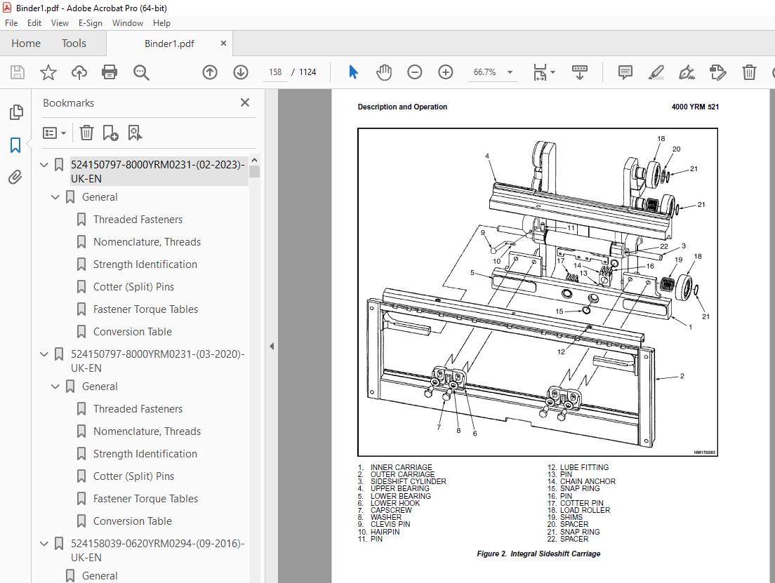
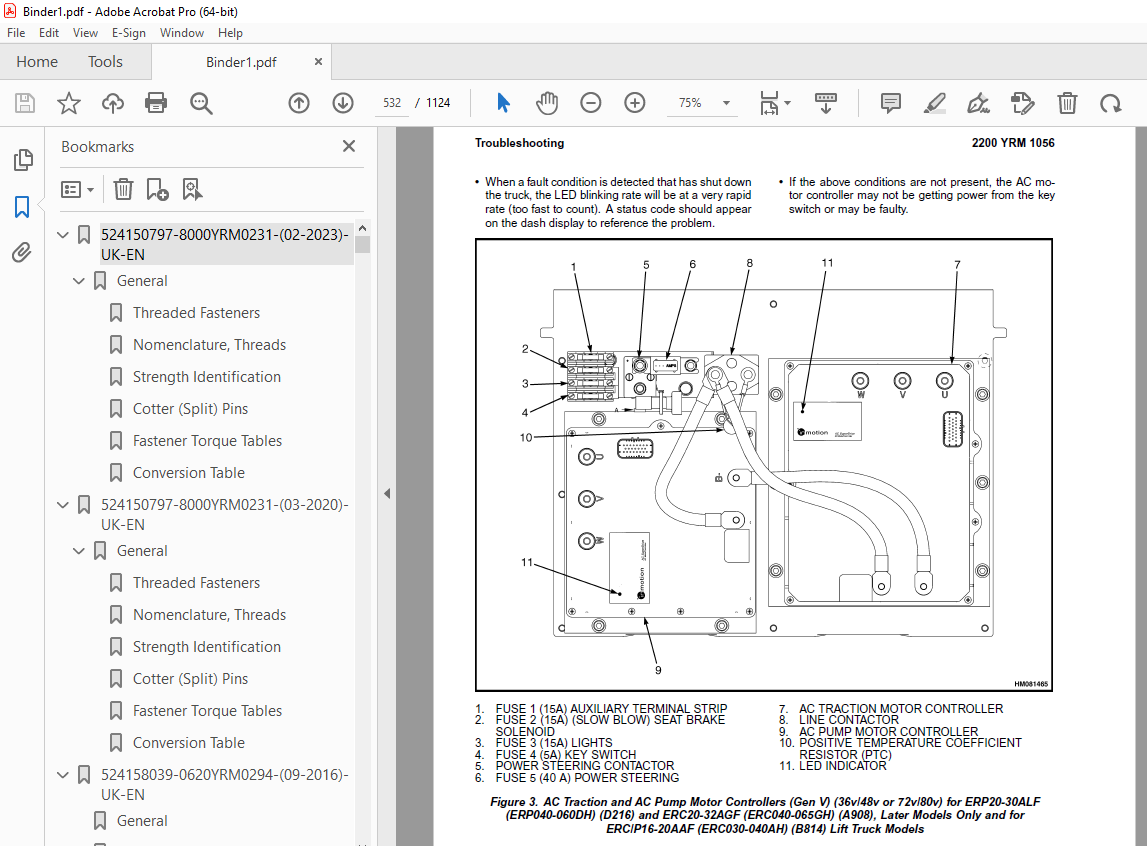
TABLE OF CONTENTS:
Yale Forklift A908 (ERC040-65GH) Service Manual – PDF DOWNLOAD
524150797-8000YRM0231-(02-2023)-UK-EN 1
General 7
Threaded Fasteners 7
Nomenclature, Threads 7
Strength Identification 8
Cotter (Split) Pins 9
Fastener Torque Tables 14
Conversion Table 16
524150797-8000YRM0231-(03-2020)-UK-EN 23
General 27
Threaded Fasteners 27
Nomenclature, Threads 27
Strength Identification 28
Cotter (Split) Pins 29
Fastener Torque Tables 34
Conversion Table 36
524158039-0620YRM0294-(09-2016)-UK-EN 43
General 47
Brush and Commutator Inspection 48
Hydraulic Pump Motor and Traction Motor 48
Steering Pump Motor 51
Normal Commutator Surface 51
Commutator Problems 51
Brush Replacement 56
Stoning the Commutator 59
Motors Repair 60
Disassemble 61
Traction Motor and Hydraulic Pump Motor 61
Steering Pump Motor 62
Assemble 66
Traction Motor and Hydraulic Pump Motor 66
Steering Pump Motor 68
Brush Alignment, Traction and Hydraulic Motors 70
Tests for Damaged Field and Armature 71
Test for an Open Circuit in One Armature Winding 71
Test for Short Circuit in One Armature Winding 71
Test for Short Circuit to Armature Shaft 72
Test for Open Circuit in Field Coil 72
Test for Short Circuit in Field Coil 73
Test for Short Circuit Between Field and Motor Case 73
Brush Holder Test 73
Troubleshooting 74
524158040-2240YRM0001-(01-2023)-UK-EN 79
General 85
Battery Type 85
Lead-Acid Batteries 85
Lithium-Ion Batteries 86
Specific Gravity 86
Chemical Reaction in a Cell 86
Electrical Terms 88
Battery Selection 89
Battery Voltage 90
Battery as a Counterweight 90
Battery Ratings 90
Kilowatt-Hours 90
Battery Maintenance 91
Safety Procedures 91
Maintenance Records 91
New Battery 91
Cleaning Battery 92
Adding Water to Battery 94
Hydrometer 94
Battery Temperature 95
Charging Battery 96
Types of Battery Charges 97
Methods of Charging 98
Troubleshooting Charger 99
Knowing When Battery Is Fully Charged 99
Where to Charge Batteries 99
Equipment Needed 99
Battery Connectors 100
Battery Care 100
Troubleshooting 102
524158040-2240YRM0001-(03-2020)-UK-EN 107
General 111
Battery Type 111
Lead-Acid Batteries 111
Lithium-Ion Batteries 112
Specific Gravity 112
Chemical Reaction in a Cell 112
Electrical Terms 114
Battery Selection 114
Battery Voltage 115
Battery as a Counterweight 116
Battery Ratings 116
Kilowatt-Hours 116
Battery Maintenance 116
Safety Procedures 116
Maintenance Records 117
New Battery 117
Cleaning Battery 117
Adding Water to Battery 119
Hydrometer 120
Battery Temperature 121
Charging Battery 122
Types of Battery Charges 122
Methods of Charging 124
Troubleshooting Charger 124
Knowing When Battery Is Fully Charged 125
Where to Charge Batteries 125
Equipment Needed 125
Battery Connectors 126
Battery Care 126
Troubleshooting 128
524158753-1600YRM0720-(11-2006)-UK-EN 133
toc 133
Steering Housing and Control Unit 133
Safety Precautions Maintenance and Repair 134
General 137
Description 137
Operation 138
Steering Wheel and Column Assembly Repair 139
Assembly Components, Remove 139
Steering Control Unit, Disassemble 144
Steering Control Unit, Clean 144
Steering Control Unit, Assemble 144
Assembly Components, Install 146
System Air Removal 148
Troubleshooting 148
524158890-4000YRM0521-(03-2006)-UK-EN 153
toc 153
Mast 153
Safety Precautions Maintenance and Repair 154
General 157
Description and Operation 157
Carriages 157
Mast Mounts 159
Two-Stage Mast, Limited Free-Lift (LFL) 160
Description and Operation 160
Two-Stage Mast, Full Free-Lift (FFL) 162
Description and Operation 162
Three-Stage Mast, Full Free-Lift (FFL) 164
Description and Operation 164
Four-Stage Mast 166
Description and Operation 166
Cylinder Cushion During Lifting Sequence 170
Cylinder Cushion During Lowering Sequence 171
524179934-0100YRM0558-(11-2007)-UK-EN 175
toc 175
Frame 175
Safety Precautions Maintenance and Repair 176
General 179
Description 179
Main Frame 179
Other Frame Weldments 181
Overhead Guard 181
Overhead Guard Replacement 183
Remove 183
Install 183
Battery and Operator Restraint System, Hood and Seat Brake, and 190
Battery Restraint System 190
Hood 191
Hood With E-Hydraulics 192
Seat Brake 193
Operator Restraint System and Seat Assembly 193
Automatic Locking Retractor (ALR) 193
Emergency Locking Retractor (ELR) 194
Counterweight Replacement 195
Remove 195
Install 196
Traction Motor Replacement 197
Remove 197
Install 199
Hydraulic Tank Repair 200
Inspect 200
Clean 201
Steam Method 201
Chemical Solution 201
Additional Preparations for Repair 202
Small Leaks, Repair 202
Large Leaks, Repair 202
Preparations for Usage After Repair 202
Painting Instructions 202
Safety Label Replacement 204
Battery Specifications 206
tables 175
Table 1 Counterweights 195
Table 2 Lift Truck Models ERC20-30AGF (ERC40-065RF/ZF, ERC40-06 206
Table 3 Lift Truck Models ERC20-30AGF (ERC040-065GH) (A908) 207
524179937-1400YRM0285-(06-2010)-UK-EN 211
toc 211
Drive Axle, Speed Reducer, and Differential 211
Safety Precautions Maintenance and Repair 212
General 215
Description 215
Drive Axle, Speed Reducer, and Differential Repair 217
Drive Axle, Remove 217
Drive Axle, Disassemble 218
Speed Reducer and Differential, Disassemble 218
Clean 220
Inspect 220
Assemble 221
Speed Reducer and Differential, Assemble 221
Input Gear Assembly, Install 221
New Pinion Assembly, Install 222
Drive Axle, Assemble 228
Drive Axle Assembly, Install 228
Torque Specifications 229
Troubleshooting 230
tables 211
Table 1 Adjustment of Shims for Pinion Assembly 222
Table 2 Ring and Pinion Tooth Contact Adjustment 226
524179942-1800YRM0574-(04-2008)-UK-EN 233
toc 233
Brake System 233
Safety Precautions Maintenance and Repair 234
General 237
Description and Operation 237
Service Brakes 237
Master Cylinder 238
Parking Brake 239
Service Brakes Repair 239
Remove and Disassemble 239
Clean 243
Inspect 243
Assemble and Install 243
Adjust 246
Parking Brake Repair 248
Remove and Disassemble 248
Assemble and Install 248
Adjust 249
Master Cylinder Repair 253
Remove 253
Disassemble 254
Clean and Inspect 256
Assemble 256
Install 259
Seat Brake Assembly 259
Seat Brake, Adjust – Lift Truck Models ERC20-30AGF (ERC040-065RF 259
Brake Switch, Adjust – Lift Truck Models ERC20-30AGF (ERC040-065 259
Electric Seat Brake, Adjust for Lift Truck Model ERC20-32AGF (ER 260
Electric Seat Brake Adjustment With Handle For Lift truck Models 262
Remove 262
Clean 262
Inspect 262
Install 264
Adjustments 264
Solenoid Adjustment 264
Traction cutoff Switch Adjustment 264
Cable Adjustment 266
Service Brakes Adjustment 268
Brake Pedal Adjustment 268
Master Cylinder Adjustment 268
Brake System Air Removal 268
Parking Brake Not Applied Switch Test 269
Torque Specifications 269
Troubleshooting 269
524179945-1900YRM0559-(04-2009)-UK-EN 275
toc 275
Hydraulic System 275
Safety Precautions Maintenance and Repair 276
General 279
Description 279
Hydraulic System 279
Operation 287
Hydraulic System 287
Hydraulic Gear Pump 293
Steering Pump 293
Hydraulic Tank Repair 301
Tank, Remove [ERC/P16-20AAF (ERC030-040AF, AG/BG) (A814); ERC/P1 301
Tank, Remove [ERP20-30ALF (B216) and ERP20-30ALF (ERP040-060DH) 303
Tank, Remove [ERP20-32ALF (ERP040-065DH) (E216)] 304
Hydraulic Tank [ERC35-55HG (ERC70-120HH) (B839/C839)] 304
Inspect 305
Small Leaks, Repair 306
Large Leaks, Repair 306
Clean 306
Steam Method 306
Chemical Solution Method 307
Additional Methods for Tank Repair 307
Tank, Install [ERC/P16-20AAF (ERC030-040AF, AG/BG) (A814); ERC/P 307
Tank, Install [ERP20-30ALF (B216) and ERP20-30ALF (ERP040-060DH) 308
Tank, Install [ERP20-32ALF (ERP040-065DH) (E216)] 308
Filter Replacement 309
All Lift Trucks Except [ERC35-55HG (ERC70-120HH) (B839/C839); ER 309
Remove 309
Install 310
Lift Truck Models [ERC35-55HG (ERC70-120HH) (B839/C839)] 310
Remove 310
Install 310
Lift truck Models [ERC20-32AGF (ERC040-065GH) (A908) and ERC/P16 311
Remove 311
Install 311
Lift Truck Models [ERP20-32ALF (ERP040-065DH) (E216)] 313
Remove 313
Install 313
Hydraulic Pump Repair 316
Hydraulic Pump, Remove [ERC/P16-20AAF (ERC030-040AF, AG/BG) (A81 316
Hydraulic Pump, Disassemble ERC/P16-20AAF (ERC030-040AF, AG/BG) 316
Inspect 318
Clean 318
Pump Seal Replace and Pump Assemble 318
Assemble Pump on Motor 318
Hydraulic Pump and Motor, Install [ERC/P16-20AAF (ERC030-040AF, 320
Hydraulic Pump, Remove [ERP20-30ALF (B216); ERP20-30ALF (ERP040- 321
Hydraulic Pump, Disassemble [ERC35-55HG (ERC70-120HH) (B839/C839 322
Hydraulic Pump, Inspect [ERC35-55HG (ERC70-120HH) (B839/C839) an 324
Hydraulic Pump, Clean [ERC35-55HG (ERC70-120HH) (B839/C839) and 324
Hydraulic Pump, Assemble [ERC35-55HG (ERC70-120HH) (B839/C839) a 324
Hydraulic Pump and Motor, Install [ERP20-30ALF (B216); ERP20-30A 324
Main Control Valve Repair 326
Steering Pump Repair 326
Pump, Remove and Disassemble [ERC/P16-20AAF (ERC030-040AF, ERC03 326
Pump, Remove and Disassemble [ERP20-30ALF (B216); ERP20-30ALF (E 328
Pump, Assemble and Install 330
Steering Control Unit Replacement 331
Remove 331
Install 331
Steering Cylinder Repair 337
Main Control Valve Check and Adjust 337
Steering Relief Valve Check and Adjust 338
Specifications 338
Relief Valve Pressures* 338
Hydraulic Tank Capacity (dipstick full mark) 339
Hydraulic Pump Capacities – All Models Except ERC35-55HG (ERC70- 339
Hydraulic Pump Capacities – Models ERC35-55HG (ERC70-120HH) (B83 339
Troubleshooting 339
Steering 339
Steering Housing and Steering Control Unit 340
Hydraulic System 341
524179946-2000YRM0562-(02-2009)-UK-EN 347
toc 347
Manual hydraulic Control Valve 347
Safety Precautions Maintenance and Repair 348
General 351
Description 351
Operation 354
ERC/P16-20AAF (ERC030-040AF, AG/BG) (A814); ERC/P16-20AAF (ERC03 354
ERP20-30ALF (B216), ERP20-30ALF (ERP040-060DH) (D216) and ERP20- 354
Lift Section 356
Tilt Section 356
Tilt Backward 356
Tilt Forward 356
Relief Valve 358
Main Control Valve Repair 359
Main Control Valve Without OPS Solenoid 359
Remove 359
Disassemble 359
Clean and Inspect 363
Assemble 363
Install [ERC/P16-20AAF (ERC030-040AF, AG/BG) (A814); ERC/P16-20A 364
Install [ERP20-30ALF (B216), ERP20-30ALF (ERP040-060DH) (D216) a 364
Main Control Valve With OPS Solenoid 365
Remove 365
Disassemble 365
Clean and Inspect 367
Relief Valve Repair 369
Assemble 370
Install 371
Control Lever Linkage Repair 371
Remove [ERC/P16-20AAF (ERC030-040AF, AG/BG) (A814),ERC/P16-20AAF 371
Disassemble [ERC/P16-20AAF (ERC030-040AF, AG/BG) (A814),ERC/P16- 371
Assemble and Install [ERC/P16-20AAF (ERC030-040AF, AG/BG) (A814) 373
Control Valve Linkage Repair 373
Remove and Disassemble [ERC/P16-20AAF (ERC030-040AF, AG/BG) (A81 373
Assemble and Install [ERC/P16-20AAF (ERC030-040AF, AG/BG) (A814) 374
Control Lever Linkage Repair 374
Remove [ERP20-30ALF (B216), ERP20-30ALF (ERP040-060DH) (D216) an 374
Disassemble [ERP20-30ALF (B216), ERP20-30ALF (ERP040-060DH) (D21 376
Assemble and Install [ERP20-30ALF (B216), ERP20-30ALF (ERP040-06 376
Pressure Relief Valve Check and Adjustment 377
Primary Relief Valve 377
Secondary Relief Valve 378
Troubleshooting 379
524179953-4000YRM0563-(04-2005)-UK-EN 383
toc 383
Four-Stage Mast 383
Safety Precautions Maintenance and Repair 384
General 387
Description 387
Carriages 387
Mast Mounts 388
Mast 388
Description 388
Operation 389
Forks Repair 392
Remove 392
Install 392
Safety Procedures When Working Near Mast 394
Carriage Repair 396
Remove 396
Standard Carriage 396
Sideshift Carriage 397
Repairs 398
Install 398
Standard Carriage 398
Sideshift Carriage 398
Mast Repair 399
Remove 399
Disassemble 399
Clean and Inspect 400
Assemble 401
Install 403
Lift Cylinders Repair 406
Remove 406
Main Lift Cylinders 406
Free-Lift Cylinders 406
Disassemble 406
Assemble 408
Install 410
Main Lift Cylinder 410
Free-Lift Cylinder 411
Header Hose Arrangements 412
Header Hoses, Install 412
Lift and Tilt System Leaks Check 419
Lift Cylinders Leaks Check 419
Tilt Cylinders Leaks Check 419
Tilt Cylinders Adjustment 420
Lift Chain Adjustments 421
Mast Adjustments 422
Carriage Adjustments 424
Troubleshooting 425
tables 383
Table 1 Standard Four-Stage Hose Dimensions 418
Table 2 Hook type Carriage Chain Adjustment 421
Table 3 Pin-Type Carriage Chain Adjustment 422
524183081-1600YRM1054-(11-2006)-UK-EN 429
toc 429
Steering System for AC Electric Lift Trucks 429
Safety Precautions Maintenance and Repair 430
General 433
Description 434
Steering Wheel and Column Assembly Repair 435
General 435
Assembly Components, Remove 437
Assembly Components, Install 438
Power Steering Motor and Pump 439
Description 439
Remove 439
Disassemble 442
Install 442
Power Steering Pump, Repair 442
Seal, Replace 443
Steering System Air Removal 444
Steering Pressure Check 444
Steering Motor Circuits Check 445
Troubleshooting 446
524183082-2200YRM1055-(10-2009)-UK-EN 451
toc 451
Electrical System (Trucks With AC Controllers) 451
Safety Precautions Maintenance and Repair 452
General 455
Description 456
Features of the Display Panels 456
Other Control Components 457
Display Panel and Key Switch Replacement 458
Display Panel, Replace 458
Key Switch, Replace 460
Controller Replacement 460
Traction and Pump Motor Controller Replacement 460
Master Controller, Replace 466
Master Controller, Remove ERP20-30ALF (ERP040-060DH) (D216), ERP 466
Master Controller, Install ERP20-30ALF (ERP040-060DH) (D216), ER 466
Master Controller, Remove ERC/P16-20AAF (ERC030-040AH) (B814/C81 468
Master Controller, Install ERC/P16-20AAF (ERC030-040AH) (B814/C8 468
Master Controller, Remove ERC35-55HG (ERC070-120HH) (B839/C839) 470
Master Controller, Install ERC35-55HG (ERC070-120HH) (B839/C839) 470
Control Components Replacement 471
General 471
Start Switch, Replace 471
Brake Light Switch, Replace 472
Seat Switch, Replace 472
Parking Brake Switch, Replace 473
Foot Directional Control Pedal Direction Switches, Replace 475
Steering Column Direction Control Switches, Replace 478
Remove 478
Install 478
Brake Fluid Switch, Replace 480
Brush Wear and Over Temperature Sensors (DC Pump Motor Only) 480
Rocker Switches for Lights, Replace 480
Accelerator Position Sensor, Replace 481
On-Demand Steering Sensor, Replace 482
Lights, Converter, Relay, and Reverse Alarm 482
Brake, Tail, and Reverse Light Assembly, Replace 483
Incandescent Assembly 483
LED Assembly – Remove 485
LED Assembly – Install 485
Strobe Light Assembly, Replace 488
Wire Harness Repair 489
Del-City Crimp-Solder-Shrink Splice 489
Front, Rear Driving Light or Spot Light Assemblies, Replace 490
Converter, Replace 490
Remove, Lift Truck Models ERP20-30ALF (ERP040-060DH) (D216), ERP 490
Install, Lift Truck Models ERP20-30ALF (ERP040-060DH) (D216), ER 492
Remove, Lift Truck Models ERC20-32AGF (ERC040-065GH) (A908) and 492
Install, Lift Truck Models ERC20-32AGF (ERC040-065GH) (A908) and 492
Remove, Lift Truck Models ERC35-55HG (ERC70-120HH) (B839/C839) 494
Install, Lift Truck Models ERC35-55HG (ERC70-120HH) (B839/C839) 494
Reverse Relay, Replace 495
Lift Truck Models ERC20-32AGF (ERC040-065GH) (A908), ERC/P16-20A 495
Lift Truck Models ERC35-55HG (ERC70-120HH) (B839/C839) 495
Backup Alarm, Replace 497
Horn and Horn Button, Replace 497
Horn Replacement for Lift Trucks ERP20-30ALF (ERP040-060DH) (D21 497
Horn Replacement for Lift Trucks ERC35-55HG (ERC70-120HH) (B839/ 499
Horn Switch and Cover, Replace 500
Hydraulic Pump Switches 501
Fan Power Supply, Replace 501
Remove, Lift Truck Models ERC35-55HG (ERC70-120HH) (B839/C839) 501
Install, Lift Truck Models ERC35-55HG (ERC70-120HH) (B839/C839) 501
Remove, Lift Truck Models ERP20-30ALF (ERP040-060DH) (D216) and 502
Install, Lift Truck Models ERP20-30ALF (ERP040-060DH) (D216) and 503
Remove, Lift Truck Models ERC20-32AGF (ERC040-065GH) (A908) 503
Install, Lift Truck Models ERC20-32AGF (ERC040-065GH) (A908) 503
Control and Power Fuse Check 504
Fuse Locations 504
Brake Light Switch Adjustment 510
Seat Switch Check 511
Seat Brake Adjustment 511
Parking Brake Switch Adjustment 512
Direction Switches Check 512
Foot Directional Control Pedal 512
Steering Column 513
Foot Directional Control Pedal or Accelerator Pedal Adjustment 513
Accelerator Position Sensor Adjustment and Start Switch Adjustme 514
Acceleration Position Sensor, Adjust 514
Start Switch, Adjust 516
tables 451
Table 1 Wire Splice Size 489
524183083-2200YRM1056-(03-2009)-UK-EN 519
toc 519
AC Motor Controllers/Display Panel 519
Safety Precautions Maintenance and Repair 520
Description 523
General 523
AC Motors 523
Motor Controllers 523
Master Controller 523
Dash Display 523
Controller Area Network Bus (CANbus) 523
Master Controller Checks and Adjustments 524
Function Settings 525
General 525
Function Numbers 525
Function Descriptions 528
General 528
Function Number 1 BATTERY VOLTAGE 528
Function Number 2 EXTENDED SHIFT 528
Function Number 3 ACCELERATION 1 528
Function Number 4 ACCELERATION 2 528
Function Number 5 TOP SPEED LIMIT 528
Function Number 6 REGEN BRAKING 528
Function Number 7 AUTO DECELERATION 529
Function Number 8 BDI ADJUSTMENT 529
Function Number 9 LIFT INTERRUPT 529
Function Number 10 POWER STEERING TIME DELAY 529
Function Number 11 SERVICE REMINDER 529
Function Number 12 CUSTOM 529
Function Number 13 PUMP SPEED 1 529
Function Number 14 PUMP SPEED 2 530
Function Number 15 PUMP SPEED 3 530
Function Number 16 PUMP ACCELERATION 530
Troubleshooting 530
General 530
Controller Status Light Emitting Diodes (LEDs) 531
Master Controller 531
AC Motor Controllers 531
Status Codes 537
AC Motor Controllers Status Code Charts 539
Troubleshooting When Dash and/or Lift Truck is not Operational 560
Typical Symptoms 560
Truck Runs but Dash Display is not Operational, or Only Displays 560
Truck Does Not Run and Dash is Not Operational or Only Displays 561
Hydraulics Operate Normally, Traction Does Not Operate Correctly 562
Traction Operates Normally, Hydraulics do Not Operate Correctly, 562
AC Transistor Motor Controller Replacement 562
General 562
General Maintenance Instructions 568
Special Precautions 568
Fuses 569
Fan Test 569
Contactors 569
Repair 569
Thermal Sensors 573
Motor Controller, Replace 573
Display Panel 574
General 574
Premium Display Panel 574
Standard Display Panel 574
Display Functions and Features 575
Key-On Initialization 575
Standard Display 576
Premium Display 576
Lift Truck Inspection Function 577
Access to Service Functions 577
Service Functions 577
Service Functions 578
Performance Modes 580
Battery Discharge Indicator (BDI) 580
Hourmeter 581
Dash Display Service Menu Navigation 587
General 587
Moving Through Menu Selections 587
Editing and Adding Information 587
tables 519
Table 1 Factory Parameters for ERP20-30ALF (ERP040-060DH) (D216 525
Table 2 Factory Setting for ERC020-032AGF (ERC40-65GH) (A908) 526
Table 3 Factory Setting for ERC/P16-20AAF (ERC030-040AH) (B814/ 526
Table 4 Factory Parameters for ERC35-55HG (ERC70-120HH) (B839/C 527
Table 5 List of Status Codes 537
Table 6 42-Pin Connections/Descriptions for Master Controller 570
Table 7 Pin Connections/Descriptions for 72/80 (Gen IV) Volt Mo 572
Table 8 Pin Connections/Descriptions for 36/48 and 72v/80v (Gen 572
524183085-2200YRM1058-(04-2011)-UK-EN 591
toc 591
Troubleshooting and Adjustments Using the AC Controls Program (E 591
Safety Precautions Maintenance and Repair 592
General 595
Computer Requirements 595
Software, Install 595
Language Selection 595
Demo Mode 596
Connect PC to Lift Truck 600
Starting AC Controls Program 602
Lift Truck Control Setup 607
Change Lift Truck Serial Number or Hourmeter 607
Setting Factory Default Values or Changing Lift Truck Parameters 608
Create New Custom Lift Truck Configuration 614
Lift Truck Configuration Properties 617
Import New Lift Truck Configuration From Disk 620
Delete Custom Lift Truck Configuration or Password File 622
Dash Display 625
Custom Display Languages 625
Download Display Language 627
Clear Operator Log 627
Password Functions 630
Enable/Disable Password and Lift Truck Inspection Functions 630
Truck Inspection Checklist 630
Password 630
Password Properties 630
Create New Password File 635
Download Passwords 636
Upload Passwords 638
Reports Menu 640
Devices Report 640
Custom Report 640
Password Report 640
Operator Report 647
Current Settings Report 650
Status Code Report 654
Status Codes Log 657
Troubleshooting 659
Diagnostics 659
Help Menu 662
General 662
Contents 662
Technical Support 662
About Electric Truck AC Controls Program 662
524183086-8000YRM1059-(08-2012)-UK-EN 669
toc 669
Electrical Diagrams 669
Safety Precautions Maintenance and Repair 670
524183087-8000YRM1060-(02-2010)-UK-EN 745
toc 745
Periodic Maintenance 745
Safety Precautions Maintenance and Repair 746
General 751
Serial Number Data 751
How to Move Disabled Lift Truck 751
How to Tow Lift Truck 751
How to Put Lift Truck on Blocks 752
How to Raise Drive Tires 752
How to Raise Steering Tires 752
How to Clean a Lift Truck 752
Maintenance Schedule 754
Maintenance Procedures Every 8 Hours or Daily 761
How to Make Checks With Key OFF 761
Tires and Wheels 761
Forks 762
Inspect 762
Mast and Lift Chains, Inspect 763
Safety Labels 763
Steering Column Latch 763
Operator Restraint System 764
Automatic Locking Retractor (ALR) 764
Emergency Locking Retractor (ELR) 764
Battery Restraint System ERC20-32AGF (ERC040-065GH) (A908) and E 765
Battery Restraint System ERP20-30ALF (ERP040-060DH) (D216) Lift 766
Battery 766
Attachment 767
Hydraulic System 767
How to Make Checks With Key ON 768
Horn, Lights, and Alarm 768
Steering System 768
Service Brakes 768
Parking Brake 768
Control Levers and Pedals 769
Direction and Speed Control Pedals 769
Lift System Operation 769
Oil Leaks 769
First Service After First 100 Hours of Operation 769
Change Filter for Hydraulic Oil 769
Maintenance Procedures Every 250 Hours or 6 Weeks 771
Steering King Pins ERC/P16-20AAF (B814/C814) Trucks Only 771
Steering Tie Rods and Spindles 771
Maintenance Procedures Every 500 Hours or 3 Months 771
Differential and Speed Reducer ERC20-32AGF (ERC040-065GH) (A908) 771
Wheel Nut Torques 772
Header Hose Checks 772
Mast Lubrication 772
Forks 776
Remove 776
Inspect 776
Install 776
Adjust 777
Brake Fluid ERC/P16-20AAF (ERC030-040AH) (B814/C814) and ERC20-3 777
Parking Brake Adjustment 777
Seat Brake Operations Check 778
Maintenance Procedures Every 1000 Hours or 6 Months 778
Lift Chains 778
Wear Check 778
Lift Chain Lubrication 779
Forks 779
Check Upper and Lower Bearings, Integral Sideshift Carriage 779
Steering King Pins ERC20-32AGF (ERC040-065GH) (A908) Lift Truck 780
Steering Tie Rods ERP20-30ALF (ERP040-060DH) (D216) Lift Truck M 780
Steering Axle Spindles 780
King Pins ERP20-30ALF (ERP040-060DH) (D216) 780
Hydraulic Tank Breather 780
ERP20-30ALF (ERP040-060DH) (D216) 780
ERC20-32AGF (ERC040-065GH) (A908) 781
ERC/P16-20AAF (ERC030-040AH) (B814/C814) 781
Differential and Speed Reducer ERP20-30ALF (ERP040-060DH) (D216) 781
Brake Fluid ERP20-30ALF (ERP040-060DH) (D216) Lift Truck Models 782
Other Lubrication 782
Electrical Inspection 782
Contactors 782
Motor Brushes (DC Pump) 782
Motor Brushes, General 782
Maintenance Procedures Every 2000 Hours or Yearly 786
Hydraulic System 786
Change Filter for Hydraulic Oil 786
Change Hydraulic Oil 787
Differential and Speed Reducer 787
Brake Fluid Replacement 788
Service Brakes 788
Steering Tie Rods and Spindle Lift Truck Models ERC030-040AH (B8 788
Wheel Bearings 789
Steer Wheels, Lubrication 789
Drive Wheels, Lubrication 789
Lift Chains 789
Forks 789
Replace Upper and Lower Bearings, Integral Sideshift Carriage 789
Other Lubrication 789
Battery Maintenance 790
How to Charge Battery 790
How to Change Battery for ERP20-30ALF (ERP040-060DH) (D216) and 791
General 791
How to Change Battery for ERC20-32AGF (ERC040-065GH) (A908) and 793
General 793
Lift and Tilt System Leak Check 796
Lift Cylinders Leak Check 796
Tilt Cylinders Leak Check 797
Safety Procedures When Working Near Mast 797
WHEN WORKING NEAR THE MAST ALWAYS: 797
Lift Chain Adjustments 800
Welding Repairs 801
Overhead Guard Changes 801
Wheels and Tire Maintenance 802
Solid Rubber Tires ERC20-32AGF (ERC040-065GH) (A908) and ERC/P16 802
Remove Wheels From Lift Truck 802
Remove and Install Tire on Wheel 802
Pneumatic Tires and Wheels ERP20-30ALF (ERP040-060DH) (D216) 803
Remove Wheels From Lift Truck 803
Remove Wheel From Pneumatic Tire 804
Install Three- or Four-Piece Wheel in Pneumatic Tire 805
Add Air to Tires 806
Wheels, Install 806
Solid Rubber Tires on Pneumatic Wheels 807
Remove Wheels From Lift Truck 807
Remove Solid Rubber Tire From Pneumatic Wheel 807
Install Solid Rubber Tire on Pneumatic Wheel 809
Wheels, Install 810
Snap-On Tire, Change 810
Remove Snap-On Solid Tire From Wheel 811
Install Snap-On Solid Tire on Wheel 812
Adhesives and Sealants 813
tables 745
Table 1 Maintenance Schedule 756
524204007-8000YRM1083-(01-2006)-UK-EN 817
toc 817
Capacities and Specifications 817
Safety Precautions Maintenance and Repair 818
Counterweights 821
Hydraulic System 821
Steering System 822
Specifications 822
Turning Radius 822
Wheels and Tires 823
Battery Specifications 824
ERC20-30AGF (ERC050-065GH) 824
Capacities 825
Drift Rates (Maximum) for Tilt Cylinders 825
Mast Speeds 826
ERC20-30AGF (ERC040-065GH) Mast Speeds (36 or 48 Volt) Americas 826
ERC20-30AGF Mast Speeds (72 or 80 Volt) Europe 828
ERC20-30AGF Mast Speeds (72 or 80 Volt) Europe 829
Torque Specifications 830
Frame 830
Drive Axle, Speed Reducer, and Differential ERC20-30AGF 830
Steering Axle ERC20-30AGF 831
Masts 831
Seat Brake 831
Hydraulic Pump and Fittings 831
Adhesives and Sealants 832
tables 817
Table 1 Manual Hydraulic Control Valve 821
Table 2 E-Hydraulic Control Valve 821
524205680-0620YRM1098-(03-2010)-UK-EN 835
toc 835
AC Motor Repair 835
Safety Precautions Maintenance and Repair 836
General 839
AC Motor Repair 839
Disassemble 839
Assemble 843
Troubleshooting 845
524223768-2100YRM1139-(02-2014)-UK-EN 849
524223776-4000YRM1148-(09-2015)-UK-EN 897
General 901
Safety Procedures When Working Near Mast 902
Fork Replacement 904
Remove, Lift Trucks Not Equipped With Fork Positioner Or Equipped With Fork Positioner Before August, 2012 904
Remove, Lift Trucks Manufactured After August, 2012 And Equipped With Fork Positioner 906
Install, Lift Trucks Not Equipped With Fork Positioner Or Equipped With Fork Positioner Before August, 2012 907
Install, Lift Trucks Manufactured After August, 2012 And Equipped With Fork Positioner 907
Checks, Lift Trucks Not Equipped With Fork Positioner Or Equipped With Fork Positioner Before August, 2012 908
Checks, Lift Trucks Manufactured After August, 2012 And Equipped With Fork Positioner 909
Carriages Repair 910
Standard Carriage 910
Remove 910
Repair 911
Install 911
Standard Carriage, Remove 912
Hang-On Sideshift Carriage, Remove 913
Standard Carriage and Hang-On Sideshift Carriage, Repair 914
Standard Carriage, Install 915
Hang-On Sideshift Carriage, Install 915
Integral Sideshift Carriage 916
Remove 916
Clean and Inspect 919
Repair 920
Install 920
Fork Positioner 921
Remove 921
Clean and Inspect 926
Disassemble and Assemble 926
Install 926
Fork Positioner Hydraulic Hose Adjustment 927
Disconnecting Attachment Hydraulic Quick Disconnect Hoses 929
Connecting Attachment Hydraulic Quick Disconnect Hoses 929
Mast Repair 930
Mast, Remove 930
Two-Stage LFL and Two-Stage FFL Masts 933
Disassemble 933
Clean and Inspect 943
Three-Stage FFL Mast 944
Disassemble 944
Clean and Inspect 952
Two-Stage LFL and Two-Stage FFL Mast 954
Assemble 954
Three-Stage FFL Mast 957
Assemble 957
Four-Stage FFL Mast – Manufactured Before July, 2009 959
Disassemble 959
Clean and Inspect 964
Assemble 966
Four-Stage FFL Mast – Manufactured After July, 2009 967
Disassemble 967
Clean and Inspect 974
Assemble 977
Mast, Install 978
Header Hose Arrangement 981
Two-Stage LFL 981
Two-Stage FFL 989
Three-Stage FFL 1004
Standard 1004
Optional Equipment Lift Truck GLP/GDP20-35VX (GP/GLP/GDP040-070VX) (B875) 1021
Four-Stage FFL Mast – Manufactured Before July, 2009 1029
Four-Stage FFL Mast – Manufactured After July, 2009 1038
Adjustment 1045
Lift Chains Adjustment 1045
Carriage Adjustments 1048
Mast Adjustments 1048
Load Roller Adjustment 1048
Mast Side Kicking Adjustment 1051
524256687-2000YRM1224-(04-2008)-UK-EN 1055
toc 1055
Electro-hydraulic Control Valve 1055
Safety Precautions Maintenance and Repair 1056
General 1059
Description 1059
Electro-Hydraulic Control System 1059
Electro-Hydraulic Control Valve 1062
Electro-Hydraulic Valve Driver Module 1078
Mini-Lever Module (MLM) 1078
Joystick 1079
Electro-Hydraulic Control Valve Repair 1080
Remove 1080
Disassemble 1089
Solenoid Coil Replacement 1091
Cartridge Replacement 1093
Electro-Hydraulic Pressure Reducing Valve (EHPR) Replacement 1094
Lift Circuit Check Valve Replacement 1095
Compensator Cartridge Replacement 1095
Primary and Secondary Relief Valves Replacement 1095
Tilt Counterbalance Valve Replacement 1096
Flow Regulator Valve Replacement 1096
Assemble 1096
Install 1096
E-Hydraulics Calibration 1105
Mini-Lever Module 1107
Mini-Lever Module (MLM) 1107
Remove 1107
Install 1107
Mini-Lever Replacement 1107
Remove 1107
Clean and Inspect 1108
Install 1108
Push Button Switch Replacement 1109
Remove 1109
Install 1110
Test 1111
Mini-levers 1111
Full Stroke Test 1111
Function Returns to Neutral Test 1111
Push Button Switch 1112
Joystick 1112
Remove and Disassemble 1112
Inspect 1112
Assemble and Install 1112
Troubleshooting 1113
tables 1055
Table 1 Primary and Secondary Relief Valve Values 1065
Table 2 Solenoid Resistance Values 1091
Table 3 Cartridge and Solenoid Coil Nut Torque for Lift truck M 1094
Table 4 Cartridge and Solenoid Coil Nut Torque for Lift truck M 1094
More products