$41.95
Yale Forklift A908 (ERC20-32AGF) Service Manual - PDF
Yale Forklift A908 (ERC20-32AGF) Service Manual – PDF DOWNLOAD
FILE DETAILS:
Yale Forklift A908 (ERC20-32AGF) Service Manual – PDF DOWNLOAD
Language : English
Pages : 1832
Downloadable : Yes
File Type : PDF
PART NO. 524150797
IMAGES PREVIEW OF THE MANUAL:
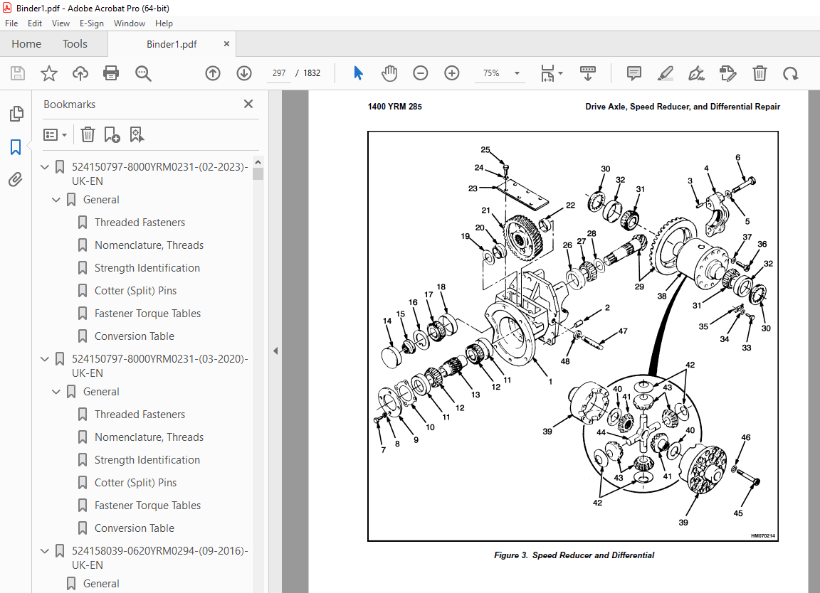
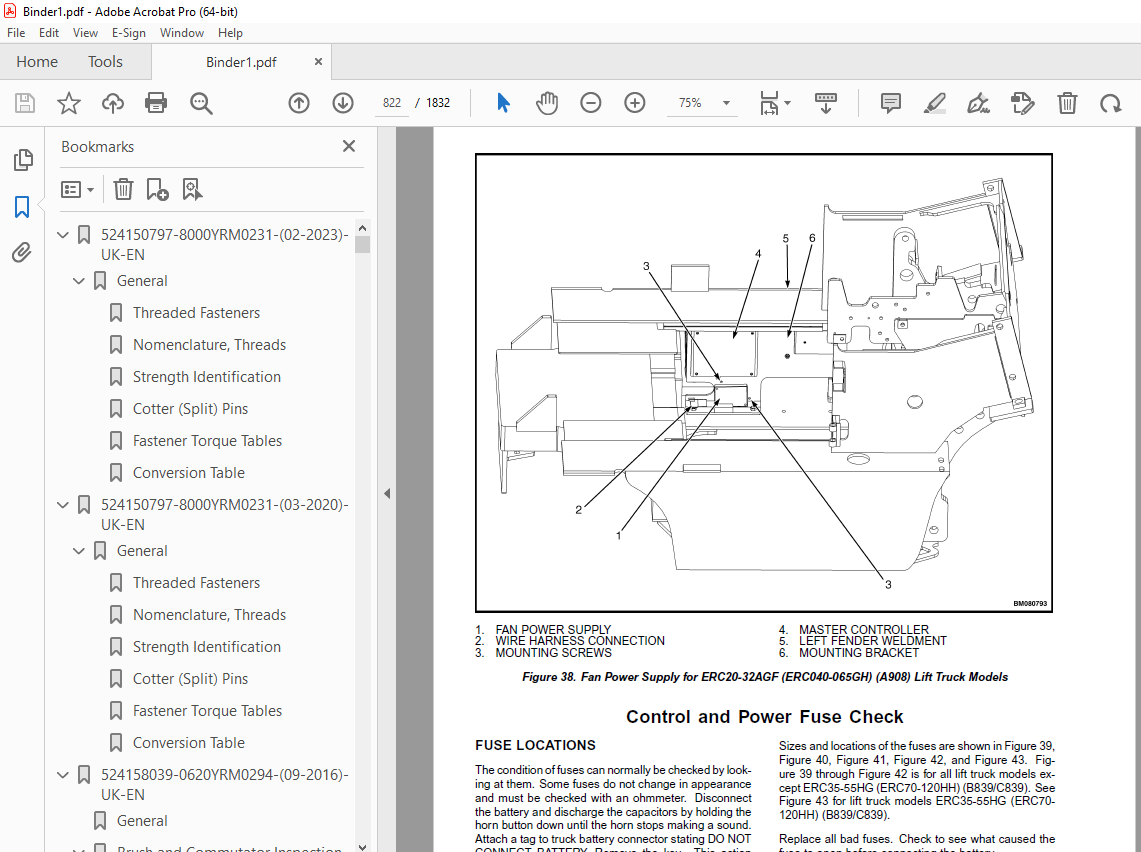
TABLE OF CONTENTS:
Yale Forklift A908 (ERC20-32AGF) Service Manual – PDF DOWNLOAD
524150797-8000YRM0231-(02-2023)-UK-EN 1
General 7
Threaded Fasteners 7
Nomenclature, Threads 7
Strength Identification 8
Cotter (Split) Pins 9
Fastener Torque Tables 14
Conversion Table 16
524150797-8000YRM0231-(03-2020)-UK-EN 23
General 27
Threaded Fasteners 27
Nomenclature, Threads 27
Strength Identification 28
Cotter (Split) Pins 29
Fastener Torque Tables 34
Conversion Table 36
524158039-0620YRM0294-(09-2016)-UK-EN 43
General 47
Brush and Commutator Inspection 48
Hydraulic Pump Motor and Traction Motor 48
Steering Pump Motor 51
Normal Commutator Surface 51
Commutator Problems 51
Brush Replacement 56
Stoning the Commutator 59
Motors Repair 60
Disassemble 61
Traction Motor and Hydraulic Pump Motor 61
Steering Pump Motor 62
Assemble 66
Traction Motor and Hydraulic Pump Motor 66
Steering Pump Motor 68
Brush Alignment, Traction and Hydraulic Motors 70
Tests for Damaged Field and Armature 71
Test for an Open Circuit in One Armature Winding 71
Test for Short Circuit in One Armature Winding 71
Test for Short Circuit to Armature Shaft 72
Test for Open Circuit in Field Coil 72
Test for Short Circuit in Field Coil 73
Test for Short Circuit Between Field and Motor Case 73
Brush Holder Test 73
Troubleshooting 74
524158040-2240YRM0001-(01-2023)-UK-EN 79
General 85
Battery Type 85
Lead-Acid Batteries 85
Lithium-Ion Batteries 86
Specific Gravity 86
Chemical Reaction in a Cell 86
Electrical Terms 88
Battery Selection 89
Battery Voltage 90
Battery as a Counterweight 90
Battery Ratings 90
Kilowatt-Hours 90
Battery Maintenance 91
Safety Procedures 91
Maintenance Records 91
New Battery 91
Cleaning Battery 92
Adding Water to Battery 94
Hydrometer 94
Battery Temperature 95
Charging Battery 96
Types of Battery Charges 97
Methods of Charging 98
Troubleshooting Charger 99
Knowing When Battery Is Fully Charged 99
Where to Charge Batteries 99
Equipment Needed 99
Battery Connectors 100
Battery Care 100
Troubleshooting 102
524158040-2240YRM0001-(03-2020)-UK-EN 107
General 111
Battery Type 111
Lead-Acid Batteries 111
Lithium-Ion Batteries 112
Specific Gravity 112
Chemical Reaction in a Cell 112
Electrical Terms 114
Battery Selection 114
Battery Voltage 115
Battery as a Counterweight 116
Battery Ratings 116
Kilowatt-Hours 116
Battery Maintenance 116
Safety Procedures 116
Maintenance Records 117
New Battery 117
Cleaning Battery 117
Adding Water to Battery 119
Hydrometer 120
Battery Temperature 121
Charging Battery 122
Types of Battery Charges 122
Methods of Charging 124
Troubleshooting Charger 124
Knowing When Battery Is Fully Charged 125
Where to Charge Batteries 125
Equipment Needed 125
Battery Connectors 126
Battery Care 126
Troubleshooting 128
524158753-1600YRM0720-(11-2006)-UK-EN (2) 133
toc 133
Steering Housing and Control Unit 133
Safety Precautions Maintenance and Repair 134
General 137
Description 137
Operation 138
Steering Wheel and Column Assembly Repair 139
Assembly Components, Remove 139
Steering Control Unit, Disassemble 144
Steering Control Unit, Clean 144
Steering Control Unit, Assemble 144
Assembly Components, Install 146
System Air Removal 148
Troubleshooting 148
524158753-1600YRM0720-(11-2006)-UK-EN 153
toc 153
Steering Housing and Control Unit 153
Safety Precautions Maintenance and Repair 154
General 157
Description 157
Operation 158
Steering Wheel and Column Assembly Repair 159
Assembly Components, Remove 159
Steering Control Unit, Disassemble 164
Steering Control Unit, Clean 164
Steering Control Unit, Assemble 164
Assembly Components, Install 166
System Air Removal 168
Troubleshooting 168
524158890-4000YRM0521-(03-2006)-UK-EN (2) 173
toc 173
Mast 173
Safety Precautions Maintenance and Repair 174
General 177
Description and Operation 177
Carriages 177
Mast Mounts 179
Two-Stage Mast, Limited Free-Lift (LFL) 180
Description and Operation 180
Two-Stage Mast, Full Free-Lift (FFL) 182
Description and Operation 182
Three-Stage Mast, Full Free-Lift (FFL) 184
Description and Operation 184
Four-Stage Mast 186
Description and Operation 186
Cylinder Cushion During Lifting Sequence 190
Cylinder Cushion During Lowering Sequence 191
524158890-4000YRM0521-(03-2006)-UK-EN 195
toc 195
Mast 195
Safety Precautions Maintenance and Repair 196
General 199
Description and Operation 199
Carriages 199
Mast Mounts 201
Two-Stage Mast, Limited Free-Lift (LFL) 202
Description and Operation 202
Two-Stage Mast, Full Free-Lift (FFL) 204
Description and Operation 204
Three-Stage Mast, Full Free-Lift (FFL) 206
Description and Operation 206
Four-Stage Mast 208
Description and Operation 208
Cylinder Cushion During Lifting Sequence 212
Cylinder Cushion During Lowering Sequence 213
524179934-0100YRM0558-(11-2007)-UK-EN (2) 217
toc 217
Frame 217
Safety Precautions Maintenance and Repair 218
General 221
Description 221
Main Frame 221
Other Frame Weldments 223
Overhead Guard 223
Overhead Guard Replacement 225
Remove 225
Install 225
Battery and Operator Restraint System, Hood and Seat Brake, and 232
Battery Restraint System 232
Hood 233
Hood With E-Hydraulics 234
Seat Brake 235
Operator Restraint System and Seat Assembly 235
Automatic Locking Retractor (ALR) 235
Emergency Locking Retractor (ELR) 236
Counterweight Replacement 237
Remove 237
Install 238
Traction Motor Replacement 239
Remove 239
Install 241
Hydraulic Tank Repair 242
Inspect 242
Clean 243
Steam Method 243
Chemical Solution 243
Additional Preparations for Repair 244
Small Leaks, Repair 244
Large Leaks, Repair 244
Preparations for Usage After Repair 244
Painting Instructions 244
Safety Label Replacement 246
Battery Specifications 248
tables 217
Table 1 Counterweights 237
Table 2 Lift Truck Models ERC20-30AGF (ERC40-065RF/ZF, ERC40-06 248
Table 3 Lift Truck Models ERC20-30AGF (ERC040-065GH) (A908) 249
524179934-0100YRM0558-(11-2007)-UK-EN 253
toc 253
Frame 253
Safety Precautions Maintenance and Repair 254
General 257
Description 257
Main Frame 257
Other Frame Weldments 259
Overhead Guard 259
Overhead Guard Replacement 261
Remove 261
Install 261
Battery and Operator Restraint System, Hood and Seat Brake, and 268
Battery Restraint System 268
Hood 269
Hood With E-Hydraulics 270
Seat Brake 271
Operator Restraint System and Seat Assembly 271
Automatic Locking Retractor (ALR) 271
Emergency Locking Retractor (ELR) 272
Counterweight Replacement 273
Remove 273
Install 274
Traction Motor Replacement 275
Remove 275
Install 277
Hydraulic Tank Repair 278
Inspect 278
Clean 279
Steam Method 279
Chemical Solution 279
Additional Preparations for Repair 280
Small Leaks, Repair 280
Large Leaks, Repair 280
Preparations for Usage After Repair 280
Painting Instructions 280
Safety Label Replacement 282
Battery Specifications 284
tables 253
Table 1 Counterweights 273
Table 2 Lift Truck Models ERC20-30AGF (ERC40-065RF/ZF, ERC40-06 284
Table 3 Lift Truck Models ERC20-30AGF (ERC040-065GH) (A908) 285
524179937-1400YRM0285-(06-2010)-UK-EN (2) 289
toc 289
Drive Axle, Speed Reducer, and Differential 289
Safety Precautions Maintenance and Repair 290
General 293
Description 293
Drive Axle, Speed Reducer, and Differential Repair 295
Drive Axle, Remove 295
Drive Axle, Disassemble 296
Speed Reducer and Differential, Disassemble 296
Clean 298
Inspect 298
Assemble 299
Speed Reducer and Differential, Assemble 299
Input Gear Assembly, Install 299
New Pinion Assembly, Install 300
Drive Axle, Assemble 306
Drive Axle Assembly, Install 306
Torque Specifications 307
Troubleshooting 308
tables 289
Table 1 Adjustment of Shims for Pinion Assembly 300
Table 2 Ring and Pinion Tooth Contact Adjustment 304
524179937-1400YRM0285-(06-2010)-UK-EN 311
toc 311
Drive Axle, Speed Reducer, and Differential 311
Safety Precautions Maintenance and Repair 312
General 315
Description 315
Drive Axle, Speed Reducer, and Differential Repair 317
Drive Axle, Remove 317
Drive Axle, Disassemble 318
Speed Reducer and Differential, Disassemble 318
Clean 320
Inspect 320
Assemble 321
Speed Reducer and Differential, Assemble 321
Input Gear Assembly, Install 321
New Pinion Assembly, Install 322
Drive Axle, Assemble 328
Drive Axle Assembly, Install 328
Torque Specifications 329
Troubleshooting 330
tables 311
Table 1 Adjustment of Shims for Pinion Assembly 322
Table 2 Ring and Pinion Tooth Contact Adjustment 326
524179942-1800YRM0574-(04-2008)-UK-EN (2) 333
toc 333
Brake System 333
Safety Precautions Maintenance and Repair 334
General 337
Description and Operation 337
Service Brakes 337
Master Cylinder 338
Parking Brake 339
Service Brakes Repair 339
Remove and Disassemble 339
Clean 343
Inspect 343
Assemble and Install 343
Adjust 346
Parking Brake Repair 348
Remove and Disassemble 348
Assemble and Install 348
Adjust 349
Master Cylinder Repair 353
Remove 353
Disassemble 354
Clean and Inspect 356
Assemble 356
Install 359
Seat Brake Assembly 359
Seat Brake, Adjust – Lift Truck Models ERC20-30AGF (ERC040-065RF 359
Brake Switch, Adjust – Lift Truck Models ERC20-30AGF (ERC040-065 359
Electric Seat Brake, Adjust for Lift Truck Model ERC20-32AGF (ER 360
Electric Seat Brake Adjustment With Handle For Lift truck Models 362
Remove 362
Clean 362
Inspect 362
Install 364
Adjustments 364
Solenoid Adjustment 364
Traction cutoff Switch Adjustment 364
Cable Adjustment 366
Service Brakes Adjustment 368
Brake Pedal Adjustment 368
Master Cylinder Adjustment 368
Brake System Air Removal 368
Parking Brake Not Applied Switch Test 369
Torque Specifications 369
Troubleshooting 369
524179942-1800YRM0574-(04-2008)-UK-EN 375
toc 375
Brake System 375
Safety Precautions Maintenance and Repair 376
General 379
Description and Operation 379
Service Brakes 379
Master Cylinder 380
Parking Brake 381
Service Brakes Repair 381
Remove and Disassemble 381
Clean 385
Inspect 385
Assemble and Install 385
Adjust 388
Parking Brake Repair 390
Remove and Disassemble 390
Assemble and Install 390
Adjust 391
Master Cylinder Repair 395
Remove 395
Disassemble 396
Clean and Inspect 398
Assemble 398
Install 401
Seat Brake Assembly 401
Seat Brake, Adjust – Lift Truck Models ERC20-30AGF (ERC040-065RF 401
Brake Switch, Adjust – Lift Truck Models ERC20-30AGF (ERC040-065 401
Electric Seat Brake, Adjust for Lift Truck Model ERC20-32AGF (ER 402
Electric Seat Brake Adjustment With Handle For Lift truck Models 404
Remove 404
Clean 404
Inspect 404
Install 406
Adjustments 406
Solenoid Adjustment 406
Traction cutoff Switch Adjustment 406
Cable Adjustment 408
Service Brakes Adjustment 410
Brake Pedal Adjustment 410
Master Cylinder Adjustment 410
Brake System Air Removal 410
Parking Brake Not Applied Switch Test 411
Torque Specifications 411
Troubleshooting 411
524179945-1900YRM0559-(04-2009)-UK-EN (2) 417
toc 417
Hydraulic System 417
Safety Precautions Maintenance and Repair 418
General 421
Description 421
Hydraulic System 421
Operation 429
Hydraulic System 429
Hydraulic Gear Pump 435
Steering Pump 435
Hydraulic Tank Repair 443
Tank, Remove [ERC/P16-20AAF (ERC030-040AF, AG/BG) (A814); ERC/P1 443
Tank, Remove [ERP20-30ALF (B216) and ERP20-30ALF (ERP040-060DH) 445
Tank, Remove [ERP20-32ALF (ERP040-065DH) (E216)] 446
Hydraulic Tank [ERC35-55HG (ERC70-120HH) (B839/C839)] 446
Inspect 447
Small Leaks, Repair 448
Large Leaks, Repair 448
Clean 448
Steam Method 448
Chemical Solution Method 449
Additional Methods for Tank Repair 449
Tank, Install [ERC/P16-20AAF (ERC030-040AF, AG/BG) (A814); ERC/P 449
Tank, Install [ERP20-30ALF (B216) and ERP20-30ALF (ERP040-060DH) 450
Tank, Install [ERP20-32ALF (ERP040-065DH) (E216)] 450
Filter Replacement 451
All Lift Trucks Except [ERC35-55HG (ERC70-120HH) (B839/C839); ER 451
Remove 451
Install 452
Lift Truck Models [ERC35-55HG (ERC70-120HH) (B839/C839)] 452
Remove 452
Install 452
Lift truck Models [ERC20-32AGF (ERC040-065GH) (A908) and ERC/P16 453
Remove 453
Install 453
Lift Truck Models [ERP20-32ALF (ERP040-065DH) (E216)] 455
Remove 455
Install 455
Hydraulic Pump Repair 458
Hydraulic Pump, Remove [ERC/P16-20AAF (ERC030-040AF, AG/BG) (A81 458
Hydraulic Pump, Disassemble ERC/P16-20AAF (ERC030-040AF, AG/BG) 458
Inspect 460
Clean 460
Pump Seal Replace and Pump Assemble 460
Assemble Pump on Motor 460
Hydraulic Pump and Motor, Install [ERC/P16-20AAF (ERC030-040AF, 462
Hydraulic Pump, Remove [ERP20-30ALF (B216); ERP20-30ALF (ERP040- 463
Hydraulic Pump, Disassemble [ERC35-55HG (ERC70-120HH) (B839/C839 464
Hydraulic Pump, Inspect [ERC35-55HG (ERC70-120HH) (B839/C839) an 466
Hydraulic Pump, Clean [ERC35-55HG (ERC70-120HH) (B839/C839) and 466
Hydraulic Pump, Assemble [ERC35-55HG (ERC70-120HH) (B839/C839) a 466
Hydraulic Pump and Motor, Install [ERP20-30ALF (B216); ERP20-30A 466
Main Control Valve Repair 468
Steering Pump Repair 468
Pump, Remove and Disassemble [ERC/P16-20AAF (ERC030-040AF, ERC03 468
Pump, Remove and Disassemble [ERP20-30ALF (B216); ERP20-30ALF (E 470
Pump, Assemble and Install 472
Steering Control Unit Replacement 473
Remove 473
Install 473
Steering Cylinder Repair 479
Main Control Valve Check and Adjust 479
Steering Relief Valve Check and Adjust 480
Specifications 480
Relief Valve Pressures* 480
Hydraulic Tank Capacity (dipstick full mark) 481
Hydraulic Pump Capacities – All Models Except ERC35-55HG (ERC70- 481
Hydraulic Pump Capacities – Models ERC35-55HG (ERC70-120HH) (B83 481
Troubleshooting 481
Steering 481
Steering Housing and Steering Control Unit 482
Hydraulic System 483
524179945-1900YRM0559-(04-2009)-UK-EN 489
toc 489
Hydraulic System 489
Safety Precautions Maintenance and Repair 490
General 493
Description 493
Hydraulic System 493
Operation 501
Hydraulic System 501
Hydraulic Gear Pump 507
Steering Pump 507
Hydraulic Tank Repair 515
Tank, Remove [ERC/P16-20AAF (ERC030-040AF, AG/BG) (A814); ERC/P1 515
Tank, Remove [ERP20-30ALF (B216) and ERP20-30ALF (ERP040-060DH) 517
Tank, Remove [ERP20-32ALF (ERP040-065DH) (E216)] 518
Hydraulic Tank [ERC35-55HG (ERC70-120HH) (B839/C839)] 518
Inspect 519
Small Leaks, Repair 520
Large Leaks, Repair 520
Clean 520
Steam Method 520
Chemical Solution Method 521
Additional Methods for Tank Repair 521
Tank, Install [ERC/P16-20AAF (ERC030-040AF, AG/BG) (A814); ERC/P 521
Tank, Install [ERP20-30ALF (B216) and ERP20-30ALF (ERP040-060DH) 522
Tank, Install [ERP20-32ALF (ERP040-065DH) (E216)] 522
Filter Replacement 523
All Lift Trucks Except [ERC35-55HG (ERC70-120HH) (B839/C839); ER 523
Remove 523
Install 524
Lift Truck Models [ERC35-55HG (ERC70-120HH) (B839/C839)] 524
Remove 524
Install 524
Lift truck Models [ERC20-32AGF (ERC040-065GH) (A908) and ERC/P16 525
Remove 525
Install 525
Lift Truck Models [ERP20-32ALF (ERP040-065DH) (E216)] 527
Remove 527
Install 527
Hydraulic Pump Repair 530
Hydraulic Pump, Remove [ERC/P16-20AAF (ERC030-040AF, AG/BG) (A81 530
Hydraulic Pump, Disassemble ERC/P16-20AAF (ERC030-040AF, AG/BG) 530
Inspect 532
Clean 532
Pump Seal Replace and Pump Assemble 532
Assemble Pump on Motor 532
Hydraulic Pump and Motor, Install [ERC/P16-20AAF (ERC030-040AF, 534
Hydraulic Pump, Remove [ERP20-30ALF (B216); ERP20-30ALF (ERP040- 535
Hydraulic Pump, Disassemble [ERC35-55HG (ERC70-120HH) (B839/C839 536
Hydraulic Pump, Inspect [ERC35-55HG (ERC70-120HH) (B839/C839) an 538
Hydraulic Pump, Clean [ERC35-55HG (ERC70-120HH) (B839/C839) and 538
Hydraulic Pump, Assemble [ERC35-55HG (ERC70-120HH) (B839/C839) a 538
Hydraulic Pump and Motor, Install [ERP20-30ALF (B216); ERP20-30A 538
Main Control Valve Repair 540
Steering Pump Repair 540
Pump, Remove and Disassemble [ERC/P16-20AAF (ERC030-040AF, ERC03 540
Pump, Remove and Disassemble [ERP20-30ALF (B216); ERP20-30ALF (E 542
Pump, Assemble and Install 544
Steering Control Unit Replacement 545
Remove 545
Install 545
Steering Cylinder Repair 551
Main Control Valve Check and Adjust 551
Steering Relief Valve Check and Adjust 552
Specifications 552
Relief Valve Pressures* 552
Hydraulic Tank Capacity (dipstick full mark) 553
Hydraulic Pump Capacities – All Models Except ERC35-55HG (ERC70- 553
Hydraulic Pump Capacities – Models ERC35-55HG (ERC70-120HH) (B83 553
Troubleshooting 553
Steering 553
Steering Housing and Steering Control Unit 554
Hydraulic System 555
524179946-2000YRM0562-(02-2009)-UK-EN (2) 561
toc 561
Manual hydraulic Control Valve 561
Safety Precautions Maintenance and Repair 562
General 565
Description 565
Operation 568
ERC/P16-20AAF (ERC030-040AF, AG/BG) (A814); ERC/P16-20AAF (ERC03 568
ERP20-30ALF (B216), ERP20-30ALF (ERP040-060DH) (D216) and ERP20- 568
Lift Section 570
Tilt Section 570
Tilt Backward 570
Tilt Forward 570
Relief Valve 572
Main Control Valve Repair 573
Main Control Valve Without OPS Solenoid 573
Remove 573
Disassemble 573
Clean and Inspect 577
Assemble 577
Install [ERC/P16-20AAF (ERC030-040AF, AG/BG) (A814); ERC/P16-20A 578
Install [ERP20-30ALF (B216), ERP20-30ALF (ERP040-060DH) (D216) a 578
Main Control Valve With OPS Solenoid 579
Remove 579
Disassemble 579
Clean and Inspect 581
Relief Valve Repair 583
Assemble 584
Install 585
Control Lever Linkage Repair 585
Remove [ERC/P16-20AAF (ERC030-040AF, AG/BG) (A814),ERC/P16-20AAF 585
Disassemble [ERC/P16-20AAF (ERC030-040AF, AG/BG) (A814),ERC/P16- 585
Assemble and Install [ERC/P16-20AAF (ERC030-040AF, AG/BG) (A814) 587
Control Valve Linkage Repair 587
Remove and Disassemble [ERC/P16-20AAF (ERC030-040AF, AG/BG) (A81 587
Assemble and Install [ERC/P16-20AAF (ERC030-040AF, AG/BG) (A814) 588
Control Lever Linkage Repair 588
Remove [ERP20-30ALF (B216), ERP20-30ALF (ERP040-060DH) (D216) an 588
Disassemble [ERP20-30ALF (B216), ERP20-30ALF (ERP040-060DH) (D21 590
Assemble and Install [ERP20-30ALF (B216), ERP20-30ALF (ERP040-06 590
Pressure Relief Valve Check and Adjustment 591
Primary Relief Valve 591
Secondary Relief Valve 592
Troubleshooting 593
524179946-2000YRM0562-(02-2009)-UK-EN 597
toc 597
Manual hydraulic Control Valve 597
Safety Precautions Maintenance and Repair 598
General 601
Description 601
Operation 604
ERC/P16-20AAF (ERC030-040AF, AG/BG) (A814); ERC/P16-20AAF (ERC03 604
ERP20-30ALF (B216), ERP20-30ALF (ERP040-060DH) (D216) and ERP20- 604
Lift Section 606
Tilt Section 606
Tilt Backward 606
Tilt Forward 606
Relief Valve 608
Main Control Valve Repair 609
Main Control Valve Without OPS Solenoid 609
Remove 609
Disassemble 609
Clean and Inspect 613
Assemble 613
Install [ERC/P16-20AAF (ERC030-040AF, AG/BG) (A814); ERC/P16-20A 614
Install [ERP20-30ALF (B216), ERP20-30ALF (ERP040-060DH) (D216) a 614
Main Control Valve With OPS Solenoid 615
Remove 615
Disassemble 615
Clean and Inspect 617
Relief Valve Repair 619
Assemble 620
Install 621
Control Lever Linkage Repair 621
Remove [ERC/P16-20AAF (ERC030-040AF, AG/BG) (A814),ERC/P16-20AAF 621
Disassemble [ERC/P16-20AAF (ERC030-040AF, AG/BG) (A814),ERC/P16- 621
Assemble and Install [ERC/P16-20AAF (ERC030-040AF, AG/BG) (A814) 623
Control Valve Linkage Repair 623
Remove and Disassemble [ERC/P16-20AAF (ERC030-040AF, AG/BG) (A81 623
Assemble and Install [ERC/P16-20AAF (ERC030-040AF, AG/BG) (A814) 624
Control Lever Linkage Repair 624
Remove [ERP20-30ALF (B216), ERP20-30ALF (ERP040-060DH) (D216) an 624
Disassemble [ERP20-30ALF (B216), ERP20-30ALF (ERP040-060DH) (D21 626
Assemble and Install [ERP20-30ALF (B216), ERP20-30ALF (ERP040-06 626
Pressure Relief Valve Check and Adjustment 627
Primary Relief Valve 627
Secondary Relief Valve 628
Troubleshooting 629
524179953-4000YRM0563-(04-2005)-UK-EN (2) 633
toc 633
Four-Stage Mast 633
Safety Precautions Maintenance and Repair 634
General 637
Description 637
Carriages 637
Mast Mounts 638
Mast 638
Description 638
Operation 639
Forks Repair 642
Remove 642
Install 642
Safety Procedures When Working Near Mast 644
Carriage Repair 646
Remove 646
Standard Carriage 646
Sideshift Carriage 647
Repairs 648
Install 648
Standard Carriage 648
Sideshift Carriage 648
Mast Repair 649
Remove 649
Disassemble 649
Clean and Inspect 650
Assemble 651
Install 653
Lift Cylinders Repair 656
Remove 656
Main Lift Cylinders 656
Free-Lift Cylinders 656
Disassemble 656
Assemble 658
Install 660
Main Lift Cylinder 660
Free-Lift Cylinder 661
Header Hose Arrangements 662
Header Hoses, Install 662
Lift and Tilt System Leaks Check 669
Lift Cylinders Leaks Check 669
Tilt Cylinders Leaks Check 669
Tilt Cylinders Adjustment 670
Lift Chain Adjustments 671
Mast Adjustments 672
Carriage Adjustments 674
Troubleshooting 675
tables 633
Table 1 Standard Four-Stage Hose Dimensions 668
Table 2 Hook type Carriage Chain Adjustment 671
Table 3 Pin-Type Carriage Chain Adjustment 672
524179953-4000YRM0563-(04-2005)-UK-EN 679
toc 679
Four-Stage Mast 679
Safety Precautions Maintenance and Repair 680
General 683
Description 683
Carriages 683
Mast Mounts 684
Mast 684
Description 684
Operation 685
Forks Repair 688
Remove 688
Install 688
Safety Procedures When Working Near Mast 690
Carriage Repair 692
Remove 692
Standard Carriage 692
Sideshift Carriage 693
Repairs 694
Install 694
Standard Carriage 694
Sideshift Carriage 694
Mast Repair 695
Remove 695
Disassemble 695
Clean and Inspect 696
Assemble 697
Install 699
Lift Cylinders Repair 702
Remove 702
Main Lift Cylinders 702
Free-Lift Cylinders 702
Disassemble 702
Assemble 704
Install 706
Main Lift Cylinder 706
Free-Lift Cylinder 707
Header Hose Arrangements 708
Header Hoses, Install 708
Lift and Tilt System Leaks Check 715
Lift Cylinders Leaks Check 715
Tilt Cylinders Leaks Check 715
Tilt Cylinders Adjustment 716
Lift Chain Adjustments 717
Mast Adjustments 718
Carriage Adjustments 720
Troubleshooting 721
tables 679
Table 1 Standard Four-Stage Hose Dimensions 714
Table 2 Hook type Carriage Chain Adjustment 717
Table 3 Pin-Type Carriage Chain Adjustment 718
524183081-1600YRM1054-(11-2006)-UK-EN (2) 725
toc 725
Steering System for AC Electric Lift Trucks 725
Safety Precautions Maintenance and Repair 726
General 729
Description 730
Steering Wheel and Column Assembly Repair 731
General 731
Assembly Components, Remove 733
Assembly Components, Install 734
Power Steering Motor and Pump 735
Description 735
Remove 735
Disassemble 738
Install 738
Power Steering Pump, Repair 738
Seal, Replace 739
Steering System Air Removal 740
Steering Pressure Check 740
Steering Motor Circuits Check 741
Troubleshooting 742
524183081-1600YRM1054-(11-2006)-UK-EN 747
toc 747
Steering System for AC Electric Lift Trucks 747
Safety Precautions Maintenance and Repair 748
General 751
Description 752
Steering Wheel and Column Assembly Repair 753
General 753
Assembly Components, Remove 755
Assembly Components, Install 756
Power Steering Motor and Pump 757
Description 757
Remove 757
Disassemble 760
Install 760
Power Steering Pump, Repair 760
Seal, Replace 761
Steering System Air Removal 762
Steering Pressure Check 762
Steering Motor Circuits Check 763
Troubleshooting 764
524183082-2200YRM1055-(10-2009)-UK-EN (2) 769
toc 769
Electrical System (Trucks With AC Controllers) 769
Safety Precautions Maintenance and Repair 770
General 773
Description 774
Features of the Display Panels 774
Other Control Components 775
Display Panel and Key Switch Replacement 776
Display Panel, Replace 776
Key Switch, Replace 778
Controller Replacement 778
Traction and Pump Motor Controller Replacement 778
Master Controller, Replace 784
Master Controller, Remove ERP20-30ALF (ERP040-060DH) (D216), ERP 784
Master Controller, Install ERP20-30ALF (ERP040-060DH) (D216), ER 784
Master Controller, Remove ERC/P16-20AAF (ERC030-040AH) (B814/C81 786
Master Controller, Install ERC/P16-20AAF (ERC030-040AH) (B814/C8 786
Master Controller, Remove ERC35-55HG (ERC070-120HH) (B839/C839) 788
Master Controller, Install ERC35-55HG (ERC070-120HH) (B839/C839) 788
Control Components Replacement 789
General 789
Start Switch, Replace 789
Brake Light Switch, Replace 790
Seat Switch, Replace 790
Parking Brake Switch, Replace 791
Foot Directional Control Pedal Direction Switches, Replace 793
Steering Column Direction Control Switches, Replace 796
Remove 796
Install 796
Brake Fluid Switch, Replace 798
Brush Wear and Over Temperature Sensors (DC Pump Motor Only) 798
Rocker Switches for Lights, Replace 798
Accelerator Position Sensor, Replace 799
On-Demand Steering Sensor, Replace 800
Lights, Converter, Relay, and Reverse Alarm 800
Brake, Tail, and Reverse Light Assembly, Replace 801
Incandescent Assembly 801
LED Assembly – Remove 803
LED Assembly – Install 803
Strobe Light Assembly, Replace 806
Wire Harness Repair 807
Del-City Crimp-Solder-Shrink Splice 807
Front, Rear Driving Light or Spot Light Assemblies, Replace 808
Converter, Replace 808
Remove, Lift Truck Models ERP20-30ALF (ERP040-060DH) (D216), ERP 808
Install, Lift Truck Models ERP20-30ALF (ERP040-060DH) (D216), ER 810
Remove, Lift Truck Models ERC20-32AGF (ERC040-065GH) (A908) and 810
Install, Lift Truck Models ERC20-32AGF (ERC040-065GH) (A908) and 810
Remove, Lift Truck Models ERC35-55HG (ERC70-120HH) (B839/C839) 812
Install, Lift Truck Models ERC35-55HG (ERC70-120HH) (B839/C839) 812
Reverse Relay, Replace 813
Lift Truck Models ERC20-32AGF (ERC040-065GH) (A908), ERC/P16-20A 813
Lift Truck Models ERC35-55HG (ERC70-120HH) (B839/C839) 813
Backup Alarm, Replace 815
Horn and Horn Button, Replace 815
Horn Replacement for Lift Trucks ERP20-30ALF (ERP040-060DH) (D21 815
Horn Replacement for Lift Trucks ERC35-55HG (ERC70-120HH) (B839/ 817
Horn Switch and Cover, Replace 818
Hydraulic Pump Switches 819
Fan Power Supply, Replace 819
Remove, Lift Truck Models ERC35-55HG (ERC70-120HH) (B839/C839) 819
Install, Lift Truck Models ERC35-55HG (ERC70-120HH) (B839/C839) 819
Remove, Lift Truck Models ERP20-30ALF (ERP040-060DH) (D216) and 820
Install, Lift Truck Models ERP20-30ALF (ERP040-060DH) (D216) and 821
Remove, Lift Truck Models ERC20-32AGF (ERC040-065GH) (A908) 821
Install, Lift Truck Models ERC20-32AGF (ERC040-065GH) (A908) 821
Control and Power Fuse Check 822
Fuse Locations 822
Brake Light Switch Adjustment 828
Seat Switch Check 829
Seat Brake Adjustment 829
Parking Brake Switch Adjustment 830
Direction Switches Check 830
Foot Directional Control Pedal 830
Steering Column 831
Foot Directional Control Pedal or Accelerator Pedal Adjustment 831
Accelerator Position Sensor Adjustment and Start Switch Adjustme 832
Acceleration Position Sensor, Adjust 832
Start Switch, Adjust 834
tables 769
Table 1 Wire Splice Size 807
524183082-2200YRM1055-(10-2009)-UK-EN 837
toc 837
Electrical System (Trucks With AC Controllers) 837
Safety Precautions Maintenance and Repair 838
General 841
Description 842
Features of the Display Panels 842
Other Control Components 843
Display Panel and Key Switch Replacement 844
Display Panel, Replace 844
Key Switch, Replace 846
Controller Replacement 846
Traction and Pump Motor Controller Replacement 846
Master Controller, Replace 852
Master Controller, Remove ERP20-30ALF (ERP040-060DH) (D216), ERP 852
Master Controller, Install ERP20-30ALF (ERP040-060DH) (D216), ER 852
Master Controller, Remove ERC/P16-20AAF (ERC030-040AH) (B814/C81 854
Master Controller, Install ERC/P16-20AAF (ERC030-040AH) (B814/C8 854
Master Controller, Remove ERC35-55HG (ERC070-120HH) (B839/C839) 856
Master Controller, Install ERC35-55HG (ERC070-120HH) (B839/C839) 856
Control Components Replacement 857
General 857
Start Switch, Replace 857
Brake Light Switch, Replace 858
Seat Switch, Replace 858
Parking Brake Switch, Replace 859
Foot Directional Control Pedal Direction Switches, Replace 861
Steering Column Direction Control Switches, Replace 864
Remove 864
Install 864
Brake Fluid Switch, Replace 866
Brush Wear and Over Temperature Sensors (DC Pump Motor Only) 866
Rocker Switches for Lights, Replace 866
Accelerator Position Sensor, Replace 867
On-Demand Steering Sensor, Replace 868
Lights, Converter, Relay, and Reverse Alarm 868
Brake, Tail, and Reverse Light Assembly, Replace 869
Incandescent Assembly 869
LED Assembly – Remove 871
LED Assembly – Install 871
Strobe Light Assembly, Replace 874
Wire Harness Repair 875
Del-City Crimp-Solder-Shrink Splice 875
Front, Rear Driving Light or Spot Light Assemblies, Replace 876
Converter, Replace 876
Remove, Lift Truck Models ERP20-30ALF (ERP040-060DH) (D216), ERP 876
Install, Lift Truck Models ERP20-30ALF (ERP040-060DH) (D216), ER 878
Remove, Lift Truck Models ERC20-32AGF (ERC040-065GH) (A908) and 878
Install, Lift Truck Models ERC20-32AGF (ERC040-065GH) (A908) and 878
Remove, Lift Truck Models ERC35-55HG (ERC70-120HH) (B839/C839) 880
Install, Lift Truck Models ERC35-55HG (ERC70-120HH) (B839/C839) 880
Reverse Relay, Replace 881
Lift Truck Models ERC20-32AGF (ERC040-065GH) (A908), ERC/P16-20A 881
Lift Truck Models ERC35-55HG (ERC70-120HH) (B839/C839) 881
Backup Alarm, Replace 883
Horn and Horn Button, Replace 883
Horn Replacement for Lift Trucks ERP20-30ALF (ERP040-060DH) (D21 883
Horn Replacement for Lift Trucks ERC35-55HG (ERC70-120HH) (B839/ 885
Horn Switch and Cover, Replace 886
Hydraulic Pump Switches 887
Fan Power Supply, Replace 887
Remove, Lift Truck Models ERC35-55HG (ERC70-120HH) (B839/C839) 887
Install, Lift Truck Models ERC35-55HG (ERC70-120HH) (B839/C839) 887
Remove, Lift Truck Models ERP20-30ALF (ERP040-060DH) (D216) and 888
Install, Lift Truck Models ERP20-30ALF (ERP040-060DH) (D216) and 889
Remove, Lift Truck Models ERC20-32AGF (ERC040-065GH) (A908) 889
Install, Lift Truck Models ERC20-32AGF (ERC040-065GH) (A908) 889
Control and Power Fuse Check 890
Fuse Locations 890
Brake Light Switch Adjustment 896
Seat Switch Check 897
Seat Brake Adjustment 897
Parking Brake Switch Adjustment 898
Direction Switches Check 898
Foot Directional Control Pedal 898
Steering Column 899
Foot Directional Control Pedal or Accelerator Pedal Adjustment 899
Accelerator Position Sensor Adjustment and Start Switch Adjustme 900
Acceleration Position Sensor, Adjust 900
Start Switch, Adjust 902
tables 837
Table 1 Wire Splice Size 875
524183083-2200YRM1056-(03-2009)-UK-EN (2) 905
toc 905
AC Motor Controllers/Display Panel 905
Safety Precautions Maintenance and Repair 906
Description 909
General 909
AC Motors 909
Motor Controllers 909
Master Controller 909
Dash Display 909
Controller Area Network Bus (CANbus) 909
Master Controller Checks and Adjustments 910
Function Settings 911
General 911
Function Numbers 911
Function Descriptions 914
General 914
Function Number 1 BATTERY VOLTAGE 914
Function Number 2 EXTENDED SHIFT 914
Function Number 3 ACCELERATION 1 914
Function Number 4 ACCELERATION 2 914
Function Number 5 TOP SPEED LIMIT 914
Function Number 6 REGEN BRAKING 914
Function Number 7 AUTO DECELERATION 915
Function Number 8 BDI ADJUSTMENT 915
Function Number 9 LIFT INTERRUPT 915
Function Number 10 POWER STEERING TIME DELAY 915
Function Number 11 SERVICE REMINDER 915
Function Number 12 CUSTOM 915
Function Number 13 PUMP SPEED 1 915
Function Number 14 PUMP SPEED 2 916
Function Number 15 PUMP SPEED 3 916
Function Number 16 PUMP ACCELERATION 916
Troubleshooting 916
General 916
Controller Status Light Emitting Diodes (LEDs) 917
Master Controller 917
AC Motor Controllers 917
Status Codes 923
AC Motor Controllers Status Code Charts 925
Troubleshooting When Dash and/or Lift Truck is not Operational 946
Typical Symptoms 946
Truck Runs but Dash Display is not Operational, or Only Displays 946
Truck Does Not Run and Dash is Not Operational or Only Displays 947
Hydraulics Operate Normally, Traction Does Not Operate Correctly 948
Traction Operates Normally, Hydraulics do Not Operate Correctly, 948
AC Transistor Motor Controller Replacement 948
General 948
General Maintenance Instructions 954
Special Precautions 954
Fuses 955
Fan Test 955
Contactors 955
Repair 955
Thermal Sensors 959
Motor Controller, Replace 959
Display Panel 960
General 960
Premium Display Panel 960
Standard Display Panel 960
Display Functions and Features 961
Key-On Initialization 961
Standard Display 962
Premium Display 962
Lift Truck Inspection Function 963
Access to Service Functions 963
Service Functions 963
Service Functions 964
Performance Modes 966
Battery Discharge Indicator (BDI) 966
Hourmeter 967
Dash Display Service Menu Navigation 973
General 973
Moving Through Menu Selections 973
Editing and Adding Information 973
tables 905
Table 1 Factory Parameters for ERP20-30ALF (ERP040-060DH) (D216 911
Table 2 Factory Setting for ERC020-032AGF (ERC40-65GH) (A908) 912
Table 3 Factory Setting for ERC/P16-20AAF (ERC030-040AH) (B814/ 912
Table 4 Factory Parameters for ERC35-55HG (ERC70-120HH) (B839/C 913
Table 5 List of Status Codes 923
Table 6 42-Pin Connections/Descriptions for Master Controller 956
Table 7 Pin Connections/Descriptions for 72/80 (Gen IV) Volt Mo 958
Table 8 Pin Connections/Descriptions for 36/48 and 72v/80v (Gen 958
524183083-2200YRM1056-(03-2009)-UK-EN 977
toc 977
AC Motor Controllers/Display Panel 977
Safety Precautions Maintenance and Repair 978
Description 981
General 981
AC Motors 981
Motor Controllers 981
Master Controller 981
Dash Display 981
Controller Area Network Bus (CANbus) 981
Master Controller Checks and Adjustments 982
Function Settings 983
General 983
Function Numbers 983
Function Descriptions 986
General 986
Function Number 1 BATTERY VOLTAGE 986
Function Number 2 EXTENDED SHIFT 986
Function Number 3 ACCELERATION 1 986
Function Number 4 ACCELERATION 2 986
Function Number 5 TOP SPEED LIMIT 986
Function Number 6 REGEN BRAKING 986
Function Number 7 AUTO DECELERATION 987
Function Number 8 BDI ADJUSTMENT 987
Function Number 9 LIFT INTERRUPT 987
Function Number 10 POWER STEERING TIME DELAY 987
Function Number 11 SERVICE REMINDER 987
Function Number 12 CUSTOM 987
Function Number 13 PUMP SPEED 1 987
Function Number 14 PUMP SPEED 2 988
Function Number 15 PUMP SPEED 3 988
Function Number 16 PUMP ACCELERATION 988
Troubleshooting 988
General 988
Controller Status Light Emitting Diodes (LEDs) 989
Master Controller 989
AC Motor Controllers 989
Status Codes 995
AC Motor Controllers Status Code Charts 997
Troubleshooting When Dash and/or Lift Truck is not Operational 1018
Typical Symptoms 1018
Truck Runs but Dash Display is not Operational, or Only Displays 1018
Truck Does Not Run and Dash is Not Operational or Only Displays 1019
Hydraulics Operate Normally, Traction Does Not Operate Correctly 1020
Traction Operates Normally, Hydraulics do Not Operate Correctly, 1020
AC Transistor Motor Controller Replacement 1020
General 1020
General Maintenance Instructions 1026
Special Precautions 1026
Fuses 1027
Fan Test 1027
Contactors 1027
Repair 1027
Thermal Sensors 1031
Motor Controller, Replace 1031
Display Panel 1032
General 1032
Premium Display Panel 1032
Standard Display Panel 1032
Display Functions and Features 1033
Key-On Initialization 1033
Standard Display 1034
Premium Display 1034
Lift Truck Inspection Function 1035
Access to Service Functions 1035
Service Functions 1035
Service Functions 1036
Performance Modes 1038
Battery Discharge Indicator (BDI) 1038
Hourmeter 1039
Dash Display Service Menu Navigation 1045
General 1045
Moving Through Menu Selections 1045
Editing and Adding Information 1045
tables 977
Table 1 Factory Parameters for ERP20-30ALF (ERP040-060DH) (D216 983
Table 2 Factory Setting for ERC020-032AGF (ERC40-65GH) (A908) 984
Table 3 Factory Setting for ERC/P16-20AAF (ERC030-040AH) (B814/ 984
Table 4 Factory Parameters for ERC35-55HG (ERC70-120HH) (B839/C 985
Table 5 List of Status Codes 995
Table 6 42-Pin Connections/Descriptions for Master Controller 1028
Table 7 Pin Connections/Descriptions for 72/80 (Gen IV) Volt Mo 1030
Table 8 Pin Connections/Descriptions for 36/48 and 72v/80v (Gen 1030
524183085-2200YRM1058-(04-2011)-UK-EN 1049
toc 1049
Troubleshooting and Adjustments Using the AC Controls Program (E 1049
Safety Precautions Maintenance and Repair 1050
General 1053
Computer Requirements 1053
Software, Install 1053
Language Selection 1053
Demo Mode 1054
Connect PC to Lift Truck 1058
Starting AC Controls Program 1060
Lift Truck Control Setup 1065
Change Lift Truck Serial Number or Hourmeter 1065
Setting Factory Default Values or Changing Lift Truck Parameters 1066
Create New Custom Lift Truck Configuration 1072
Lift Truck Configuration Properties 1075
Import New Lift Truck Configuration From Disk 1078
Delete Custom Lift Truck Configuration or Password File 1080
Dash Display 1083
Custom Display Languages 1083
Download Display Language 1085
Clear Operator Log 1085
Password Functions 1088
Enable/Disable Password and Lift Truck Inspection Functions 1088
Truck Inspection Checklist 1088
Password 1088
Password Properties 1088
Create New Password File 1093
Download Passwords 1094
Upload Passwords 1096
Reports Menu 1098
Devices Report 1098
Custom Report 1098
Password Report 1098
Operator Report 1105
Current Settings Report 1108
Status Code Report 1112
Status Codes Log 1115
Troubleshooting 1117
Diagnostics 1117
Help Menu 1120
General 1120
Contents 1120
Technical Support 1120
About Electric Truck AC Controls Program 1120
524183086-8000YRM1059-(08-2012)-UK-EN (2) 1127
toc 1127
Electrical Diagrams 1127
Safety Precautions Maintenance and Repair 1128
524183086-8000YRM1059-(08-2012)-UK-EN 1203
toc 1203
Electrical Diagrams 1203
Safety Precautions Maintenance and Repair 1204
524183087-8000YRM1060-(02-2010)-UK-EN (2) 1279
toc 1279
Periodic Maintenance 1279
Safety Precautions Maintenance and Repair 1280
General 1285
Serial Number Data 1285
How to Move Disabled Lift Truck 1285
How to Tow Lift Truck 1285
How to Put Lift Truck on Blocks 1286
How to Raise Drive Tires 1286
How to Raise Steering Tires 1286
How to Clean a Lift Truck 1286
Maintenance Schedule 1288
Maintenance Procedures Every 8 Hours or Daily 1295
How to Make Checks With Key OFF 1295
Tires and Wheels 1295
Forks 1296
Inspect 1296
Mast and Lift Chains, Inspect 1297
Safety Labels 1297
Steering Column Latch 1297
Operator Restraint System 1298
Automatic Locking Retractor (ALR) 1298
Emergency Locking Retractor (ELR) 1298
Battery Restraint System ERC20-32AGF (ERC040-065GH) (A908) and E 1299
Battery Restraint System ERP20-30ALF (ERP040-060DH) (D216) Lift 1300
Battery 1300
Attachment 1301
Hydraulic System 1301
How to Make Checks With Key ON 1302
Horn, Lights, and Alarm 1302
Steering System 1302
Service Brakes 1302
Parking Brake 1302
Control Levers and Pedals 1303
Direction and Speed Control Pedals 1303
Lift System Operation 1303
Oil Leaks 1303
First Service After First 100 Hours of Operation 1303
Change Filter for Hydraulic Oil 1303
Maintenance Procedures Every 250 Hours or 6 Weeks 1305
Steering King Pins ERC/P16-20AAF (B814/C814) Trucks Only 1305
Steering Tie Rods and Spindles 1305
Maintenance Procedures Every 500 Hours or 3 Months 1305
Differential and Speed Reducer ERC20-32AGF (ERC040-065GH) (A908) 1305
Wheel Nut Torques 1306
Header Hose Checks 1306
Mast Lubrication 1306
Forks 1310
Remove 1310
Inspect 1310
Install 1310
Adjust 1311
Brake Fluid ERC/P16-20AAF (ERC030-040AH) (B814/C814) and ERC20-3 1311
Parking Brake Adjustment 1311
Seat Brake Operations Check 1312
Maintenance Procedures Every 1000 Hours or 6 Months 1312
Lift Chains 1312
Wear Check 1312
Lift Chain Lubrication 1313
Forks 1313
Check Upper and Lower Bearings, Integral Sideshift Carriage 1313
Steering King Pins ERC20-32AGF (ERC040-065GH) (A908) Lift Truck 1314
Steering Tie Rods ERP20-30ALF (ERP040-060DH) (D216) Lift Truck M 1314
Steering Axle Spindles 1314
King Pins ERP20-30ALF (ERP040-060DH) (D216) 1314
Hydraulic Tank Breather 1314
ERP20-30ALF (ERP040-060DH) (D216) 1314
ERC20-32AGF (ERC040-065GH) (A908) 1315
ERC/P16-20AAF (ERC030-040AH) (B814/C814) 1315
Differential and Speed Reducer ERP20-30ALF (ERP040-060DH) (D216) 1315
Brake Fluid ERP20-30ALF (ERP040-060DH) (D216) Lift Truck Models 1316
Other Lubrication 1316
Electrical Inspection 1316
Contactors 1316
Motor Brushes (DC Pump) 1316
Motor Brushes, General 1316
Maintenance Procedures Every 2000 Hours or Yearly 1320
Hydraulic System 1320
Change Filter for Hydraulic Oil 1320
Change Hydraulic Oil 1321
Differential and Speed Reducer 1321
Brake Fluid Replacement 1322
Service Brakes 1322
Steering Tie Rods and Spindle Lift Truck Models ERC030-040AH (B8 1322
Wheel Bearings 1323
Steer Wheels, Lubrication 1323
Drive Wheels, Lubrication 1323
Lift Chains 1323
Forks 1323
Replace Upper and Lower Bearings, Integral Sideshift Carriage 1323
Other Lubrication 1323
Battery Maintenance 1324
How to Charge Battery 1324
How to Change Battery for ERP20-30ALF (ERP040-060DH) (D216) and 1325
General 1325
How to Change Battery for ERC20-32AGF (ERC040-065GH) (A908) and 1327
General 1327
Lift and Tilt System Leak Check 1330
Lift Cylinders Leak Check 1330
Tilt Cylinders Leak Check 1331
Safety Procedures When Working Near Mast 1331
WHEN WORKING NEAR THE MAST ALWAYS: 1331
Lift Chain Adjustments 1334
Welding Repairs 1335
Overhead Guard Changes 1335
Wheels and Tire Maintenance 1336
Solid Rubber Tires ERC20-32AGF (ERC040-065GH) (A908) and ERC/P16 1336
Remove Wheels From Lift Truck 1336
Remove and Install Tire on Wheel 1336
Pneumatic Tires and Wheels ERP20-30ALF (ERP040-060DH) (D216) 1337
Remove Wheels From Lift Truck 1337
Remove Wheel From Pneumatic Tire 1338
Install Three- or Four-Piece Wheel in Pneumatic Tire 1339
Add Air to Tires 1340
Wheels, Install 1340
Solid Rubber Tires on Pneumatic Wheels 1341
Remove Wheels From Lift Truck 1341
Remove Solid Rubber Tire From Pneumatic Wheel 1341
Install Solid Rubber Tire on Pneumatic Wheel 1343
Wheels, Install 1344
Snap-On Tire, Change 1344
Remove Snap-On Solid Tire From Wheel 1345
Install Snap-On Solid Tire on Wheel 1346
Adhesives and Sealants 1347
tables 1279
Table 1 Maintenance Schedule 1290
524183087-8000YRM1060-(02-2010)-UK-EN 1351
toc 1351
Periodic Maintenance 1351
Safety Precautions Maintenance and Repair 1352
General 1357
Serial Number Data 1357
How to Move Disabled Lift Truck 1357
How to Tow Lift Truck 1357
How to Put Lift Truck on Blocks 1358
How to Raise Drive Tires 1358
How to Raise Steering Tires 1358
How to Clean a Lift Truck 1358
Maintenance Schedule 1360
Maintenance Procedures Every 8 Hours or Daily 1367
How to Make Checks With Key OFF 1367
Tires and Wheels 1367
Forks 1368
Inspect 1368
Mast and Lift Chains, Inspect 1369
Safety Labels 1369
Steering Column Latch 1369
Operator Restraint System 1370
Automatic Locking Retractor (ALR) 1370
Emergency Locking Retractor (ELR) 1370
Battery Restraint System ERC20-32AGF (ERC040-065GH) (A908) and E 1371
Battery Restraint System ERP20-30ALF (ERP040-060DH) (D216) Lift 1372
Battery 1372
Attachment 1373
Hydraulic System 1373
How to Make Checks With Key ON 1374
Horn, Lights, and Alarm 1374
Steering System 1374
Service Brakes 1374
Parking Brake 1374
Control Levers and Pedals 1375
Direction and Speed Control Pedals 1375
Lift System Operation 1375
Oil Leaks 1375
First Service After First 100 Hours of Operation 1375
Change Filter for Hydraulic Oil 1375
Maintenance Procedures Every 250 Hours or 6 Weeks 1377
Steering King Pins ERC/P16-20AAF (B814/C814) Trucks Only 1377
Steering Tie Rods and Spindles 1377
Maintenance Procedures Every 500 Hours or 3 Months 1377
Differential and Speed Reducer ERC20-32AGF (ERC040-065GH) (A908) 1377
Wheel Nut Torques 1378
Header Hose Checks 1378
Mast Lubrication 1378
Forks 1382
Remove 1382
Inspect 1382
Install 1382
Adjust 1383
Brake Fluid ERC/P16-20AAF (ERC030-040AH) (B814/C814) and ERC20-3 1383
Parking Brake Adjustment 1383
Seat Brake Operations Check 1384
Maintenance Procedures Every 1000 Hours or 6 Months 1384
Lift Chains 1384
Wear Check 1384
Lift Chain Lubrication 1385
Forks 1385
Check Upper and Lower Bearings, Integral Sideshift Carriage 1385
Steering King Pins ERC20-32AGF (ERC040-065GH) (A908) Lift Truck 1386
Steering Tie Rods ERP20-30ALF (ERP040-060DH) (D216) Lift Truck M 1386
Steering Axle Spindles 1386
King Pins ERP20-30ALF (ERP040-060DH) (D216) 1386
Hydraulic Tank Breather 1386
ERP20-30ALF (ERP040-060DH) (D216) 1386
ERC20-32AGF (ERC040-065GH) (A908) 1387
ERC/P16-20AAF (ERC030-040AH) (B814/C814) 1387
Differential and Speed Reducer ERP20-30ALF (ERP040-060DH) (D216) 1387
Brake Fluid ERP20-30ALF (ERP040-060DH) (D216) Lift Truck Models 1388
Other Lubrication 1388
Electrical Inspection 1388
Contactors 1388
Motor Brushes (DC Pump) 1388
Motor Brushes, General 1388
Maintenance Procedures Every 2000 Hours or Yearly 1392
Hydraulic System 1392
Change Filter for Hydraulic Oil 1392
Change Hydraulic Oil 1393
Differential and Speed Reducer 1393
Brake Fluid Replacement 1394
Service Brakes 1394
Steering Tie Rods and Spindle Lift Truck Models ERC030-040AH (B8 1394
Wheel Bearings 1395
Steer Wheels, Lubrication 1395
Drive Wheels, Lubrication 1395
Lift Chains 1395
Forks 1395
Replace Upper and Lower Bearings, Integral Sideshift Carriage 1395
Other Lubrication 1395
Battery Maintenance 1396
How to Charge Battery 1396
How to Change Battery for ERP20-30ALF (ERP040-060DH) (D216) and 1397
General 1397
How to Change Battery for ERC20-32AGF (ERC040-065GH) (A908) and 1399
General 1399
Lift and Tilt System Leak Check 1402
Lift Cylinders Leak Check 1402
Tilt Cylinders Leak Check 1403
Safety Procedures When Working Near Mast 1403
WHEN WORKING NEAR THE MAST ALWAYS: 1403
Lift Chain Adjustments 1406
Welding Repairs 1407
Overhead Guard Changes 1407
Wheels and Tire Maintenance 1408
Solid Rubber Tires ERC20-32AGF (ERC040-065GH) (A908) and ERC/P16 1408
Remove Wheels From Lift Truck 1408
Remove and Install Tire on Wheel 1408
Pneumatic Tires and Wheels ERP20-30ALF (ERP040-060DH) (D216) 1409
Remove Wheels From Lift Truck 1409
Remove Wheel From Pneumatic Tire 1410
Install Three- or Four-Piece Wheel in Pneumatic Tire 1411
Add Air to Tires 1412
Wheels, Install 1412
Solid Rubber Tires on Pneumatic Wheels 1413
Remove Wheels From Lift Truck 1413
Remove Solid Rubber Tire From Pneumatic Wheel 1413
Install Solid Rubber Tire on Pneumatic Wheel 1415
Wheels, Install 1416
Snap-On Tire, Change 1416
Remove Snap-On Solid Tire From Wheel 1417
Install Snap-On Solid Tire on Wheel 1418
Adhesives and Sealants 1419
tables 1351
Table 1 Maintenance Schedule 1362
524204007-8000YRM1083-(01-2006)-UK-EN (2) 1423
toc 1423
Capacities and Specifications 1423
Safety Precautions Maintenance and Repair 1424
Counterweights 1427
Hydraulic System 1427
Steering System 1428
Specifications 1428
Turning Radius 1428
Wheels and Tires 1429
Battery Specifications 1430
ERC20-30AGF (ERC050-065GH) 1430
Capacities 1431
Drift Rates (Maximum) for Tilt Cylinders 1431
Mast Speeds 1432
ERC20-30AGF (ERC040-065GH) Mast Speeds (36 or 48 Volt) Americas 1432
ERC20-30AGF Mast Speeds (72 or 80 Volt) Europe 1434
ERC20-30AGF Mast Speeds (72 or 80 Volt) Europe 1435
Torque Specifications 1436
Frame 1436
Drive Axle, Speed Reducer, and Differential ERC20-30AGF 1436
Steering Axle ERC20-30AGF 1437
Masts 1437
Seat Brake 1437
Hydraulic Pump and Fittings 1437
Adhesives and Sealants 1438
tables 1423
Table 1 Manual Hydraulic Control Valve 1427
Table 2 E-Hydraulic Control Valve 1427
524204007-8000YRM1083-(01-2006)-UK-EN 1441
toc 1441
Capacities and Specifications 1441
Safety Precautions Maintenance and Repair 1442
Counterweights 1445
Hydraulic System 1445
Steering System 1446
Specifications 1446
Turning Radius 1446
Wheels and Tires 1447
Battery Specifications 1448
ERC20-30AGF (ERC050-065GH) 1448
Capacities 1449
Drift Rates (Maximum) for Tilt Cylinders 1449
Mast Speeds 1450
ERC20-30AGF (ERC040-065GH) Mast Speeds (36 or 48 Volt) Americas 1450
ERC20-30AGF Mast Speeds (72 or 80 Volt) Europe 1452
ERC20-30AGF Mast Speeds (72 or 80 Volt) Europe 1453
Torque Specifications 1454
Frame 1454
Drive Axle, Speed Reducer, and Differential ERC20-30AGF 1454
Steering Axle ERC20-30AGF 1455
Masts 1455
Seat Brake 1455
Hydraulic Pump and Fittings 1455
Adhesives and Sealants 1456
tables 1441
Table 1 Manual Hydraulic Control Valve 1445
Table 2 E-Hydraulic Control Valve 1445
524205680-0620YRM1098-(03-2010)-UK-EN (2) 1459
toc 1459
AC Motor Repair 1459
Safety Precautions Maintenance and Repair 1460
General 1463
AC Motor Repair 1463
Disassemble 1463
Assemble 1467
Troubleshooting 1469
524205680-0620YRM1098-(03-2010)-UK-EN 1473
toc 1473
AC Motor Repair 1473
Safety Precautions Maintenance and Repair 1474
General 1477
AC Motor Repair 1477
Disassemble 1477
Assemble 1481
Troubleshooting 1483
524223768-2100YRM1139-(02-2014)-UK-EN 1487
524223776-4000YRM1148-(09-2015)-UK-EN 1535
General 1539
Safety Procedures When Working Near Mast 1540
Fork Replacement 1542
Remove, Lift Trucks Not Equipped With Fork Positioner Or Equipped With Fork Positioner Before August, 2012 1542
Remove, Lift Trucks Manufactured After August, 2012 And Equipped With Fork Positioner 1544
Install, Lift Trucks Not Equipped With Fork Positioner Or Equipped With Fork Positioner Before August, 2012 1545
Install, Lift Trucks Manufactured After August, 2012 And Equipped With Fork Positioner 1545
Checks, Lift Trucks Not Equipped With Fork Positioner Or Equipped With Fork Positioner Before August, 2012 1546
Checks, Lift Trucks Manufactured After August, 2012 And Equipped With Fork Positioner 1547
Carriages Repair 1548
Standard Carriage 1548
Remove 1548
Repair 1549
Install 1549
Standard Carriage, Remove 1550
Hang-On Sideshift Carriage, Remove 1551
Standard Carriage and Hang-On Sideshift Carriage, Repair 1552
Standard Carriage, Install 1553
Hang-On Sideshift Carriage, Install 1553
Integral Sideshift Carriage 1554
Remove 1554
Clean and Inspect 1557
Repair 1558
Install 1558
Fork Positioner 1559
Remove 1559
Clean and Inspect 1564
Disassemble and Assemble 1564
Install 1564
Fork Positioner Hydraulic Hose Adjustment 1565
Disconnecting Attachment Hydraulic Quick Disconnect Hoses 1567
Connecting Attachment Hydraulic Quick Disconnect Hoses 1567
Mast Repair 1568
Mast, Remove 1568
Two-Stage LFL and Two-Stage FFL Masts 1571
Disassemble 1571
Clean and Inspect 1581
Three-Stage FFL Mast 1582
Disassemble 1582
Clean and Inspect 1590
Two-Stage LFL and Two-Stage FFL Mast 1592
Assemble 1592
Three-Stage FFL Mast 1595
Assemble 1595
Four-Stage FFL Mast – Manufactured Before July, 2009 1597
Disassemble 1597
Clean and Inspect 1602
Assemble 1604
Four-Stage FFL Mast – Manufactured After July, 2009 1605
Disassemble 1605
Clean and Inspect 1612
Assemble 1615
Mast, Install 1616
Header Hose Arrangement 1619
Two-Stage LFL 1619
Two-Stage FFL 1627
Three-Stage FFL 1642
Standard 1642
Optional Equipment Lift Truck GLP/GDP20-35VX (GP/GLP/GDP040-070VX) (B875) 1659
Four-Stage FFL Mast – Manufactured Before July, 2009 1667
Four-Stage FFL Mast – Manufactured After July, 2009 1676
Adjustment 1683
Lift Chains Adjustment 1683
Carriage Adjustments 1686
Mast Adjustments 1686
Load Roller Adjustment 1686
Mast Side Kicking Adjustment 1689
524256687-2000YRM1224-(04-2008)-UK-EN (2) 1693
toc 1693
Electro-hydraulic Control Valve 1693
Safety Precautions Maintenance and Repair 1694
General 1697
Description 1697
Electro-Hydraulic Control System 1697
Electro-Hydraulic Control Valve 1700
Electro-Hydraulic Valve Driver Module 1716
Mini-Lever Module (MLM) 1716
Joystick 1717
Electro-Hydraulic Control Valve Repair 1718
Remove 1718
Disassemble 1727
Solenoid Coil Replacement 1729
Cartridge Replacement 1731
Electro-Hydraulic Pressure Reducing Valve (EHPR) Replacement 1732
Lift Circuit Check Valve Replacement 1733
Compensator Cartridge Replacement 1733
Primary and Secondary Relief Valves Replacement 1733
Tilt Counterbalance Valve Replacement 1734
Flow Regulator Valve Replacement 1734
Assemble 1734
Install 1734
E-Hydraulics Calibration 1743
Mini-Lever Module 1745
Mini-Lever Module (MLM) 1745
Remove 1745
Install 1745
Mini-Lever Replacement 1745
Remove 1745
Clean and Inspect 1746
Install 1746
Push Button Switch Replacement 1747
Remove 1747
Install 1748
Test 1749
Mini-levers 1749
Full Stroke Test 1749
Function Returns to Neutral Test 1749
Push Button Switch 1750
Joystick 1750
Remove and Disassemble 1750
Inspect 1750
Assemble and Install 1750
Troubleshooting 1751
tables 1693
Table 1 Primary and Secondary Relief Valve Values 1703
Table 2 Solenoid Resistance Values 1729
Table 3 Cartridge and Solenoid Coil Nut Torque for Lift truck M 1732
Table 4 Cartridge and Solenoid Coil Nut Torque for Lift truck M 1732
524256687-2000YRM1224-(04-2008)-UK-EN 1763
toc 1763
Electro-hydraulic Control Valve 1763
Safety Precautions Maintenance and Repair 1764
General 1767
Description 1767
Electro-Hydraulic Control System 1767
Electro-Hydraulic Control Valve 1770
Electro-Hydraulic Valve Driver Module 1786
Mini-Lever Module (MLM) 1786
Joystick 1787
Electro-Hydraulic Control Valve Repair 1788
Remove 1788
Disassemble 1797
Solenoid Coil Replacement 1799
Cartridge Replacement 1801
Electro-Hydraulic Pressure Reducing Valve (EHPR) Replacement 1802
Lift Circuit Check Valve Replacement 1803
Compensator Cartridge Replacement 1803
Primary and Secondary Relief Valves Replacement 1803
Tilt Counterbalance Valve Replacement 1804
Flow Regulator Valve Replacement 1804
Assemble 1804
Install 1804
E-Hydraulics Calibration 1813
Mini-Lever Module 1815
Mini-Lever Module (MLM) 1815
Remove 1815
Install 1815
Mini-Lever Replacement 1815
Remove 1815
Clean and Inspect 1816
Install 1816
Push Button Switch Replacement 1817
Remove 1817
Install 1818
Test 1819
Mini-levers 1819
Full Stroke Test 1819
Function Returns to Neutral Test 1819
Push Button Switch 1820
Joystick 1820
Remove and Disassemble 1820
Inspect 1820
Assemble and Install 1820
Troubleshooting 1821
tables 1763
Table 1 Primary and Secondary Relief Valve Values 1773
Table 2 Solenoid Resistance Values 1799
Table 3 Cartridge and Solenoid Coil Nut Torque for Lift truck M 1802
Table 4 Cartridge and Solenoid Coil Nut Torque for Lift truck M 1802
More products