$40.95
Yale Forklift A927 (NR040ECR, NDR030ECR,NDR035ECR, NR045ECR) NEW Service Manual - PDF
Yale Forklift A927 (NR040ECR, NDR030ECR,NDR035ECR, NR045ECR) NEW Service Manual – PDF DOWNLOAD
FILE DETAILS:
Yale Forklift A927 (NR040ECR, NDR030ECR,NDR035ECR, NR045ECR) NEW Service Manual – PDF DOWNLOAD
Language : English
Pages : 998
Downloadable : Yes
File Type : PDF
PART NO. 524150797
IMAGES PREVIEW OF THE MANUAL:
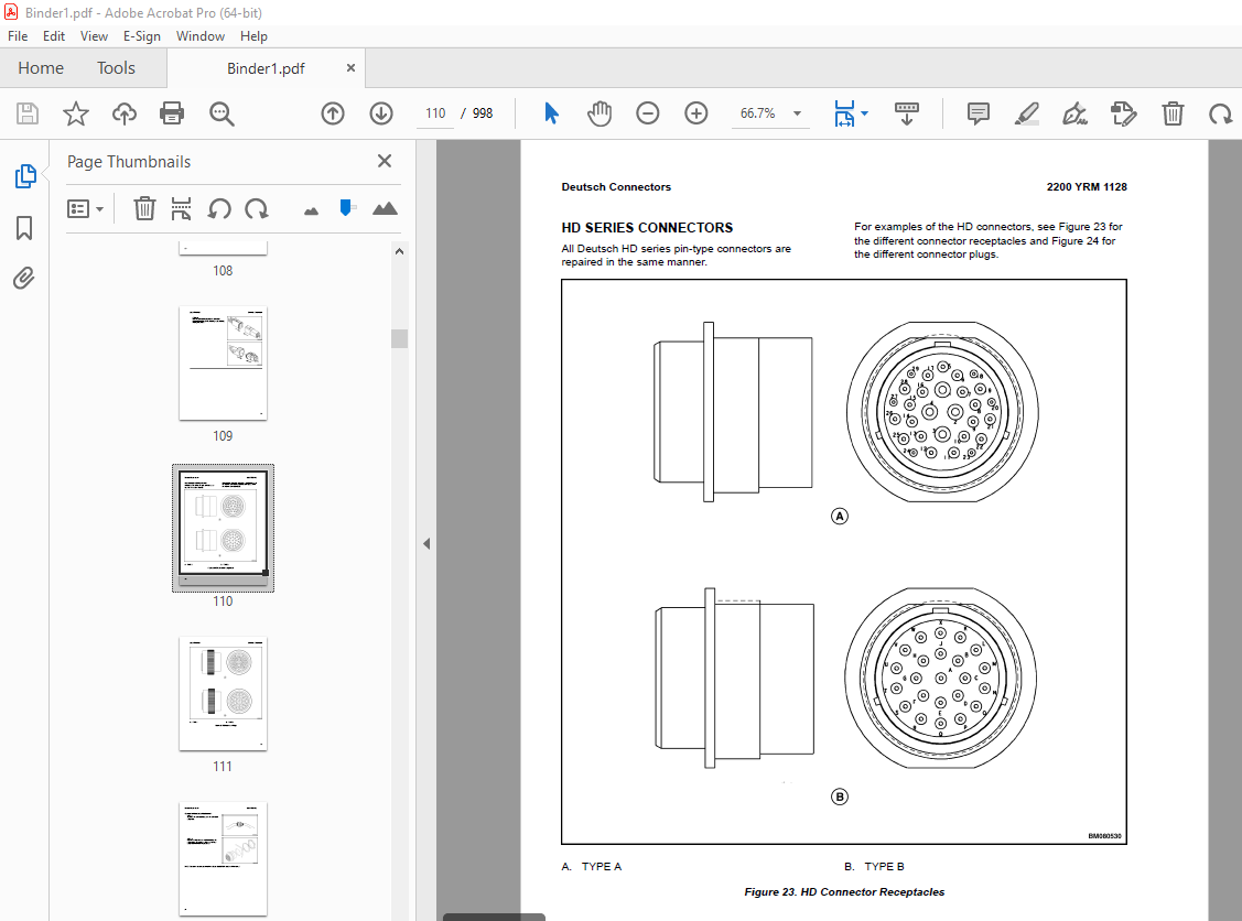
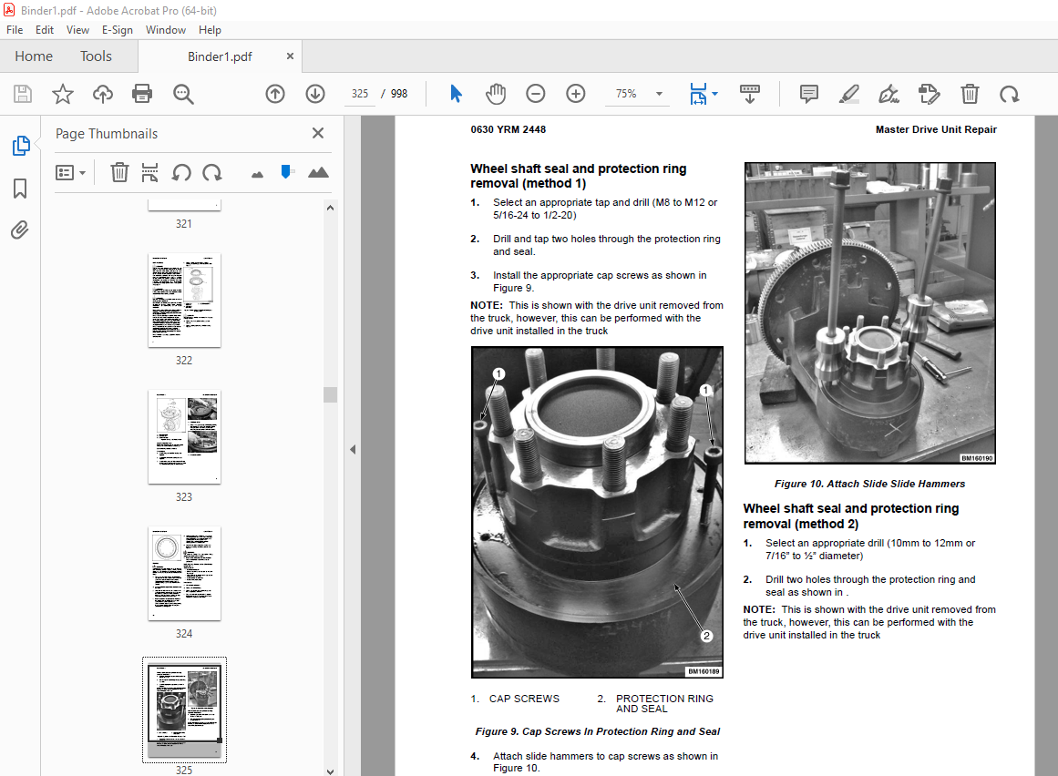
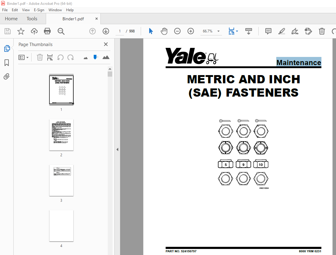
TABLE OF CONTENTS:
Yale Forklift A927 (NR040ECR, NDR030ECR,NDR035ECR, NR045ECR) NEW Service Manual – PDF DOWNLOAD
524150797-8000YRM0231-(02-2023)-UK-EN 1
General 7
Threaded Fasteners 7
Nomenclature, Threads 7
Strength Identification 8
Cotter (Split) Pins 9
Fastener Torque Tables 14
Conversion Table 16
524158040-2240YRM0001-(01-2023)-UK-EN 23
General 29
Battery Type 29
Lead-Acid Batteries 29
Lithium-Ion Batteries 30
Specific Gravity 30
Chemical Reaction in a Cell 30
Electrical Terms 32
Battery Selection 33
Battery Voltage 34
Battery as a Counterweight 34
Battery Ratings 34
Kilowatt-Hours 34
Battery Maintenance 35
Safety Procedures 35
Maintenance Records 35
New Battery 35
Cleaning Battery 36
Adding Water to Battery 38
Hydrometer 38
Battery Temperature 39
Charging Battery 40
Types of Battery Charges 41
Methods of Charging 42
Troubleshooting Charger 43
Knowing When Battery Is Fully Charged 43
Where to Charge Batteries 43
Equipment Needed 43
Battery Connectors 44
Battery Care 44
Troubleshooting 46
524223769-2200YRM1128-(01-2023)-UK-EN 51
Series Code / Model Designation Reference Table 59
General 61
Deutsch Crimping Tool 62
How to Strip a Wire for Use With Deutsch Crimping Tool 62
How to Crimp With the Deutsch Crimping Tool 63
Calibration Test for the Deutsch Crimping Tool 65
Deutsch Connectors 67
DT, DTM, and DTP Series Connectors 67
HD Series Connectors 110
Metri-Pack Connectors 132
Remove and Install 132
Micro-Pack Connectors 135
Weather-Pack Connectors 136
AMPSEAL Crimping Tools 138
AMP Hand Crimping Tool With Certi-Crimp 138
Description 138
Stripping Wire for Use with AMP Hand Crimping Tool 139
Insulation Crimp Adjustment 140
Maintenance and Inspection for AMP Hand Crimping Tool 140
AMP Hand Crimping Tool 140
Crimp Height Inspection 140
How to use AMP Hand Crimping Tool 141
AMP Pro-Crimper II Tool 141
Description 141
Remove and Install Die Set and Locator Assembly 142
Stripping Wire for Use With AMP PRO-CRIMPER II Tool 142
Contact Support Adjustment 143
Crimp Height Adjustment 144
Maintenance and Inspection Procedures 144
PRO-CRIMPER II Tool 144
Crimp Height Inspection 144
How to Use AMP PRO-CRIMPER II Tool 145
AMPSEAL Connector Assemblies 146
Description for Plug Connector Assembly 146
Seal Plug 147
Contact Crimping 147
Description for Plug Connector and Header Assembly 152
Voltage Reading 155
Seal Plug 155
Contact Crimping 155
AMP Superseal 1 5 Crimping Tools 162
Mini Mic Receptacle and Tab Contacts 162
Description 162
Crimping Conditions and Measurements 162
Insertion of Rubber Seal on Cable 164
AMP Hand Application Tool 169
Description 169
Maintenance and Inspection 169
Crimp Height Inspection 169
Crimp Height Adjustment 170
How to Use AMP Hand Application Tool 170
AMP Pro-Crimper II Tool 171
Description 171
Remove and Install Die Set and Locator Assembly 171
Adjustments 172
Contact Support 172
Crimp Height 173
Inspections and Maintenance 174
Crimp Height Inspection 174
Visual Inspection 174
Maintenance 175
How to Use Pro-Crimper II Tool 175
AMP Superseal 1 5 Connector Assemblies 176
Description 176
Repair and Maintenance 183
Panel Mount Option 183
AMP Fastin-Faston Hand Tools 184
Description – AMP Double Action Hand Tool 184
Maintenance and Inspection Procedures 184
Daily Maintenance 184
Periodic Tool Inspection 185
Lubrication 185
Visual Inspection 185
Crimp Height Inspection 185
Certi-Crimp Ratchet Inspection 186
How to Use AMP Double Action Hand Tool 187
Description – AMP Extraction Tool 188
Maintenance and Inspection 189
How to Use AMP Extraction Tool 189
AMP Fastin-Faston Receptacles and Housings 191
Description 191
Wire Repair 199
Wire Splicing Requirements 199
Deutsch Jiffy Splice 200
Twisted/Shielded Cable and Leads Repair 206
Special Tools 208
550191464-0630YRM2084-(09-2022)-UK-EN 217
General 223
General 223
Description 224
Discharging The Capacitors 225
Master Drive Unit Repair 229
Maintenance 229
Draining the Oil 229
Remove 229
Disassemble 231
Clean and Inspect 232
Assemble 232
Install 233
Replace the Wheel Seal on Kordel Drive Units 234
Tools required 234
Truck setup 234
Wheel shaft seal and protection ring removal (method 1) 234
Wheel shaft seal and protection ring removal (method 2) 235
Wheel shaft seal and protection ring installation 236
Troubleshooting 238
550209887-1900YRM2189-(09-2022)-UK-EN 241
General 247
Discharging the Capacitors 250
Description 253
Control Handle 255
Sidestance Control Handle 255
Fore/Aft Stance 256
Maintenance 257
Oil Level and Leaks 257
Operation 257
Oil Change 257
Drain 257
Cylinder Identification 259
Fill 261
Main Lift Cylinders 261
Free-Lift Cylinders 262
Breather Cap 263
Inspect 263
Hydraulic Oil Filter 263
Change 263
Oil Strainer 264
Check 264
Hydraulic System 265
General 265
Cleaning 265
Noise Levels 265
Hoses 265
Fittings 267
Hydraulic Lift Pump and Motor 268
Lift Trucks Equipped With a 25cc or 32cc Hydraulic Pump 268
Remove 268
Disassemble – Lift Trucks Equipped With a 25cc or 32cc Hydraulic Pump 272
Clean 274
Inspect 274
Assemble 274
Install 274
Lift Truck Models Equipped With a 28/9cc Double Hydraulic Pump 276
Remove 276
Disassemble 280
Clean 282
Inspect 282
Assemble 282
Install 282
Manual Lowering Valve 283
Pressure Test Ports 284
Pressure Transducer 285
Relief Valve 286
Lowering Control Valve 287
Auxiliary Hydraulics 288
Reach Carriage Hydraulics 288
Selector Auxiliary Valve 288
Remove 289
Install 289
Auxiliary Manifold 289
Remove 289
Install 289
Auxiliary Direction Control Manifold 289
Remove 291
Install 292
Auxiliary Motor and Pump 292
Remove 293
Disassemble 295
Assemble 296
Install 296
Hydraulic Tank 298
Remove 298
Disassemble 299
Breather Assembly 300
Filter Assembly 300
Tank Fittings 301
Clean and Inspect 302
Assemble 302
Breather Assembly 302
Filter Assembly 302
Tank Fittings 303
Install 303
Specifications 304
Troubleshooting 305
550267564-0630YRM2448-(09-2022)-UK-EN 309
General 315
General 315
Description 315
Discharging The Capacitors 316
Master Drive Unit Repair 320
Maintenance 320
Draining the Oil 320
Remove 320
Disassemble 322
Clean and Inspect 323
Assemble 323
Install 324
Replace the Wheel Seal on Kordel Drive Units 324
Tools required 324
Truck setup 324
Wheel shaft seal and protection ring removal (method 1) 325
Wheel shaft seal and protection ring removal (method 2) 325
Wheel shaft seal and protection ring installation 327
Troubleshooting 328
550273551-0100YRM2471-(09-2022)-UK-EN 331
General 337
Discharging the Capacitors 337
Description 340
Repairs – General 341
Covers, Panels, and Plates 342
Service Access Panel 342
Removal 342
Inspection and Cleaning 343
Installation 343
Operator Compartment Covers 343
Front Covers (Left and Right) 343
Main Cover, Battery Tray Cover (With Tiller Cover), and Service Cover 344
Remove 344
Install 347
Caster Cover 347
Compartment Door Assembly 347
Inspection 348
Door Latch and Stop 348
Remove 348
Inspect 349
Install 349
Adjustment 349
Door Pad 349
Remove 349
Install 350
Operator Back Pad 350
Operator Wall Pad 350
Storage Container 350
Remove 350
Base Arms and Load Wheel Boxes 351
Description 351
Inspection (Bolt-On Wheel Box) 351
Repair 351
Overhead Guard Replacement 352
Remove 354
Inspect 354
Install 354
Light Assemblies 354
Painting and Vinyl Wrap Instructions 355
Painting Instructions 355
Vinyl Wrap 355
Removal 356
Surface Preparation 356
Installation 357
Repair 358
Safety Labels Replacement 359
Frame Fasteners 362
Repair 362
Threaded Insert Removal 362
Inspection 362
Install 362
550273552-0620YRM2472-(09-2022)-UK-EN 365
General 371
Discharging the Internal Capacitors 371
Traction Motor Repair 374
Remove 374
Disassemble 377
Clean/Inspect 382
Assemble 382
Install 383
Hydraulic Motor Repair 385
Auxiliary Motor Repair 393
General 393
Special Tools 394
Tool Chart 394
Troubleshooting 395
550273553-1600YRM2473-(09-2022)-UK-EN 399
General 405
Discharging the Capacitors 406
Raising the Lift Truck 408
How to Raise the Drive Tire End 409
How to Raise the Entire Lift Truck 410
Description 411
Steering Handle Assembly 413
Description 413
Remove (Fixed and Adjustable) 413
Disassemble (Fixed Steering Handle) 414
Assemble (Fixed Steering Handle) 416
Disassemble (Adjustable Steering Handle) 416
Assemble (Adjustable Steering Handle) 419
Install (Fixed and Adjustable) 419
Steering Sensors and Steering Controllers 420
Steering Motor 420
Description 420
Remove 420
Steering Motor 420
Disassemble 422
Assemble 422
Install 422
Steering Motor 423
Caster Assembly – General 424
Caster Adjustment 424
Elastomer Spring Type Adjustment 424
Remove Spring Assembly 426
Replace Spring Pack 427
Install Spring Assembly 427
Proximity Switch Adjustment 428
Caster Wheels 429
Remove 429
Install 429
Caster Wheel Assembly (Non-steered) 431
Description 431
Remove 431
Disassemble 432
Upper and Lower Support Housings 432
Spring Assembly From Lower Support Assembly 433
Caster Spindle From Lower Support 433
Lower Support Housing 434
Upper Support Housing 435
Assemble 435
Upper Support Housing 435
Lower Support Housing 436
Caster Spindle to Lower Support 437
Spring Assembly to Lower Support 437
Upper and Lower Support Housings 437
Install 437
Troubleshooting 439
550273554-1800YRM2474-(09-2022)-UK-EN 441
General 447
Discharging the Capacitors 447
Electric Brake 450
Air Gap 451
Coil Resistance Check 453
Remove 454
Install 454
Troubleshooting 456
550273555-2200YRM2475-(09-2022)-UK-EN 459
General 467
Discharging the Internal Capacitors 468
Static Strap 471
Inspect 471
Replace 471
Safety Procedures When Working Near Mast 472
Automated Battery Charger and Battery Cables 475
Inspect 475
Automated Battery Charger 475
Remove 475
Install 476
Battery Cables 476
Remove 476
Install 477
Manually Charging the Battery 477
Key Switch 478
General 478
Replace 478
Major Electrical System Features 480
General 480
Integrated System 480
CANbus Advantages 480
CANbus Communications 480
Electric Steering 480
Centering Proximity Sensor 480
Traction and Hydraulic Functions 481
Vehicle System Manager 481
Input Devices 481
Output Devices 481
Encoder Integrity 481
Test Encoders 481
Proximity Switches 481
Dash Display Panel 482
BDI 483
Speed 483
Steer Angle 483
Truck Hours 483
Performance Mode 483
HMI Control Box 483
Setup 484
Calibrations 484
AC Motor Controllers and Connecting Cables 485
General 485
Controller Removal 485
Install 487
Low-Voltage Protection Function 489
CDF File Installation Procedure 490
Contactor and Electrical Panel Checks 492
Fuse Panel and Relays 492
Contactors Inspection 493
General 493
Test 494
Tips 495
Replacing The Main Contactor 495
Remove 495
Install 497
Replacing The Freezer Contactor 498
Remove 498
Install 499
Instrument Panel and Dash Display 500
Description 500
Remove 501
Display 502
Install 502
Battery Power Disconnect Switches 503
Replace 503
Multifunction Controls 506
Multifunction Control Handle 506
Horn 506
Inspection 507
Remove 507
Install 509
Multifunction Control Handle Disassembly and Repair 510
Handle Grip and Switch Repairs 510
Handle Grip Support Mounting 510
Handle Disassembly 510
Steering Handle 514
Steering Unit Repair 514
Steering Sensors and Steering Controllers 518
Steering Proximity Sensor 518
Remove 518
Adjust/Install 519
Power Steering Controller 520
Remove 520
Disassemble 521
Assemble 521
Install 522
Brake Switch 523
General 523
Repair, Cushioned and Non-Heated Floor Plate Configuration 523
Repair, Suspended, Non-Heated Floor Plate Configuration 525
Repair, Heated Floor Plate Configuration 526
General 526
Heated Floor Plate Assembly 526
Operator Sensing System 529
General 529
Remove 530
Install 531
Audible Alarm and Horn 532
Horn 532
Audible Alarm 532
Light Assemblies 534
General 534
Front Headlights 535
Remove 535
Install 535
Front Blue Spot Light, Rear Work Light, and Rear Blue Spot Light 536
Remove 536
Install 536
Visible Alarm Light (Strobe Light) 537
Remove 537
Install 537
Light Switches 537
Cooling Fans 538
Electrical Compartment Fans 538
Controller Cooling Fan, Replace 538
Rear Cooling Fan, Replace 539
Vehicle Systems Manager, O-Box, and DC/DC Converter 540
General 540
Vehicle Systems Manager (VSM) 540
Remove 540
Install 541
O-Box (Control Module) 542
Remove 542
Install 544
DC-DC Converter 545
Remove 545
Install 546
Lift Truck Automation System 547
General 547
Preperation 547
Microscan3 Sensors 548
Side Sensors 548
Remove 548
Install 548
Front Sensor 548
Remove 548
Install 549
Rear Sensor 549
Remove 549
Install 550
Adjust Microscan3 Sensor 550
Automated Mid-Range Distance Sensor 551
Replace 551
Height Proximity Switch Option 552
Test 553
Remove 553
Install 553
Reach Carriage Proximity Sensor 555
General 555
Remove 555
Install 556
Adjust 556
Automated Carriage Camera Option 557
Wireless Camera 557
Remove 557
Install 557
Wireless Camera Monitor 558
Remove Monitor Assembly 558
Install Monitor Assembly 559
Automated Lookdown Sensor Option 560
Replace 560
Automated LiDAR Navigation Sensor Option 561
Replace 561
Replace the Power and Communication Wire Harness Cables 561
Remove 561
Install 562
550273556-2200YRM2476-(09-2022)-UK-EN 565
General 575
Menu Navigation 577
Navigation Key 577
Arrow Keys and Scroll Bar 578
Startup Sequence 579
Password Entry 581
Adding/Changing Passwords 581
Home Screen 581
Home Screen Layout 582
Meters 582
Driving Meter 582
Dynamic Meter 583
Center Area 583
Meter Frame 583
Companion Icon 583
Unit Indicator 583
Steer Direction 583
Gauges 584
Menu Structure 588
Password Based Menus 591
Service Logging In 592
Log In 592
Enable/disable password (optional) 593
Main Menus 594
Information Menu 596
Faults Menu 597
Settings Menu 603
Performance Menu 605
Performance Parameters 606
P1 3 Travel Speed FF 606
P1 5 Travel Speed FT 606
P1 9 Travel Acceleration 606
P1 11 Neutral Braking 606
P1 13 Regen Braking 607
P1 15 Lift Speed 607
P1 19 Lower Speed 607
P1 27 Lift Acceleration 607
P1 29 Lower Acceleration 607
P1 31 Lift Deceleration 607
P1 33 Lower Deceleration 607
P1 35 Reach Mech Spd In 607
P1 37 Reach Mech Spd Out 607
P1 43 Tilt Speed Forward 607
P1 45 Tilt Speed Back 607
P1 53 Sideshift Speed 607
P1 67 Aft Handle Speed FF 608
P1 69 Aft Handle Speed FT 608
P1 71 Aft Handle Regen Braking 608
P1 73 Steer Ratio 608
Hydraulic Menu 608
Hydraulic Parameter Adjustments 608
H1 25 Carry Ht Mode 608
H1 27 Carry Ht Horn Duration 608
H2 3 RTST 608
H2 5 RTST Pause Duration 608
H2 7 RTST Override Mode 608
H2 19 RTST Stop Direction 609
H3 15 Auto Center SS 609
H9 15 Hydraulic Lockout 609
Drive Menu 609
Drive Parameter Adjustments 611
D2 1 Type 611
D2 9 BDI Reset 611
D2 11 Lift INT – Battery 611
D2 21 Ahr Capacity 611
D2 25 BDI Adjust 611
D2 39 Battery Gate Switch (Sw) 611
D4 1 Steer Effort 611
D4 3 Steer Mode 611
D4 51 Steer Speed Red En 612
D4 53 Steer Speed Red 612
D8 2 Mast Up FT Speed Limit 612
D8 3 Carr Ext Spd Red 612
D8 4 FF Spd w/Carr Ext 612
D8 5 FT Spd w/Carr Ext 612
D8 13 Simultaneity Mode 612
D8 55 Mast Up FF Speed Limit 612
Sensors/Presets Menu 612
Sensor/Presets Parameters 613
S1 1 Impact Sensor 613
S1 3 Impact OP (Operator Presence) Filter 613
S1 5 Impact Logging 613
S1 7 Mark Events Crit (Criteria) 613
S1 9 Impact Shutdown 613
S1 11 Shutdown Timeout 613
S1 13 Impact Audible Alarm 613
S1 15 Impact Visual Alarm 613
S1 17 Hard Impacts/Day 613
S1 19 Soft Impacts/Day 613
S1 21 Clear Derate Event 613
S1 23 Soft Count Threshold 613
S1 25 Soft Impact Threshold Horizontal 613
S1 27 Soft Impact Threshold Vertical 613
S1 29 Hard Impact Threshold Horizontal 613
S1 31 Hard Impact Threshold Vertical 614
Shutdown Impact Threshold Horizontal 614
Shutdown Impact Threshold Vertical 614
S3 1 Camera 1 614
S3 5 Fork Laser 614
S4 1 Shelf Height 614
S4 3 Place Offset 614
S4 5 Preset Ht (Height) 614
S4 25 Lift/Low Limit 614
S4 26 Limit Override 614
S4 27 Lift/Low Limit En 614
S4 45 Fork Height Disp 614
S5 7 Connection Type 614
Maintenance Menu 615
Maintenance Parameters 617
M1 1 Reminder Levels 617
M1 3 Level 1 617
M1 5 Level 2 617
M1 7 Level 3 617
M1 9 Level 4 617
M1 11 Level 5 617
M1 13 Level 6 617
M1 15 Derate Speed 617
M1 17 Hours Until Derate 617
M1 19 Reset All 617
M1 21 Disable All 617
M2 1 Checklist 617
M2 3 Checklist Frequency 617
M2 5 Operator Options 617
M2 7 Technical Access 617
M2 9 Shift 1 Start Time 617
M2 11 Shift 2 Start Time 617
M2 13 Shift 3 Start Time 617
M2 15 Shift 4 Start Time 617
M2 17 Question Time Limit 617
M2 19 No Response Shutdown 617
M2 21 Pre Start Overtime 618
M2 23 Post Start Overtime 618
M2 25 Pre Shutdown 618
M2 27 Post Shutdown 618
Truck Setup 618
Setting Time and Date 620
Truck Setup Parameters 621
T1 1 Units 621
T1 3 Languages 621
T1 5 Time 621
T1 7 Time Format 621
T1 15 Service Lockout 621
T1 23 Brightness 621
T1 25 Auto Dim 621
T1 50 Restore Defaults 621
T2 21 Front Blue Lt 621
T2 23 Rear Blue Lt 621
T4 5 Audible Alarm 621
Operators Menu 622
Adding New Operator 622
Adjusting Existing Operator Parameters 623
Operator Parameters 623
O1 5 Access Level 623
O1 7 Delete 623
O1 9 Allowed Performance Modes 624
Calibrations Menu 624
Calibration Parameters 626
H2c Tilt 626
H2c 3 RTST Calibration 626
H2c 11 Tilt Calibration 626
D5c Steer Axle 626
D5c 5 Steer Motor Calibration 626
D12c Throttle 626
D12c 3 Aft Throttle Range 626
S8c Height Sensor 626
S8c 1 Mast Height Calibration 626
S8c 5 Lift Enc Zero Pos 626
S12c Load Weight 627
S12c 1 Weight Scale Calibration 627
Diagnostics Menu 627
Diagnostic Parameters 630
C1d VSM/Contactor 630
C1d 1 Electronic Out 1 630
C1d 3 Electronic Out 2 630
C1d 5 Main Contactor 630
C5d Switches/Buttons 630
C5d 1 Horn Switch 630
C5d 11 Audible Alarm 630
C5d 14 Left Batt Gate SW 630
C5d 15 Right Batt Gate SW 630
C6d Occupancy 630
C6d 3 Egress Curtain 630
C6d 5 OP Left Leg Sensor 630
C6d 7 OP Right Leg Sensor 631
Current/Voltage 631
C7d 3 Power Voltage 631
C7d 4 Power Current 631
C7d 5 Sensor Voltage 631
C7d 7 Out 1 Voltage 631
C7d 8 Out 1 Current 631
C7d 9 Out 2 Voltage 631
C7d 10 Out 2 Current 631
C7d 11 Out 3 Voltage 631
C7d 12 Out 3 Current 631
C7d 13 Out 4 Voltage 631
C7d 14 Out 4 Current 631
C7d 15 Out 5 Voltage 631
C7d 17 Out 6 Voltage 631
C7d 18 Out 5 and 6 Current 631
C7d 19 Out 7 Voltage 631
C7d 21 Out 8 Voltage 631
C7d 22 Out 7 and 8 Current 631
C7d 23 Out 9 Voltage 631
C7d 25 Out 10 Voltage 631
C7d 26 Out 9 and 10 Current 631
C7d 27 In 1 Voltage 631
C7d 29 In 2 Voltage 631
C7d 31 In 3 Voltage 631
D2d Battery 631
D2d 1 Battery Voltage 631
D2d 3 State of Charge (SOC) 631
D4d Steer 632
D4d 3 Steer Angle 632
D4d 7 Steer Status 632
D4d 11 Controller Temp 632
D4d 12 Motor Temp 632
D4d 13 Motor Current 632
D4d 14 Cap Voltage 632
D4d 15 Cap Max Voltage 632
D4d 16 Cap Min Voltage 632
D4d 17 Key Voltage 632
D4d 18 Key Max Voltage 632
D4d 19 Key Min Voltage 632
D4d 20 Center Proximity Switch 632
D6d Steer (Caster) 632
D6d 3 Steer Angle 632
D6d 7 Steer Status 632
D6d 11 Controller Temperature 632
D6d 12 Motor Temperature 632
D6d 13 Motor Current 632
D6d 14 Cap Voltage 632
D6d 15 Max Cap Voltage 632
D6d 16 Min Cap Voltage 632
D6d 17 Key Voltage 632
D6d 18 Max Key Voltage 632
D6d 19 Min Key Voltage 632
D6d 20 Center Prox Switch 632
D8d Traction 632
D8d 2 Travel Speed 632
D8d 7 Motor 1 Target Speed 632
D8d 9 Motor 1 Speed 632
D8d 13 Controller 1 Temperature 633
D8d 15 Motor 1 Temperature 633
D8d 17 Motor 1 Current 633
D8d 19 Controller 1 Cap Volts 633
D8d 21 Controller 1 Cap Max Volts 633
D8d 23 Controller 1 Cap Min Volts 633
D8d 25 Controller 1 Key Volts 633
D8d 27 Controller 1 Key Max Volts 633
D8d 29 Controller 1 Key Min Volts 633
D8d 35 Brake Switch 633
D8d 41 Aft Throttle 633
D8d 43 Aft Enable Switch 633
D8d 45 Aft Horn Switch 633
H1d Lift/Lower 633
H1d 7 Lift Pressure 633
H1d 9 Lift Command 633
H1d 13 Function Switch 633
H1d 29 Prop Coil Current 633
H1d 41 Mast Prox Switch 633
H1d 43 Lift Height Sensor 633
H1d 45 Hoist Select Coil Status 633
H1d 47 Lift Coil Status 633
H1d 49 Load Hold Coil Status 633
H2d Tilt 633
H2d 4 Command 633
H2d 17 Tilt Coil Status 633
H3d 3rd Hydraulic Function 633
H3d 4 3rd Command 633
H3d 15 Return Position Proximity Sensor 633
H3d 17 3rd Hydraulic Coil Status 633
H4d 4th Hydraulic Function 634
H4d 4 4th Command 634
H4d 15 4th Hydraulic Coil Status 634
H8d Pump 634
H8d 1 Controller Temp 634
H8d 3 Motor Temp 634
H8d 5 RMS Motor Current 634
H8d 11 Target Motor Speed 634
H8d 13 Motor Speed 634
H8d 31 Mast Prox Switch 634
H8d 33 Aux Motor Target Speed 634
H8d 35 Aux Motor Speed 634
H8d 37 Aux Motor Temperature 634
H8d 39 Aux Motor Current 634
Hour Meters 635
View Hour Meters 635
Hardware and Software Versions 636
View Hardware and Software Versions 636
Interlocks 637
General 637
Switched Inputs and Preset Heights 639
General 639
Setting Preset Heights 640
550273558-4000YRM2478-(09-2022)-UK-EN 645
General 651
Description 653
Lowering Control Valve 654
Safety Procedures When Working Near Mast 656
Main Lift Cylinder Repair 658
Remove 658
Disassemble 659
Clean and Inspect 661
Clean 661
Inspect 661
Assemble 661
Install 663
Main Lift Cylinder Leak Check 663
Free-Lift Cylinder Repair 664
Remove 664
Disassemble 666
Clean 668
Inspect 668
Assemble 668
Install 669
Sideshift Cylinder Repair 670
General 670
Remove 670
Disassemble 671
Clean and Inspect 672
Assemble 672
Install 672
Reach Cylinder Repair 673
Remove 673
Disassemble 674
Clean and Inspect 676
Assemble 676
Install 676
Reach Cylinder Adjustments 678
Tilt Cylinder 679
Lift Chains 679
Clean and Inspect 679
Troubleshooting 681
550273559-4000YRM2479-(09-2022)-UK-EN 683
General 689
Safety Procedures When Working Near Mast 692
Mast Weldments 695
Reach Carriage Assembly 697
550273560-4000YRM2480-(09-2022)-UK-EN 701
General 707
Safety Procedures When Working Near Mast 710
Load Backrest 713
Remove 713
Install 713
Forks 714
Remove 714
Install 715
Flapper Assembly 715
Remove 715
Disassemble 716
Assemble 717
Install 717
Checks 717
Hose And Chain Sheaves 719
General 719
Hose Sheaves 722
Remove 722
Lift Trucks Equipped With E570 Short Mast 722
Lift Trucks Equipped With D585 Tall Mast 727
Clean and Inspect 729
Install 729
Lift Trucks Equipped With E570 Short Mast 729
Lift Trucks Equipped With D585 Tall Mast 730
Main Lift Chain Sheaves 731
Remove 731
Lift Trucks Equipped With E570 Short Mast 731
Lift Trucks Equipped With D585 Tall Mast 731
Clean and Inspect 733
Install 733
Lift Trucks Equipped With E570 Short Mast 733
Lift Trucks Equipped With D585 Tall Mast 733
Free-Lift Chain Sheaves 734
Remove 734
Left Chain Sheave 734
Right Chain Sheave 735
Install 736
Left Chain Sheave 736
Right Chain Sheave 736
Load Rollers 737
Mast Load Rollers 737
Remove 739
Clean and Inspect 741
Install 741
Reach Carriage Assembly 742
Reach Carriage Assembly Remove and Install 743
Description 743
Remove 744
Inspect 748
Install 748
Mast Repair 750
Remove 750
Disassemble 757
Wear Strips and Shims 758
Clean and Inspect 759
Assemble 760
Install 761
Mast Lubrication 763
Header Hose Installation and Adjustment 763
Remove 763
Installation 764
Lift Chains 770
Clean and Inspect 770
Mast Adjustments 771
General 771
Mast Back Angle Adjustment 771
Adjust Main-Lift Chains 772
Adjust Free-Lift Chain 773
Adjust Wear Strips 775
Mast Side Kicking (Racking) 775
Wear Pad Adjustments 776
Proximity Switches 777
Mast Operation Check 778
550273561-4500YRM2481-(09-2022)-UK-EN 781
General 787
Safety Procedures When Working Near Mast 788
Description 791
Load Backrest 793
Remove 793
Install 793
Forks 794
Remove 794
Install 795
Flapper Assembly 795
Remove 795
Disassemble 796
Assemble 797
Install 797
Checks 797
Load Rollers 799
Remove 799
Clean and Inspect 801
Install 801
Reach Carriage Assembly Repair 802
General 802
Reach Carriage Front Frame 802
Remove 802
Disassemble 809
Clean and Inspect 813
Assemble 813
Install 814
Single-Reach Scissor Arms 814
Remove 814
Disassemble 814
Wear Strip – Inspect and Replacement 816
Remove 816
Install 818
Clean and Inspect 818
Assemble 818
Double-Reach Scissor Arms 818
General 818
Disassemble 819
Clean and Inspect 822
Assemble 822
Install 823
Reach Carriage Rear Frame 823
Remove 823
Disassemble 823
Clean and Inspect 824
Assemble 825
Install 825
Reach Carriage Adjustments 826
General 826
Check Adjustment 826
Wear Pads Adjustment 826
Free-Lift Chain Adjustment 826
Cylinders Adjustments 826
Reach Carriage Bumper Adjustment 827
Inner Arm Lateral Adjustment 828
Proximity Sensor Lateral Adjustment 829
Lower Hook Adjustment 830
Carriage Stroke Adjustment 831
Lift Chains 833
Specifications 833
Troubleshooting 834
550273562-8000YRM2482-(09-2022)-UK-EN 837
General 843
Preparation for Use 844
Discharging the Internal Capacitors 845
Covers and Doors 848
Remove 848
Install 851
Manual Lowering Valve 852
How to Move Disabled Truck 853
How to Put Lift Truck on Blocks 855
How to Raise Load Wheels 855
How to Raise the Drive Tire End 856
How to Raise the Entire Lift Truck 857
Transporting 858
Loading 858
Unloading 858
Safety Procedures When Working Near Mast 859
Maintenance Schedule 862
Maintenance Procedures Every 8 Hours or Daily 872
Checks With Key Switch Turned OFF 872
Hydraulic System 872
Forks 873
Forks, Remove 873
Forks, Check 873
Forks, Install 875
Forks, Adjust 875
Inspection of Mast and Lift Chains 875
Reach, Tilt, and Sideshift 876
Caster Adjustment 876
Safety Labels 876
Battery 877
Tires and Wheels 877
Frame and Load Wheels 878
Overhead Guard 878
Static Strap 878
Checks With Key Switch Turned ON 879
Horn and Battery Indicator 879
Fuses and Relays 879
Operation 880
Control Levers and Pedals 881
Lift System Operation 881
Multifunction Control Handle 882
Brake 882
Steering System 883
Maintenance Procedures Every 500 Hours or 3 Months 884
Hydraulic System 884
Hydraulic Filter Change 885
Master Drive Unit 887
Adding Oil To Master Drive Unit (MDU) 887
Changing Oil In Master Drive Unit (MDU) 887
Caster Adjustment 890
Elastomer Spring Type Adjustment 890
Spring Pack Replacement 893
Remove Spring Assembly 893
Replace Spring Pack 893
Install Spring Assembly 894
Load Wheels 894
Drive Tire Check 896
Lift System Operation 896
Forks 896
Mast 897
Lift Chains 897
Electrical System 898
Power Cables and Electrical Connections 898
Other Lubrication 898
Maintenance Procedures Every 2000 Hours or Yearly 899
Electric System 899
Main Contactor 899
Inspect 899
Freezer Contactor 900
Remove 900
Install 901
Hydraulic System 902
Drain 902
Cylinder Identification 903
Fill 904
Main Lift Cylinders 904
Free-Lift Cylinders 905
Hydraulic Filter Change 906
Check Hydraulic Strainer 907
Battery Maintenance 908
How to Charge Battery 908
How to Change Battery 909
Lift and Tilt System Leaks Check 912
Lift System 912
Tilt System 912
Tires and Wheels 913
Drive Tire 913
How to Change Drive Tire 913
Load Wheels, Bolt-On Wheel Box 914
Caster Wheels 916
Remove 916
Install 917
Preparation for Storage 918
Short-Term Storage (1 to 6 months) 918
Long-Term Storage (6 months or longer) 918
550273563-8000YRM2483-(09-2022)-UK-EN 921
Lubrication Specifications 927
Oil Capacities 927
Hydraulic System 927
Mast Speeds 928
Carriage Speeds 930
Carriage Operating Times 932
Forks 933
Steering System 933
Brake System 934
Traction Motor Speeds 935
Tire Sizes 936
Torque Specifications 937
Master Drive Unit 937
Reach Carriage 937
Mast 937
Hydraulic System 937
Steering System 937
Load Wheels 937
Fuses 938
Coil Resistance Values 939
Battery Specifications 940
550273564-8000YRM2485-(09-2022)-UK-EN 943
Schematic/Diagram 949
Electrical Schematics 949
Hydraulic Schematics 965
550276785-9000YRM2486-(09-2022)-UK-EN 971
Error code reference charts 975
Vehicle System Manager (VSM) Error Code Reference Chart 975
More products