$43.95
Yale Forklift A955 (ERP030-040VF) Service Manual - PDF
Yale Forklift A955 (ERP030-040VF) Service Manual – PDF DOWNLOAD
FILE DETAILS:
Yale Forklift A955 (ERP030-040VF) Service Manual – PDF DOWNLOAD
Language : English
Pages : 4056
Downloadable : Yes
File Type : PDF
IMAGES PREVIEW OF THE MANUAL:
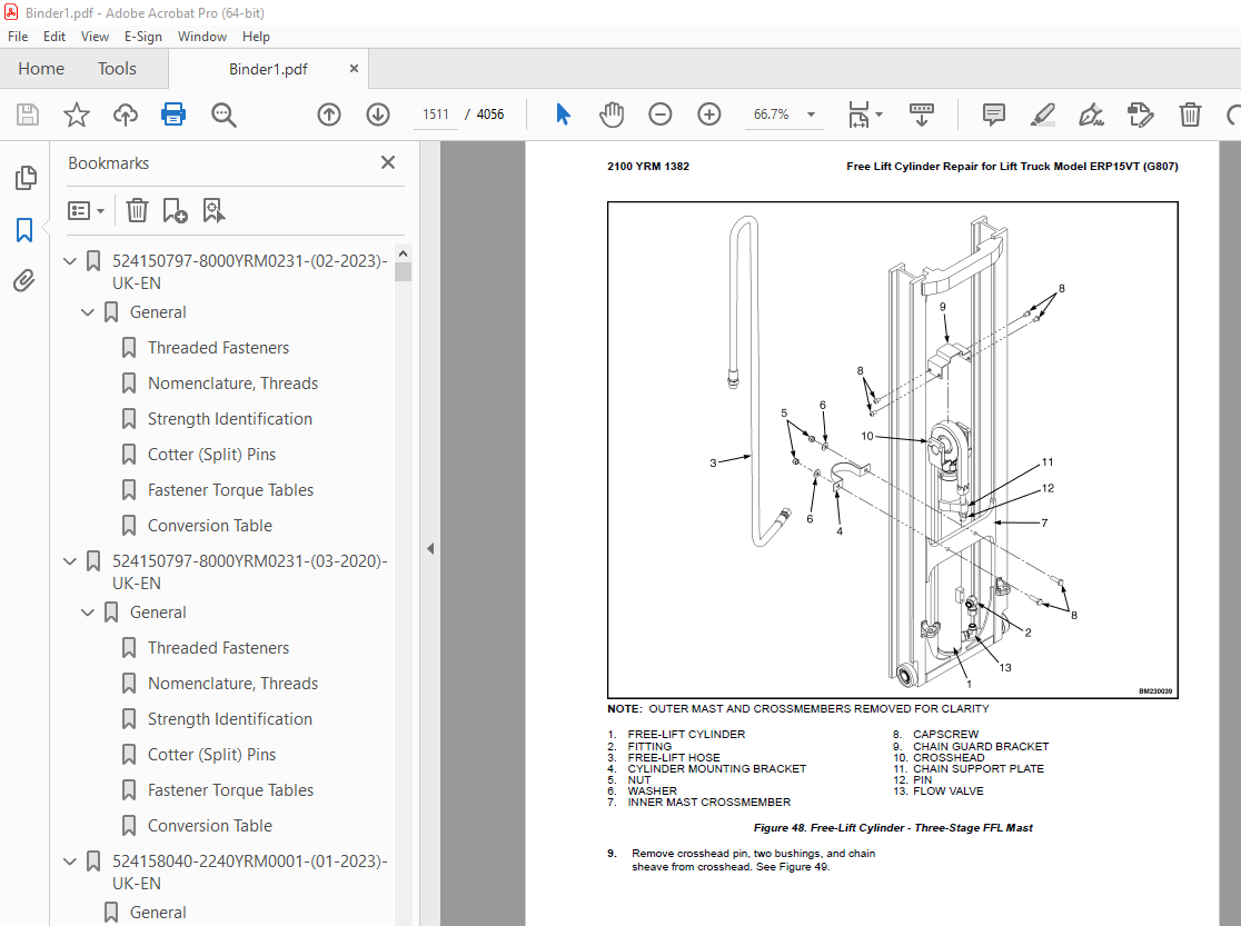
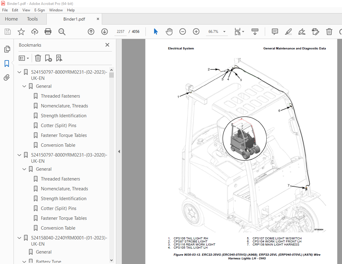
TABLE OF CONTENTS:
Yale Forklift A955 (ERP030-040VF) Service Manual – PDF DOWNLOAD
524150797-8000YRM0231-(02-2023)-UK-EN 1
General 7
Threaded Fasteners 7
Nomenclature, Threads 7
Strength Identification 8
Cotter (Split) Pins 9
Fastener Torque Tables 14
Conversion Table 16
524150797-8000YRM0231-(03-2020)-UK-EN 23
General 27
Threaded Fasteners 27
Nomenclature, Threads 27
Strength Identification 28
Cotter (Split) Pins 29
Fastener Torque Tables 34
Conversion Table 36
524158040-2240YRM0001-(01-2023)-UK-EN 43
General 49
Battery Type 49
Lead-Acid Batteries 49
Lithium-Ion Batteries 50
Specific Gravity 50
Chemical Reaction in a Cell 50
Electrical Terms 52
Battery Selection 53
Battery Voltage 54
Battery as a Counterweight 54
Battery Ratings 54
Kilowatt-Hours 54
Battery Maintenance 55
Safety Procedures 55
Maintenance Records 55
New Battery 55
Cleaning Battery 56
Adding Water to Battery 58
Hydrometer 58
Battery Temperature 59
Charging Battery 60
Types of Battery Charges 61
Methods of Charging 62
Troubleshooting Charger 63
Knowing When Battery Is Fully Charged 63
Where to Charge Batteries 63
Equipment Needed 63
Battery Connectors 64
Battery Care 64
Troubleshooting 66
524158040-2240YRM0001-(03-2020)-UK-EN 71
General 75
Battery Type 75
Lead-Acid Batteries 75
Lithium-Ion Batteries 76
Specific Gravity 76
Chemical Reaction in a Cell 76
Electrical Terms 78
Battery Selection 78
Battery Voltage 79
Battery as a Counterweight 80
Battery Ratings 80
Kilowatt-Hours 80
Battery Maintenance 80
Safety Procedures 80
Maintenance Records 81
New Battery 81
Cleaning Battery 81
Adding Water to Battery 83
Hydrometer 84
Battery Temperature 85
Charging Battery 86
Types of Battery Charges 86
Methods of Charging 88
Troubleshooting Charger 88
Knowing When Battery Is Fully Charged 89
Where to Charge Batteries 89
Equipment Needed 89
Battery Connectors 90
Battery Care 90
Troubleshooting 92
524223769-2200YRM1128-(01-2023)-UK-EN 97
Series Code / Model Designation Reference Table 105
General 107
Deutsch Crimping Tool 108
How to Strip a Wire for Use With Deutsch Crimping Tool 108
How to Crimp With the Deutsch Crimping Tool 109
Calibration Test for the Deutsch Crimping Tool 111
Deutsch Connectors 113
DT, DTM, and DTP Series Connectors 113
HD Series Connectors 156
Metri-Pack Connectors 178
Remove and Install 178
Micro-Pack Connectors 181
Weather-Pack Connectors 182
AMPSEAL Crimping Tools 184
AMP Hand Crimping Tool With Certi-Crimp 184
Description 184
Stripping Wire for Use with AMP Hand Crimping Tool 185
Insulation Crimp Adjustment 186
Maintenance and Inspection for AMP Hand Crimping Tool 186
AMP Hand Crimping Tool 186
Crimp Height Inspection 186
How to use AMP Hand Crimping Tool 187
AMP Pro-Crimper II Tool 187
Description 187
Remove and Install Die Set and Locator Assembly 188
Stripping Wire for Use With AMP PRO-CRIMPER II Tool 188
Contact Support Adjustment 189
Crimp Height Adjustment 190
Maintenance and Inspection Procedures 190
PRO-CRIMPER II Tool 190
Crimp Height Inspection 190
How to Use AMP PRO-CRIMPER II Tool 191
AMPSEAL Connector Assemblies 192
Description for Plug Connector Assembly 192
Seal Plug 193
Contact Crimping 193
Description for Plug Connector and Header Assembly 198
Voltage Reading 201
Seal Plug 201
Contact Crimping 201
AMP Superseal 1 5 Crimping Tools 208
Mini Mic Receptacle and Tab Contacts 208
Description 208
Crimping Conditions and Measurements 208
Insertion of Rubber Seal on Cable 210
AMP Hand Application Tool 215
Description 215
Maintenance and Inspection 215
Crimp Height Inspection 215
Crimp Height Adjustment 216
How to Use AMP Hand Application Tool 216
AMP Pro-Crimper II Tool 217
Description 217
Remove and Install Die Set and Locator Assembly 217
Adjustments 218
Contact Support 218
Crimp Height 219
Inspections and Maintenance 220
Crimp Height Inspection 220
Visual Inspection 220
Maintenance 221
How to Use Pro-Crimper II Tool 221
AMP Superseal 1 5 Connector Assemblies 222
Description 222
Repair and Maintenance 229
Panel Mount Option 229
AMP Fastin-Faston Hand Tools 230
Description – AMP Double Action Hand Tool 230
Maintenance and Inspection Procedures 230
Daily Maintenance 230
Periodic Tool Inspection 231
Lubrication 231
Visual Inspection 231
Crimp Height Inspection 231
Certi-Crimp Ratchet Inspection 232
How to Use AMP Double Action Hand Tool 233
Description – AMP Extraction Tool 234
Maintenance and Inspection 235
How to Use AMP Extraction Tool 235
AMP Fastin-Faston Receptacles and Housings 237
Description 237
Wire Repair 245
Wire Splicing Requirements 245
Deutsch Jiffy Splice 246
Twisted/Shielded Cable and Leads Repair 252
Special Tools 254
524223769-2200YRM1128-(07-2020)-UK-EN 263
Series Code / Model Designation Reference Table 269
General 272
Deutsch Crimping Tool 272
How to Strip a Wire for Use With Deutsch Crimping Tool 272
How to Crimp With the Deutsch Crimping Tool 273
Calibration Test for the Deutsch Crimping Tool 275
Deutsch Connectors 277
DT, DTM, and DTP Series Connectors 277
HD Series Connectors 319
Metri-Pack Connectors 342
Remove and Install 342
Micro-Pack Connectors 344
Weather-Pack Connectors 345
AMPSEAL Crimping Tools 347
AMP Hand Crimping Tool With Certi-Crimp 347
Description 347
Stripping Wire for Use with AMP Hand Crimping Tool 347
Insulation Crimp Adjustment 348
Maintenance and Inspection for AMP Hand Crimping Tool 348
AMP Hand Crimping Tool 348
Crimp Height Inspection 348
How to use AMP Hand Crimping Tool 349
AMP Pro-Crimper II Tool 349
Description 349
Remove and Install Die Set and Locator Assembly 350
Stripping Wire for Use With AMP PRO-CRIMPER II Tool 351
Contact Support Adjustment 351
Crimp Height Adjustment 352
Maintenance and Inspection Procedures 352
PRO-CRIMPER II Tool 352
Crimp Height Inspection 352
How to Use AMP PRO-CRIMPER II Tool 353
AMPSEAL Connector Assemblies 354
Description for Plug Connector Assembly 354
Seal Plug 355
Contact Crimping 355
Description for Plug Connector and Header Assembly 360
Voltage Reading 362
Seal Plug 362
Contact Crimping 362
AMP Superseal 1 5 Crimping Tools 369
Mini Mic Receptacle and Tab Contacts 369
Description 369
Crimping Conditions and Measurements 369
Insertion of Rubber Seal on Cable 371
AMP Hand Application Tool 376
Description 376
Maintenance and Inspection 376
Crimp Height Inspection 376
Crimp Height Adjustment 377
How to Use AMP Hand Application Tool 377
AMP Pro-Crimper II Tool 378
Description 378
Remove and Install Die Set and Locator Assembly 379
Adjustments 379
Contact Support 379
Crimp Height 380
Inspections and Maintenance 381
Crimp Height Inspection 381
Visual Inspection 381
Maintenance 382
How to Use Pro-Crimper II Tool 382
AMP Superseal 1 5 Connector Assemblies 383
Description 383
Repair and Maintenance 390
Panel Mount Option 390
AMP Fastin-Faston Hand Tools 391
Description – AMP Double Action Hand Tool 391
Maintenance and Inspection Procedures 391
Daily Maintenance 391
Periodic Tool Inspection 392
Lubrication 392
Visual Inspection 392
Crimp Height Inspection 392
Certi-Crimp Ratchet Inspection 393
How to Use AMP Double Action Hand Tool 394
Description – AMP Extraction Tool 395
Maintenance and Inspection 395
How to Use AMP Extraction Tool 396
AMP Fastin-Faston Receptacles and Housings 397
Description 397
Wire Repair 404
Wire Splicing Requirements 404
Deutsch Jiffy Splice 405
Twisted/Shielded Cable and Leads Repair 410
Special Tools 413
524295629-0100YRM1329-(04-2023)-UK-EN 421
Introduction 427
General 427
Description of Operation 428
Discharging the Capacitors 429
Rapid Charge 429
Covers and Floor Plates 430
Overhead Guard Replacement 433
Remove 433
Install 438
Hood and Seat Assembly 439
Remove 442
Install 444
Ground Test 444
Counterweight Replacement 445
Remove 446
Install 451
Safety Labels 453
Painting Instructions 458
Battery Specifications 459
European Model Trucks ERP15-20VT (G807) 459
US Model Trucks ERP030-040VT (G807) 460
European Model Trucks ERP16-20VF (A955) 461
US Model Trucks ERP30-40VF (A955) 462
524295629-0100YRM1329-(09-2014)-UK-EN 465
524295630-1300YRM1330-(04-2023)-UK-EN 507
General 513
Discharging the Capacitors 514
Special Tools 514
Transaxle Assembly 515
Remove Transaxle From Frame 515
Remove the Parking Brake and Traction Motor 516
Install Parking Brake and Traction Motor 517
Install Transaxle to Frame 518
Maintenance and Repair 519
Speed Sensor Repair 519
Trunnion Cap Repair 520
Fluid Level Check 520
Fluid Change 521
Breather Repair 522
Stud Repair 523
Brake Cylinder Repair 524
Input Seal Repair 526
Cover to Housing Seal 526
During the Transaxle Warranty Period 526
After the Transaxle Warranty Period 527
Removing the Cover 527
Installing the Cover 528
Wet Brakes 529
Electronic Brake (E-Brake) 531
524295630-1300YRM1330-(10-2015)-UK-EN 533
General 537
Discharging the Capacitors 538
Special Tools 538
Transaxle Assembly 538
Remove Transaxle From Frame 539
Remove the Parking Brake and Traction Motor 540
Install Parking Brake and Traction Motor 541
Install Transaxle to Frame 542
Maintenance and Repair 542
Speed Sensor Repair 542
Trunnion Cap Repair 543
Fluid Level Check 544
Fluid Change 545
Breather Repair 546
Stud Repair 547
Brake Cylinder Repair 548
Input Seal Repair 549
Cover to Housing Seal 550
During the Transaxle Warranty Period 551
After the Transaxle Warranty Period 552
Removing the Cover 552
Installing the Cover 552
Wet Brakes 553
Electronic Brake (E-Brake) 555
524295632-1800YRM1332-(04-2023)-UK-EN 559
Introduction 565
General 565
Discharging the Capacitors 566
Brake Pedal Assembly Repair 567
Hydraulic Brake System 567
Remove 567
Disassemble 568
Assemble 568
Install 568
Electronic Brake (E-Brake) System 569
Remove 569
Disassemble 570
Assemble 571
Install 572
Adjustments 572
Brake Pedal Adjustment 572
Clevis Adjustment 572
Master Cylinder Repair 574
Remove 574
Disassemble 575
Clean and Inspect 577
Assemble 577
Install 577
Adjustments 578
Bleed the Brake System 578
Adjust Linkage 578
Brake Lines 580
Brake Line Replacement 580
Parking Brake 581
Manual Release Lever 581
Adjust Cable 581
Replace Cable 581
Remove 582
Install 583
524295632-1800YRM1332-(11-2015)-UK-EN 585
Introduction 589
General 589
Discharging the Capacitors 589
Brake Pedal Assembly Repair 590
Hydraulic Brake System 590
Remove 590
Disassemble 591
Assemble 592
Install 592
Electronic Brake (E-Brake) System 593
Remove 593
Disassemble 594
Assemble 595
Install 596
Adjustments 596
Brake Pedal Adjustment 596
Clevis Adjustment 596
Master Cylinder Repair 598
Remove 598
Disassemble 598
Clean and Inspect 602
Assemble 602
Install 602
Adjustments 602
Bleed the Brake System 602
Adjust Linkage 603
Brake Lines 603
Brake Line Replacement 604
Parking Brake 605
Manual Release Lever 605
Adjust Cable 605
Replace Cable 605
Remove 606
Install 607
524295633-1900YRM1333-(07-2023)-UK-EN 611
General 617
Hydraulic Pump Repair 618
Remove 618
Disassemble 622
Inspect 624
Clean 624
Assemble 624
Install 624
Hydraulic Tank Assembly 626
Remove 626
Disassemble 628
Clean 629
Steam Method 629
Chemical Method 629
Inspect 630
Assemble 630
Install 630
Hydraulic Filter Replacement 631
Breather Clean and Inspect 632
Add Hydraulic Oil 633
Steer Accumulator Replacement for Lift Truck Models ERP030-40VF (A955) 634
Remove 634
Install 636
Specifications 637
524295633-1900YRM1333-(10-2015)-UK-EN 639
General 643
Hydraulic Pump Repair 644
Remove 644
Disassemble 647
Inspect 649
Clean 649
Assemble 649
Install 649
Hydraulic Tank Assembly 650
Remove 650
Disassemble 653
Clean 653
Steam Method 654
Chemical Method 654
Inspect 654
Assemble 654
Install 655
Hydraulic Filter Replacement 656
Breather Clean and Inspect 657
Add Hydraulic Oil 657
Steer Accumulator Replacement for Lift Truck Models ERP030-40VF (A955) 658
Remove 658
Install 658
Specifications 661
524319491-1600YRM1360-(03-2023)-UK-EN 665
General 673
Steering Axle Assembly Repair 675
Remove ERC22-35VG (ERC045-070VG) (A968), ERC16-20VA (ERC030-040VA) (A969) and ERC40-55VH, ERC50VHS (ERC80-120VH, ERC100VHS) (A938) 675
Disassemble ERC22-35VG (ERC045-070VG) (A968), ERC16-20VA (ERC030-040VA) (A969) and ERC40-55VH, ERC50VHS (ERC80-120VH, ERC100VHS) (A938) 677
Clean 680
Inspect 680
Assemble ERC22-35VG (ERC045-070VG) (A968), ERC16-20VA (ERC030-040VA) (A969) and ERC40-55VH, ERC50VHS (ERC80-120VH, ERC100VHS) (A938) 681
Install ERC22-35VG (ERC045-070VG) (A968) 682
Install ERC16-20VA (ERC030-040VA) (A969) 683
Install ERC40-55VH, ERC50VHS (ERC80-120VH, ERC100VHS) (A938) 684
Remove ERP22-35VL (ERP045-070VL) (A976) and ERP40-50VM, ERP50-55VM6 (ERP080-120VM, ERP100VML) (A985) 685
Disassemble ERP22-35VL (ERP045-070VL) (A976) and ERP40-50VM, ERP50-55VM6 (ERP080-120VM, ERP100VML) (A985) 690
Clean 691
Inspect 691
Assemble ERP40-50VM, ERP50-55MV6 (ERP080-120VM, ERP100VML) (A985) 691
Assemble ERP22-35VL (ERP045-070VL) (A976) 692
Wheel Bearing Adjustment ERP22-35VL (ERP045-070VL) (A976) 693
Install ERP22-35VL (ERP045-070VL) (A976) and ERP40-50VM, ERP50-55VM6 (ERP080-120VM, ERP100VML) 694
Remove ERP16-20VF (ERP30-40VF) (A955) 700
Disassemble ERP16-20VF (ERP30-40VF) (A955) 700
Clean 702
Inspect 702
Assemble ERP16-20VF (ERP30-40VF) (A955) 702
Install ERP16-20VF (ERP30-40VF) (A955) 703
Tie Rod Replacement 704
Remove ERC20-35VG (ERC045-070VG) (A968) and ERC40-55VH, ERC50VHS (ERC80-120VH, ERC100VHS) (A938) 704
Clean 705
Inspect 705
Install ERC20-35VG (ERC045-070VG) (A968) and ERC40-55VH, ERC50VHS (ERC80-120VH, ERC100VHS) (A938) 705
Remove ERC16-20VA (ERC030-040VA) (A969) 705
Clean 706
Inspect 706
Install ERC16-20VA (ERC030-040VA) (A969) 706
Remove ERP20-35VL (ERP045-070VL) (A976) and ERP40-50VM, ERP50-55VM6 (ERP080-120VM, ERP100VML) (A985) 707
Clean 708
Inspect 708
Install ERP20-35VL (ERP045-070VL) (A976) andERP40-50VM, ERP50-55VM6 (ERP080-120VM, ERP100VML) (A985) 708
Remove ERP16-20VF (ERP30-40VF) (A955) 708
Clean 709
Inspect 709
Install ERP16-20VF (ERP30-40VF) (A955) 709
Spindle Repair 710
Remove ERC22-35VG (ERC45-70VG) (A968) and ERC40-55VH, ERC50VHS (ERC80-120VH, ERC100VHS) (A938) 710
Disassemble ERC22-35VG (ERC45-70VG) (A968) and ERC40-55VH, ERC50VHS (ERC80-120VH, ERC100VHS) (A938) 711
Clean 711
Inspect 712
Assemble ERC22-35VG (ERC45-70VG) (A968) and ERC40-55VH, ERC50VHS (ERC80-120VH, ERC100VHS) (A938) 712
Install ERC22-35VG (ERC45-70VG) (A968) and ERC40-55VH, ERC50VHS (ERC80-120VH, ERC100VHS) (A938) 712
Remove ERC16-20VA (ERC030-040VA) (A969) 713
Disassemble ERC16-20VA (ERC030-040VA) (A969) 714
Clean 714
Inspect 714
Assemble ERC16-20VA (ERC030-040VA) (A969) 715
Install ERC16-20VA (ERC030-040VA) (A969) 715
Remove ERP22-35VL (ERP45-70VL) (A976) and ERP40-50VM, ERP50-55VM6 (ERP080-120VM, ERP100VML) (A985) 716
Disassemble ERP22-35VL (ERP45-70VL) (A976) and ERP40-50VM, ERP50-55VM6 (ERP080-120VM, ERP100VML) (A985) 717
Clean 717
Inspect 718
Assemble ERP22-35VL (ERP45-70VL) (A976) 718
Install ERP22-35VL (ERP45-70VL) (A976) 718
Assemble ERP40-50VM, ERP50-55VM6 (ERP080-120VM, ERP100VML) (A985) 719
Install ERP22-35VL (ERP45-70VL) (A976) and ERP40-50VM, ERP50-55VM6 (ERP080-120VM, ERP100VML) (A985) 719
Remove ERP16-20VF (ERP30-40VF) (A955) 720
Disassemble ERP16-20VF (ERP30-40VF) (A955) 720
Clean 721
Inspect 721
Assemble ERP16-20VF (ERP30-40VF) (A955) 722
Install ERP16-20VF (ERP30-40VF) (A955) 722
Steering Cylinder Repair 723
Remove ERC22-35VG (ERC045-070VG) (A968) and ERP22-35VL (ERP045-070VL) (A976) 723
Disassemble ERC22-35VG (ERC045-070VG) (A968) and ERP22-35VL (ERP045-070VL) (A976) 726
Clean 727
Inspect 727
Assemble ERC22-35VG (ERC045-070VG) (A968) and ERP22-35VL (ERP045-070VL) (A976) 727
Install ERC22-35VG (ERC045-070VG) (A968) and ERP22-35VL (ERP045-070VL) (A976) 727
Remove ERC16-20VA (ERC030-040VA) (A969) 728
Disassemble ERC16-20VA (ERC030-040VA) (A969) 729
Clean 730
Inspect 731
Assemble ERC16-20VA (ERC030-040VA) (A969) 731
Install ERC16-20VA (ERC030-040VA) (A969) 731
Remove ERP16-20VF (ERP30-40VF) (A955) 731
Disassemble ERP16-20VF (ERP30-40VF) (A955) 732
Clean 733
Inspect 733
Assemble ERP16-20VF (ERP30-40VF) (A955) 733
Install ERP16-20VF (ERP30-40VF) (A955) 734
Remove ERP40-50VM, ERP50-55VM6 (ERP080-120VM, ERP100VML) (A985) 734
Disassemble ERP40-50VM, ERP50-55VM6 (ERP080-120VM, ERP100VML) (A985) 735
Clean 736
Inspect 736
Assemble ERP40-50VM, ERP50-55VM6 (ERP080-120VM, ERP100VML) (A985) 737
Install ERP40-50VM, ERP50-55VM6 (ERP080-120VM, ERP100VML) (A985) 737
Remove ERC40-55VH, ERC50VHS (ERC80-120VH, ERC100VHS) (A938) 737
Disassemble ERC40-55VH, ERC50VHS (ERC80-120VH, ERC100VHS) (A938) 739
Clean 739
Inspect 740
Assemble ERC40-55VH, ERC50VHS (ERC80-120VH, ERC100VHS) (A938) 740
Install ERC40-55VH, ERC50VHS (ERC80-120VH, ERC100VHS) (A938) 740
524319491-1600YRM1360-(10-2018)-UK-EN 743
General 749
Steering Axle Assembly Repair 750
Remove ERC22-35VG (ERC045-070VG) (A968), ERC16-20VA (ERC030-040VA) (A969) and ERC40-55VH, ERC50VHS (ERC80-120VH, ERC100VHS) (A938) 751
Disassemble ERC22-35VG (ERC045-070VG) (A968), ERC16-20VA (ERC030-040VA) (A969) and ERC40-55VH, ERC50VHS (ERC80-120VH, ERC100VHS) (A938) 752
Clean 756
Inspect 756
Assemble ERC22-35VG (ERC045-070VG) (A968), ERC16-20VA (ERC030-040VA) (A969) and ERC40-55VH, ERC50VHS (ERC80-120VH, ERC100VHS) (A938) 756
Install ERC22-35VG (ERC045-070VG) (A968) 758
Install ERC16-20VA (ERC030-040VA) (A969) 759
Install ERC40-55VH, ERC50VHS (ERC80-120VH, ERC100VHS) (A938) 760
Remove ERP22-35VL (ERP045-070VL) (A976) and ERP40-50VM, ERP50-55VM6 (ERP080-120VM, ERP100VML) (A985) 762
Disassemble ERP22-35VL (ERP045-070VL) (A976) and ERP40-50VM, ERP50-55VM6 (ERP080-120VM, ERP100VML) (A985) 766
Clean 768
Inspect 768
Assemble ERP40-50VM, ERP50-55MV6 (ERP080-120VM, ERP100VML) (A985) 768
Assemble ERP22-35VL (ERP045-070VL) (A976) 769
Wheel Bearing Adjustment ERP22-35VL (ERP045-070VL) (A976) 770
Install ERP22-35VL (ERP045-070VL) (A976) and ERP40-50VM, ERP50-55VM6 (ERP080-120VM, ERP100VML) 771
Remove ERP16-20VF (ERP30-40VF) (A955) 777
Disassemble ERP16-20VF (ERP30-40VF) (A955) 777
Clean 779
Inspect 779
Assemble ERP16-20VF (ERP30-40VF) (A955) 779
Install ERP16-20VF (ERP30-40VF) (A955) 780
Tie Rod Replacement 780
Remove ERC20-35VG (ERC045-070VG) (A968) and ERC40-55VH, ERC50VHS (ERC80-120VH, ERC100VHS) (A938) 781
Clean 782
Inspect 782
Install ERC20-35VG (ERC045-070VG) (A968) and ERC40-55VH, ERC50VHS (ERC80-120VH, ERC100VHS) (A938) 782
Remove ERC16-20VA (ERC030-040VA) (A969) 782
Clean 783
Inspect 783
Install ERC16-20VA (ERC030-040VA) (A969) 783
Remove ERP20-35VL (ERP045-070VL) (A976) and ERP40-50VM, ERP50-55VM6 (ERP080-120VM, ERP100VML) (A985) 784
Clean 784
Inspect 785
Install ERP20-35VL (ERP045-070VL) (A976) andERP40-50VM, ERP50-55VM6 (ERP080-120VM, ERP100VML) (A985) 785
Remove ERP16-20VF (ERP30-40VF) (A955) 785
Clean 786
Inspect 786
Install ERP16-20VF (ERP30-40VF) (A955) 786
Spindle Repair 786
Remove ERC22-35VG (ERC45-70VG) (A968) and ERC40-55VH, ERC50VHS (ERC80-120VH, ERC100VHS) (A938) 786
Disassemble ERC22-35VG (ERC45-70VG) (A968) and ERC40-55VH, ERC50VHS (ERC80-120VH, ERC100VHS) (A938) 788
Clean 788
Inspect 788
Assemble ERC22-35VG (ERC45-70VG) (A968) and ERC40-55VH, ERC50VHS (ERC80-120VH, ERC100VHS) (A938) 789
Install ERC22-35VG (ERC45-70VG) (A968) and ERC40-55VH, ERC50VHS (ERC80-120VH, ERC100VHS) (A938) 789
Remove ERC16-20VA (ERC030-040VA) (A969) 790
Disassemble ERC16-20VA (ERC030-040VA) (A969) 790
Clean 791
Inspect 791
Assemble ERC16-20VA (ERC030-040VA) (A969) 791
Install ERC16-20VA (ERC030-040VA) (A969) 792
Remove ERP22-35VL (ERP45-70VL) (A976) and ERP40-50VM, ERP50-55VM6 (ERP080-120VM, ERP100VML) (A985) 792
Disassemble ERP22-35VL (ERP45-70VL) (A976) and ERP40-50VM, ERP50-55VM6 (ERP080-120VM, ERP100VML) (A985) 794
Clean 794
Inspect 794
Assemble ERP22-35VL (ERP45-70VL) (A976) 795
Install ERP22-35VL (ERP45-70VL) (A976) 795
Assemble ERP40-50VM, ERP50-55VM6 (ERP080-120VM, ERP100VML) (A985) 795
Install ERP22-35VL (ERP45-70VL) (A976) and ERP40-50VM, ERP50-55VM6 (ERP080-120VM, ERP100VML) (A985) 795
Remove ERP16-20VF (ERP30-40VF) (A955) 796
Disassemble ERP16-20VF (ERP30-40VF) (A955) 797
Clean 798
Inspect 798
Assemble ERP16-20VF (ERP30-40VF) (A955) 798
Install ERP16-20VF (ERP30-40VF) (A955) 798
Steering Cylinder Repair 799
Remove ERC22-35VG (ERC045-070VG) (A968) and ERP22-35VL (ERP045-070VL) (A976) 799
Disassemble ERC22-35VG (ERC045-070VG) (A968) and ERP22-35VL (ERP045-070VL) (A976) 802
Clean 803
Inspect 803
Assemble ERC22-35VG (ERC045-070VG) (A968) and ERP22-35VL (ERP045-070VL) (A976) 803
Install ERC22-35VG (ERC045-070VG) (A968) and ERP22-35VL (ERP045-070VL) (A976) 803
Remove ERC16-20VA (ERC030-040VA) (A969) 804
Disassemble ERC16-20VA (ERC030-040VA) (A969) 805
Clean 806
Inspect 807
Assemble ERC16-20VA (ERC030-040VA) (A969) 807
Install ERC16-20VA (ERC030-040VA) (A969) 807
Remove ERP16-20VF (ERP30-40VF) (A955) 807
Disassemble ERP16-20VF (ERP30-40VF) (A955) 808
Clean 809
Inspect 809
Assemble ERP16-20VF (ERP30-40VF) (A955) 809
Install ERP16-20VF (ERP30-40VF) (A955) 810
Remove ERP40-50VM, ERP50-55VM6 (ERP080-120VM, ERP100VML) (A985) 810
Disassemble ERP40-50VM, ERP50-55VM6 (ERP080-120VM, ERP100VML) (A985) 811
Clean 812
Inspect 812
Assemble ERP40-50VM, ERP50-55VM6 (ERP080-120VM, ERP100VML) (A985) 813
Install ERP40-50VM, ERP50-55VM6 (ERP080-120VM, ERP100VML) (A985) 813
Remove ERC40-55VH, ERC50VHS (ERC80-120VH, ERC100VHS) (A938) 813
Disassemble ERC40-55VH, ERC50VHS (ERC80-120VH, ERC100VHS) (A938) 815
Clean 816
Inspect 816
Assemble ERC40-55VH, ERC50VHS (ERC80-120VH, ERC100VHS) (A938) 816
Install ERC40-55VH, ERC50VHS (ERC80-120VH, ERC100VHS) (A938) 816
524319492-1600YRM1363-(03-2023)-UK-EN 819
General 825
Discharging The Capacitors 825
Steering Control Unit (SCU) Repair 827
Remove 827
Disassemble 830
Clean 836
Inspect 836
Assemble 836
Install 837
Steering Wheel and Fixed Steering Column Assembly Repair 838
Remove 838
Disassemble 841
Clean 842
Inspect 843
Assemble 843
Install 843
Gear Replacement for Lift Trucks Built Prior to October, 2008 844
Steering Wheel and Telescopic Column Assembly Repair 846
Remove 846
Disassemble 849
Clean 852
Inspect 853
Assemble 853
Install 854
Torque Specifications 861
Steering Control Unit 861
Steering Column 861
524319492-1600YRM1363-(09-2014)-UK-EN 863
524319495-2000YRM1334-(03-2023)-UK-EN 901
General 909
Lift Trucks ERP15-20VT (ERP030-040VT) (G807) and ERP16-20VF (ERP30-40VF) (A955) 909
Lift Trucks ERC22-35VG (ERC045-070VG) (A968), ERP22-35VL (ERP045-070VL) (A976), and ERP40-50VM, ERP50-55VM6 (ERP080-120VM, ERP100VML) (A985) 911
Lift Truck ERC40-55VH, ERC50VHS (ERC80-120VH, ERC100VHS) (A938) 915
Discharging the Capacitors 917
Manual Hydraulic Control Valve Repair for 1 5-2 0T Trucks 918
Remove 918
Beginning Steps 918
Disassemble Handles and Levers 931
Disassemble Manual Control Valve 934
Spool Seal Replacement 944
Clean 947
Inspect 947
Assemble Manual Control Valve 949
Assemble Handles and Levers 960
Install 963
Ending Steps 975
Manual Hydraulic Control Valve Repair for 2 0-3 5T Trucks and 4 0-5 0T Pneumatic Trucks 977
Remove 977
Disassemble Handles and Levers 993
Disassemble Manual Control Valve 996
Disassemble Valve 996
Disassemble Inlet Section 999
Disassemble Lift, Tilt, and Auxiliary Sections 999
Spool Seal Replacement 1001
Clean 1002
Inspect 1003
Assemble Manual Control Valve 1003
Assemble Lift, Tilt, and Auxiliary Sections 1003
Assemble Inlet Section 1004
Assemble Valve 1005
Assemble Handles and Levers 1013
Install 1017
Ending Steps 1029
Manual Hydraulic Control Valve Repair for 4 0-5 5T Cushion Trucks 1030
Remove 1030
Disassemble Handles and Levers 1044
Disassemble Manual Control Valve 1046
Disassemble Valve 1046
Disassemble Inlet Section 1049
Disassemble Lift, Tilt, and Auxiliary Sections 1050
Spool Seal Replacement 1052
Clean 1053
Inspect 1053
Assemble Manual Control Valve 1054
Assemble Lift, Tilt, and Auxiliary Sections 1054
Assemble Inlet Section 1055
Assemble Valve 1056
Assemble Handles and Levers 1063
Install 1066
Ending Steps 1078
E-Hydraulic Control Valve Repair for 1 5-2 0T Trucks 1079
Remove 1079
Disassemble 1085
Clean 1092
Inspect 1092
Assemble 1092
Install 1100
E-Hydraulic Controls 1105
Replace E-Hydraulic Control Components 1106
E-Hydraulic Control Valve Repair for 2 0-3 5T Trucks and 4 0-5 0T Pneumatic Trucks 1107
Remove 1107
Initial Steps 1107
Fitting Removal for Lift Truck ERC22-35VG (ERC045-070VG) (A968) 1107
Fitting Removal for Lift Truck ERP22-35VL (ERP045-070VL) (A976) and ERP40-50VM, ERP50-55VM6 (ERP080-120VM, ERP100VML) (A985) 1109
Electrical Disconnect and Control Valve Dismount 1111
Disassemble 1113
Clean 1118
Inspect 1118
Assemble 1118
Install 1126
Electrical Connect and Control Valve Mount 1126
Fitting Installation for Lift Truck ERC22-35VG (ERC045-070VG) (A968) 1128
Fitting Installation for Lift Truck ERP22-35VL (ERP045-070VL) (A976) and ERP40-50VM, ERP50-55VM6 (ERP080-120VM, ERP100VML) (A985) 1130
Ending Steps 1131
E-Hydraulic Controls 1132
Replace E-Hydraulic Control Components 1132
E-Hydraulic Control Valve Repair for 4 0-5 5T Cushion Trucks 1133
Remove 1133
Initial Steps 1133
Fitting Removal 1133
Electrical Disconnect and Control Valve Dismount 1135
Disassemble 1137
Clean 1142
Inspect 1142
Assemble 1142
Install 1150
Electrical Connect and Control Valve Mount 1150
Fitting Installation 1152
Ending Steps 1153
E-Hydraulic Controls 1154
Replace E-Hydraulic Control Components 1154
Checks and Adjustments
for 1 5-2 0T Lift Trucks 1155
Manual Control Valve 1155
Primary Relief Valve 1155
Optional Auxiliary Port Relief Valve 1155
E-Hydraulic Control Valve 1156
Primary Relief Valve 1156
Optional Secondary Port Relief Valve 1157
Hydraulic System Air Removal 1158
Checks and Adjustments
2 0-5 5T Lift Trucks 1159
Manual Control Valve 1159
External Leakage 1159
Primary Relief Cartridge 1159
Secondary Relief Valve 1160
E-Hydraulic Control Valve 1160
Primary Relief Valve 1160
Secondary Relief Valve 1161
PPRV Pilot Pressure Test 1162
Hydraulic System Air Removal 1163
Position Sensor and OPS Check and Adjustment 1164
Position Sensor 1164
(OPS) Operator Presence Solenoid 1164
Manual Control Valve Re-Calibration 1164
Calibration Procedure 1165
Control Valve 1165
Torque Specifications
for 1 5-2 0T Lift Trucks 1166
Manual Hydraulic Control Valve 1166
Manual Control Valve Handles and Levers 1166
E-Hydraulic Control Valve 1166
Torque Specifications
for 2 2-5 5T Lift Trucks 1167
Manual Hydraulic Control Valve 1167
Manual Control Valve Handles and Levers 1167
Manual Control Valve Covers 1167
E-Hydraulic Control Valve 1167
524319495-2000YRM1334-(09-2014)-UK-EN 1169
524319496-2100YRM1382-(02-2018)-UK-EN 1419
Safety Procedures When Working Near Mast 1427
General 1429
Description 1430
Tilt Cylinder Repair for 2 0-5 5T Trucks 1430
Remove 1430
Disassemble 1432
Inspect 1433
Clean 1433
Assemble 1433
Install 1435
Tilt Cylinders, Adjust 1435
Tilt Cylinder Leak Check 1438
Tilt Cylinder Repair
for 1 0-2 0T Trucks 1439
Remove 1439
Disassemble 1441
Inspect 1443
Clean 1443
Assemble 1443
Install 1443
Tilt Cylinders, Adjust 1444
Tilt Cylinders Leak Check 1445
Lift Cylinder Repair
for 2 0-3 5T Trucks 1446
Main Lift Cylinders 1446
Remove 1446
Two-Stage FFL 1446
Three-Stage FFL 1448
Four-Stage FFL 1448
Two-Stage LFL 1449
Disassemble 1449
Two-Stage FFL 1449
Three-Stage FFL 1451
Four-Stage FFL 1451
Two-Stage LFL 1453
Clean 1454
Inspect 1454
Assemble 1454
Two-Stage FFL 1454
Three-Stage FFL 1454
Four-Stage FFL 1455
Two-Stage LFL 1455
Install 1456
Two-Stage FFL 1456
System Air Bleed Procedures 1456
Three-Stage FFL 1456
Four-Stage FFL 1457
Two-Stage LFL 1457
Lift Cylinder Repair for Lift Truck Model ERP15VT (G807) 1458
Main Lift Cylinder 1458
Remove 1458
Main Lift Cylinders – Two-Stage FFL Mast 1458
Left-Hand Main Lift Cylinder – Three-Stage FFL Mast 1460
Right-Hand Main Lift Cylinder – Three-Stage FFL Mast 1464
Main Lift Cylinder – Two-Stage LFL Mast 1464
Disassemble 1467
Main Lift Cylinders – Two-Stage FFL Mast 1467
Main Lift Cylinder – Three-Stage FFL Mast 1469
Main Lift Cylinder – Two-Stage LFL Mast 1469
Clean 1470
Inspect 1470
Assemble 1471
Main Lift Cylinder – Two-Stage FFL Mast 1471
Main Lift Cylinder – Three-Stage FFL Mast 1471
Main Lift Cylinder – Two-Stage LFL Mast 1471
Install 1472
Main Lift Cylinder – Two-Stage FFL Mast 1472
Left-Hand Main Lift Cylinder – Three-Stage FFL Mast 1472
Right-Hand Main Lift Cylinder – Three-Stage FFL Mast 1473
Main Lift Cylinder – Two-Stage LFL Mast 1474
System Air Bleed Procedures 1475
All Main Lift Cylinders 1475
Lift Cylinder Repair for 1 5-2 0T Trucks 1475
Main Lift Cylinder 1475
Remove 1475
Two-Stage FFL 1476
Three-Stage FFL 1476
Two-Stage LFL 1477
Four-Stage FFL 1479
Disassemble 1480
Two-Stage FFL 1480
Three-Stage FFL 1482
Two-Stage LFL 1482
Four-Stage FFL 1483
Clean 1486
Inspect 1486
Assemble 1486
Two-Stage FFL 1486
Three-Stage FFL 1487
Two-Stage LFL 1487
Four-Stage FFL 1488
Install 1489
Two-Stage FFL 1489
System Air Bleed Procedures 1489
Three-Stage FFL Mast 1489
Two-Stage LFL 1490
Four-Stage FFL 1490
Mast and Carriage Install for Two-Stage FFL, Three-Stage FFL, and Two-Stage LFL 1491
Mast and Carriage Installation for Four-Stage FFL 1491
Lift Cylinder Repair
for 4 0-5 5T Trucks 1492
Main Lift Cylinders 1492
Remove 1492
Two-Stage FFL 1492
Three-Stage FFL 1494
Two-Stage LFL 1494
Disassemble 1495
Two-Stage FFL 1495
Three-Stage FFL 1497
Two-Stage LFL 1498
Clean 1499
Inspect 1499
Assemble 1499
Two-Stage FFL 1499
Three-Stage FFL 1500
Two-Stage LFL 1500
Install 1501
Two-Stage FFL 1501
System Air Bleed Procedures 1501
Three-Stage FFL 1501
Two-Stage LFL 1502
Free-Lift Cylinder Repair
for 2 0-3 5T Trucks 1503
Free-Lift Cylinder 1503
Remove 1503
Two and Three-Stage FFL Mast 1503
Four-Stage FFL For Lift Truck ERC22-356VG (ERC045-070VG) (A968) 1504
Disassemble 1506
Two and Three-Stage FFL Mast 1506
Four-Stage FFL Mast for Lift Truck ERC22-356VG (ERC045-070VG) (A968) 1507
Clean 1507
Inspect 1507
Assemble 1508
Two and Three-Stage FFL Mast 1508
Four-Stage FFL Mast for Lift Truck ERC22-356VG (ERC045-070VG) (A968) 1508
Install 1509
Two and Three-Stage FFL Mast 1509
Four-Stage FFL Mast for Lift Truck ERC22-35VG (ERC045-070VG) (A968) 1509
Free Lift Cylinder Repair for Lift Truck Model ERP15VT (G807) 1510
Free-Lift Cylinder 1510
Remove 1510
Three-Stage FFL Mast 1510
Disassemble 1512
Clean 1513
Inspect 1513
Assemble 1513
Install 1513
Free Lift Cylinder Repair
for 1 5-2 0T Trucks 1514
Free-Lift Cylinder 1514
Remove 1514
Two and Three-Stage FFL Mast 1514
Four-Stage FFL Mast 1516
Disassemble 1518
Two-Stage and Three-Stage FFL Masts 1518
Four Stage FFL Mast 1519
Clean 1520
Inspect 1520
Assemble 1520
Two-Stage and Three-Stage FFL Masts 1520
Four-Stage FFL Mast 1521
Install 1521
Two-Stage and Three-Stage FFL Masts 1521
Four-Stage FFL Mast 1521
All Masts 1523
Free-Lift Cylinder Repair
for 4 0-5 5T Trucks 1524
Free-Lift Cylinder 1524
Remove 1524
Two and Three-Stage FFL Mast 1524
Disassemble 1525
Two and Three-Stage FFL Mast 1525
Clean 1526
Inspect 1526
Assemble 1526
Two and Three-Stage FFL Mast 1526
Install 1527
Two and Three-Stage FFL Mast 1527
Sideshift Cylinder Repair
for 1 5-3 5T Trucks Prior to December 2016 1527
Remove 1527
Disassemble 1531
Clean and Inspect 1533
Assemble and Install 1533
Sideshift Cylinder Repair
for 1 5-3 5T Trucks After December 2016 1534
Remove 1534
Disassemble 1538
Clean and Inspect 1540
Assemble and Install 1540
Integral Side-Shift Cylinder Gland Leak Checks 1542
Sideshift Cylinder Repair
for 4 0-5 5T Trucks 1543
Remove 1543
Disassemble 1543
Clean and Inspect 1545
Assemble and Install 1545
Fork Positioner Cylinder Repair Prior to December 2016 1545
Remove 1545
Disassemble 1546
Clean 1548
Inspect 1548
Assemble 1549
Install 1549
Fork Positioner Cylinder Adjustment 1549
Fork Positioner Cylinder Repair After December 2016 1550
Remove 1550
Disassemble 1550
Clean 1553
Inspect 1553
Assemble 1554
Install 1554
Fork Positioner Cylinder Adjustment 1554
Lift Cylinder Leak Check 1555
Seal Kit Installation 1555
External Installation (Seal and Back-Up Ring) 1556
Internal Installation (Piston Rod Assembly) 1556
Torque Specifications for Lift Truck Models ERC22-35VG (ERC045-070VG) (A968) and ERP22-25VL (ERP045-070VL) (A976) 1556
Tilt Cylinders 1556
Piston Rod Nut 1556
Gland 1557
Tilt Cylinder Mounting Capscrew 1557
Tilt Cylinder Rod End Capscrew 1557
Main and Free-Lift Cylinder 1557
Sideshift Cylinder 1557
Fork Positioner Cylinder 1557
Torque Specifications for Lift Truck Model ERP15VT (G807) 1557
Tilt Cylinders 1557
Main and Free-Lift Cylinders 1557
Sideshift Cylinder 1558
Torque Specifications for Lift Truck Models ERP16-20VT (ERP030-040VT) (G807), ERP16-20VF (ERP30-40VF) (A955), ESC030-40AC (B883),ESC030-40AD (C883) 1558
Tilt Cylinders 1558
Main and Free-Lift Cylinders 1558
Sideshift Cylinder 1559
Fork Positioner Cylinder 1559
Torque Specifications for Lift Truck Model ERP40-50VM, ERP50-55VM6 (ERP080-120VM, ERP100VML) (A985) 1559
Tilt Cylinders 1559
Main and Free-Lift Cylinder 1559
Sideshift Cylinder 1559
Torque Specifications for Lift Truck Model ERC40-55VH, ERC50VHS (ERC80-120VH, ERC100VHS) (A938) 1559
Tilt Cylinder 1560
Main and Free Lift Cylinder 1560
Sideshift Cylinder 1560
524319496-2100YRM1382-(07-2023)-UK-EN 1563
Safety Procedures When Working Near Mast 1573
General 1576
Description 1576
Tilt Cylinder Repair for 2 0-5 5T Trucks 1577
Remove 1577
Disassemble 1579
Inspect 1580
Clean 1580
Assemble 1580
Install 1582
Tilt Cylinders, Adjust 1582
Tilt Cylinder Leak Check 1585
Tilt Cylinder Repair
for 1 0-2 0T Trucks 1586
Remove 1586
Disassemble 1589
Inspect 1591
Clean 1591
Assemble 1591
Install 1591
Tilt Cylinders, Adjust 1592
Tilt Cylinders Leak Check 1593
Lift Cylinder Repair
for 2 0-3 5T Trucks 1595
Main Lift Cylinders 1595
Remove 1595
Two-Stage FFL 1595
Three-Stage FFL 1597
Four-Stage FFL 1597
Two-Stage LFL 1598
Disassemble 1598
Two-Stage FFL 1598
Three-Stage FFL 1600
Four-Stage FFL 1602
Two-Stage LFL 1603
Clean 1604
Inspect 1604
Assemble 1604
Two-Stage FFL 1604
Three-Stage FFL 1605
Four-Stage FFL 1605
Two-Stage LFL 1606
Install 1606
Two-Stage FFL 1606
System Air Bleed Procedures 1606
Three-Stage FFL 1607
Four-Stage FFL 1607
Two-Stage LFL 1608
Lift Cylinder Repair for Lift Truck Model ERP15VT (G807) 1609
Main Lift Cylinder 1609
Remove 1609
Main Lift Cylinders – Two-Stage FFL Mast 1609
Left-Hand Main Lift Cylinder – Three-Stage FFL Mast 1611
Right-Hand Main Lift Cylinder – Three-Stage FFL Mast 1615
Main Lift Cylinder – Two-Stage LFL Mast 1615
Disassemble 1618
Main Lift Cylinders – Two-Stage FFL Mast 1618
Main Lift Cylinder – Three-Stage FFL Mast 1620
Main Lift Cylinder – Two-Stage LFL Mast 1621
Clean 1622
Inspect 1622
Assemble 1622
Main Lift Cylinder – Two-Stage FFL Mast 1622
Main Lift Cylinder – Three-Stage FFL Mast 1623
Main Lift Cylinder – Two-Stage LFL Mast 1623
Install 1623
Main Lift Cylinder – Two-Stage FFL Mast 1623
Left-Hand Main Lift Cylinder – Three-Stage FFL Mast 1624
Right-Hand Main Lift Cylinder – Three-Stage FFL Mast 1625
Main Lift Cylinder – Two-Stage LFL Mast 1626
System Air Bleed Procedures 1626
All Main Lift Cylinders 1627
Lift Cylinder Repair for 1 5-2 0T Trucks 1628
Main Lift Cylinder 1628
Remove 1628
Two-Stage FFL 1628
Three-Stage FFL 1628
Two-Stage LFL 1629
Four-Stage FFL 1631
Disassemble 1633
Two-Stage FFL 1633
Three-Stage FFL 1634
Two-Stage LFL 1635
Four-Stage FFL 1636
Clean 1638
Inspect 1639
Assemble 1639
Two-Stage FFL 1639
Three-Stage FFL 1639
Two-Stage LFL 1640
Four-Stage FFL 1640
Install 1641
Two-Stage FFL 1641
System Air Bleed Procedures 1642
Three-Stage FFL Mast 1642
Two-Stage LFL 1642
Four-Stage FFL 1643
Mast and Carriage Install for Two-Stage FFL, Three-Stage FFL, and Two-Stage LFL 1643
Mast and Carriage Installation for Four-Stage FFL 1644
Lift Cylinder Repair for 4 0-5 5T Trucks 1645
Main Lift Cylinders 1645
Remove 1645
Two-Stage FFL 1645
Three-Stage FFL 1647
Two-Stage LFL 1647
Disassemble 1648
Two-Stage FFL 1648
Three-Stage FFL 1650
Two-Stage LFL 1651
Clean 1652
Inspect 1652
Assemble 1652
Two-Stage FFL 1652
Three-Stage FFL 1653
Two-Stage LFL 1653
Install 1654
Two-Stage FFL 1654
System Air Bleed Procedures 1654
Three-Stage FFL 1654
Two-Stage LFL 1655
Free-Lift Cylinder Repair for 2 0-3 5T Trucks 1656
Free-Lift Cylinder 1656
Remove 1656
Two and Three-Stage FFL Mast 1656
Four-Stage FFL For Lift Truck ERC22-356VG (ERC045-070VG) (A968) 1657
Disassemble 1659
Two and Three-Stage FFL Mast 1659
Four-Stage FFL Mast for Lift Truck ERC22-356VG (ERC045-070VG) (A968) 1660
Clean 1660
Inspect 1661
Assemble 1661
Two and Three-Stage FFL Mast 1661
Four-Stage FFL Mast for Lift Truck ERC22-356VG (ERC045-070VG) (A968) 1661
Install 1662
Two and Three-Stage FFL Mast 1662
Four-Stage FFL Mast for Lift Truck ERC22-35VG (ERC045-070VG) (A968) 1662
Free Lift Cylinder Repair for Lift Truck Model ERP15VT (G807) 1664
Free-Lift Cylinder 1664
Remove 1664
Three-Stage FFL Mast 1664
Disassemble 1666
Clean 1667
Inspect 1667
Assemble 1667
Install 1667
Free Lift Cylinder Repair for 1 5-2 0T Trucks 1669
Free-Lift Cylinder 1669
Remove 1669
Two and Three-Stage FFL Mast 1669
Four-Stage FFL Mast 1671
Disassemble 1674
Two-Stage and Three-Stage FFL Masts 1674
Four Stage FFL Mast 1674
Clean 1675
Inspect 1675
Assemble 1675
Two-Stage and Three-Stage FFL Masts 1675
Four-Stage FFL Mast 1676
Install 1676
Two-Stage and Three-Stage FFL Masts 1676
Four-Stage FFL Mast 1677
All Masts 1680
Free-Lift Cylinder Repair
for 4 0-5 5T Trucks 1681
Free-Lift Cylinder 1681
Remove 1681
Two and Three-Stage FFL Mast 1681
Disassemble 1682
Two and Three-Stage FFL Mast 1682
Clean 1683
Inspect 1683
Assemble 1683
Two and Three-Stage FFL Mast 1683
Install 1684
Two and Three-Stage FFL Mast 1684
Sideshift Cylinder Repair
for 1 5-3 5T Trucks Prior to December 2016 1685
Remove 1685
Disassemble 1688
Clean and Inspect 1690
Assemble and Install 1690
Sideshift Cylinder Repair
for 1 5-3 5T Trucks After December 2016 1692
Remove 1692
Disassemble 1695
Clean and Inspect 1696
Assemble and Install 1697
Integral Side-Shift Cylinder Gland Leak Checks 1699
Sideshift Cylinder Repair
for 4 0-5 5T Trucks 1700
Remove 1700
Disassemble 1701
Clean and Inspect 1702
Assemble and Install 1702
Fork Positioner Cylinder Repair Prior to December 2016 1703
Remove 1703
Disassemble 1703
Clean 1706
Inspect 1706
Assemble 1707
Install 1707
Fork Positioner Cylinder Adjustment 1707
Fork Positioner Cylinder Repair After December 2016 1709
Remove 1709
Disassemble 1709
Clean 1712
Inspect 1712
Assemble 1713
Install 1713
Fork Positioner Cylinder Adjustment 1713
Lift Cylinder Leak Check 1715
Seal Kit Installation 1716
External Installation (Seal and Back-Up Ring) 1716
Internal Installation (Piston Rod Assembly) 1716
Torque Specifications for Lift Truck Models ERC22-35VG (ERC045-070VG) (A968) and ERP22-25VL (ERP045-070VL) (A976) 1717
Tilt Cylinders 1717
Piston Rod Nut 1717
Gland 1717
Tilt Cylinder Mounting Capscrew 1717
Tilt Cylinder Rod End Capscrew 1717
Main and Free-Lift Cylinder 1717
Sideshift Cylinder 1717
Fork Positioner Cylinder 1717
Torque Specifications for Lift Truck Model ERP15VT (G807) 1718
Tilt Cylinders 1718
Main and Free-Lift Cylinders 1718
Sideshift Cylinder 1718
Torque Specifications for Lift Truck Models ERP16-20VT (ERP030-040VT) (G807), ERP16-20VF (ERP30-40VF) (A955), ESC030-40AC (B883),ESC030-40AD (C883) 1719
Tilt Cylinders 1719
Main and Free-Lift Cylinders 1719
Sideshift Cylinder 1719
Fork Positioner Cylinder 1719
Torque Specifications for Lift Truck Model ERP40-50VM, ERP50-55VM6 (ERP080-120VM, ERP100VML) (A985) 1720
Tilt Cylinders 1720
Main and Free-Lift Cylinder 1720
Sideshift Cylinder 1720
Torque Specifications for Lift Truck Model ERC40-55VH, ERC50VHS (ERC80-120VH, ERC100VHS) (A938) 1720
Tilt Cylinder 1720
Main and Free Lift Cylinder 1720
Sideshift Cylinder 1720
524319497-2200YRM1335-(01-2023)-UK-EN 1723
General 1731
Description 1731
Display Panel Menu Access 1731
Menu Flowchart 1732
Supervisor Menu Flowchart 1732
Menu Navigation 1738
Icon Glossary 1742
Introduction 1742
Soft Key Icons 1742
Overlay Icons 1743
Icons on System Off Screen and Alert Screens 1743
Main Menu Title Screens 1747
Submenu Icons Grouped by Menu 1749
Operating Screen Icons 1749
Password Screen Icons 1750
Activity Log Submenu Icons 1750
Calibration Submenu Icons 1752
Display Submenu Icons 1754
Status Submenu Icons 1756
Truck Setup Submenu Icons 1759
Operating Screen 1766
Introduction 1766
Performance Mode Controls 1767
Status and Warning Icons 1767
Battery Discharge Indicator 1768
Direction and Parking Brake Indicators 1769
Hazard Flashers and Lighting Controls 1769
Steer Angle Indicator 1769
System Time 1769
Load Weight Indicator 1769
System Off/Alert Screens 1770
Introduction 1770
System Off Screen 1770
Alert Screens 1770
Password Screen 1772
Introduction 1772
Password Screen 1772
Service Technician Password Setup 1772
Adding/Removing/Changing Passwords 1773
Password Log 1776
Activity Log Menu 1777
Introduction 1777
Operator Checklist Log 1778
Password Log 1781
Impact Events Log 1783
Calibration Menu 1785
Introduction 1785
Load Weight Calibration 1785
Return to Set Tilt Stop Point Calibration 1786
E-Hydraulic and Manual Valve Threshold Calibration 1786
Steering Wheel Center Point Calibration 1787
Steer Axle Position Calibration 1787
Steer Axle Center Point Calibration 1788
Manual Hydraulics Calibration 1789
Display Menu 1790
Introduction 1790
Set Date and Time Format Menu 1790
Set Daylight Saving Time Menu 1791
Procedure for Setting Up Automatic Daylight Savings Time 1792
Set Time and Date Menu 1794
Procedure for Setting Time and Date 1794
Set Units Menu 1795
Status Menu 1796
Introduction 1796
VSM Versions 1796
Display Versions 1797
Truck Serial Number 1797
Hour Meters 1797
E-Hydraulic Controller Versions 1797
Pump Motor Controller Versions 1797
Traction Motor Controller 1 Versions 1797
Traction Motor Controller 2 Versions 1798
Light Controller Versions 1798
Impact Sensor Versions 1798
Truck Setup Menu 1799
Introduction 1799
Add/Remove Password 1799
Battery Settings 1799
Restore Default Settings 1800
Motion Alarm 1800
Impact Monitor Settings 1801
Impact Detection 1801
Setting Adjustments 1801
Initial Adjustment of Soft and Hard Impact Settings 1801
Readjustment of Soft and Hard Impact Settings 1801
Auto Power-Off Time Delay 1802
Return to Set Tilt 1802
Traction Speed Limit 1802
Scheduled Maintenance Reminder 1803
Minimum Pump Standby Flow Rate 1804
Operator Checklist 1804
Impact Monitor Shutdown 1805
Motor Braking 1806
Changing the Motor Braking Settings 1806
Steering Wheel Friction and Steering Turns Adjustment 1807
How to Adjust Settings 1807
Steering Friction Setting 1807
Steering Wheel Number of Turns 1808
524319497-2200YRM1335-(07-2020)-UK-EN 1811
General 1817
Description 1817
Display Panel Menu Access 1817
Menu Flowchart 1818
Supervisor Menu Flowchart 1818
Menu Navigation 1824
Icon Glossary 1828
Introduction 1828
Soft Key Icons 1828
Overlay Icons 1829
Icons on System Off Screen and Alert Screens 1829
Main Menu Title Screens 1833
Submenu Icons Grouped by Menu 1835
Operating Screen Icons 1835
Password Screen Icons 1836
Activity Log Submenu Icons 1836
Calibration Submenu Icons 1838
Display Submenu Icons 1840
Status Submenu Icons 1842
Truck Setup Submenu Icons 1845
Operating Screen 1852
Introduction 1852
Performance Mode Controls 1852
Status and Warning Icons 1853
Battery Discharge Indicator 1854
Direction and Parking Brake Indicators 1854
Hazard Flashers and Lighting Controls 1855
Steer Angle Indicator 1855
System Time 1855
Load Weight Indicator 1855
System Off/Alert Screens 1856
Introduction 1856
System Off Screen 1856
Alert Screens 1856
Password Screen 1858
Introduction 1858
Password Screen 1858
Service Technician Password Setup 1858
Adding/Removing/Changing Passwords 1859
Password Log 1862
Activity Log Menu 1863
Introduction 1863
Operator Checklist Log 1863
Password Log 1865
Impact Events Log 1867
Calibration Menu 1869
Introduction 1869
Load Weight Calibration 1869
Return to Set Tilt Stop Point Calibration 1870
E-Hydraulic and Manual Valve Threshold Calibration 1870
Steering Wheel Center Point Calibration 1871
Steer Axle Position Calibration 1871
Steer Axle Center Point Calibration 1872
Manual Hydraulics Calibration 1873
Display Menu 1874
Introduction 1874
Set Date and Time Format Menu 1874
Set Daylight Saving Time Menu 1875
Procedure for Setting Up Automatic Daylight Savings Time 1876
Set Time and Date Menu 1878
Procedure for Setting Time and Date 1878
Set Units Menu 1879
Status Menu 1880
Introduction 1880
VSM Versions 1880
Display Versions 1881
Truck Serial Number 1881
Hour Meters 1881
E-Hydraulic Controller Versions 1881
Pump Motor Controller Versions 1881
Traction Motor Controller 1 Versions 1881
Traction Motor Controller 2 Versions 1882
Light Controller Versions 1882
Impact Sensor Versions 1882
Truck Setup Menu 1883
Introduction 1883
Add/Remove Password 1883
Battery Settings 1883
Restore Default Settings 1884
Motion Alarm 1884
Impact Monitor Settings 1884
Impact Detection 1885
Setting Adjustments 1885
Initial Adjustment of Soft and Hard Impact Settings 1885
Readjustment of Soft and Hard Impact Settings 1885
Auto Power-Off Time Delay 1886
Return to Set Tilt 1886
Traction Speed Limit 1886
Scheduled Maintenance Reminder 1887
Minimum Pump Standby Flow Rate 1888
Operator Checklist 1888
Impact Monitor Shutdown 1889
Motor Braking 1890
Changing the Motor Braking Settings 1890
Steering Wheel Friction and Steering Turns Adjustment 1891
How to Adjust Settings 1891
Steering Friction Setting 1891
Steering Wheel Number of Turns 1892
524319498-2200YRM1336-(02-2023)-UK-EN 1895
General 1903
Description 1903
Display Panel Menu Access 1903
Menu Flowchart 1904
Technician Menu Flowchart 1904
Menu Navigation 1910
Icon Glossary 1914
Introduction 1914
Soft Key Icons 1914
Overlay Icons 1915
Heat Exchange Module Warning Indicator Screen 1915
System Off Screen and Alert Screens 1916
Main Menu Title Screens 1922
Submenu Icons Grouped by Menu 1923
Operating Screen Icons 1923
Password Screen Icons 1925
Activity Log Submenu Icons 1925
Calibration Submenu Icons 1926
Display Submenu Icons 1930
Status Submenu Icons 1932
Truck Setup Submenu Icons 1935
Diagnostics Submenu Icons 1947
Operating Screen 1957
Introduction 1957
Performance Mode Controls 1957
Status and Warning Icons 1958
Battery Discharge Indicator 1959
Direction and Parking Brake Indicators 1959
Hazard Flashers and Lighting Controls 1960
Steer Angle Indicator 1960
System Time 1960
Load Weight Indicator 1960
System Off/Alert Screens 1961
Introduction 1961
System Off Screen 1961
Alert Screens 1961
Password Screen 1963
Introduction 1963
Password Screen 1963
Service Technician Password Setup 1963
Adding/Removing/Changing Passwords 1964
Password Log 1967
Activity Log Menu 1968
Introduction 1968
Operator Checklist Log 1968
Password Log 1970
Impact Events Log 1972
Calibration Menu 1974
Introduction 1974
Load Weight Calibration 1974
Return to Set Tilt Stop Point Calibration 1975
E-Hydraulic and Manual Valve Threshold Calibration 1975
Steering Wheel Center Point Calibration 1976
Steer Axle Position Calibration 1977
Steer Axle Center Point Calibration 1978
Manual Hydraulics Calibration 1978
Display Menu 1979
Introduction 1979
Set Date and Time Format Menu 1979
Set Daylight Saving Time Menu 1980
Procedure for Setting Up Automatic Daylight Savings Time 1981
Set Time and Date Menu 1983
Procedure for Setting Time and Date 1983
Set Units Menu 1984
Status Menu 1985
Introduction 1985
VSM Versions 1985
Display Versions 1986
Truck Serial Number 1986
Hour Meters 1986
E-Hydraulic Controller Versions 1986
Pump Motor Controller Versions 1986
Traction Motor Controller 1 Versions 1986
Traction Motor Controller 2 Versions 1987
Light Controller Versions 1987
Impact Sensor Versions 1987
E-Steer Controller 1 Versions 1987
E-Steer Controller 2 Versions 1987
Truck Setup Menu 1988
Introduction 1988
Add/Remove Password 1989
Battery Settings 1989
Motor Braking 1989
Changing the Motor Braking Settings 1990
Battery Mode 1990
Battery Setup 1991
BDI Adjustment Setting 1992
Acceleration Rates 1993
Hour Meter Initialization 1994
Impact Monitor Shutdown 1994
Operator Checklist 1996
Minimum Pump Standby Flow Rate 1996
Scheduled Maintenance Reminder 1997
Traction Speed Limit 1998
Return to Set Tilt 1998
Auto Power-Off Time Delay 1999
Impact Monitor Settings 1999
Impact Detection 2000
Setting Adjustments 2000
Initial Adjustment of Soft and Hard Impact Settings 2000
Readjustment of Soft and Hard Impact Settings 2000
Motion Alarm 2000
Lift Hydraulic Function Maximum Speed and Ramp Times 2001
Lower Hydraulic Function Maximum Speed and Ramp Times 2001
Tilt Forward Hydraulic Function Maximum Speed and Ramp Times 2002
Tilt Backward Hydraulic Function Maximum Speed and Ramp Times 2002
Auxiliary 1A Hydraulic Function Maximum Speed and Ramp Times 2002
Auxiliary 1B Hydraulic Function Maximum Speed and Ramp Times 2002
Auxiliary 2A Hydraulic Function Maximum Speed and Ramp Times 2002
Auxiliary 2B Hydraulic Function Maximum Speed and Ramp Times 2002
Optional Hydraulic Functions 2002
Rear Lights Control 2003
Restore Default Settings 2003
Steering Wheel Friction and Steering Turns Adjustment 2004
Navigation 2005
How to Adjust Settings 2005
Steering Friction 2005
Steering Wheel Number of Turns 2006
Diagnostics Menu 2008
Introduction 2008
Fault Code Log 2008
Fault Log Details 2009
Speedometer 2010
Direction Switch 2010
Traction Motor 1 Status 2011
Traction Motor 2 Status 2011
Occupancy Sensor 2011
Brake System Sensors 2011
Pump Status 2012
Hydraulic Control Inputs 2013
E-Hydraulic Valves 2013
Hydraulic Sensors 2014
System Voltages 2014
Steering Position Sensors 2016
E-Steering Position Sensors 2016
Electric Brake 2017
Navigation 2018
ESS Diagnostics Menus A, B, and C 2019
Menu A 2019
Menu B 2020
Menu C 2022
524319498-2200YRM1336-(07-2020)-UK-EN 2025
General 2031
Description 2031
Display Panel Menu Access 2031
Menu Flowchart 2032
Technician Menu Flowchart 2032
Menu Navigation 2038
Icon Glossary 2042
Introduction 2042
Soft Key Icons 2042
Overlay Icons 2043
Heat Exchange Module Warning Indicator Screen 2043
System Off Screen and Alert Screens 2044
Main Menu Title Screens 2049
Submenu Icons Grouped by Menu 2051
Operating Screen Icons 2051
Password Screen Icons 2052
Activity Log Submenu Icons 2052
Calibration Submenu Icons 2054
Display Submenu Icons 2057
Status Submenu Icons 2059
Truck Setup Submenu Icons 2063
Diagnostics Submenu Icons 2074
Operating Screen 2084
Introduction 2084
Performance Mode Controls 2084
Status and Warning Icons 2085
Battery Discharge Indicator 2086
Direction and Parking Brake Indicators 2087
Hazard Flashers and Lighting Controls 2087
Steer Angle Indicator 2087
System Time 2087
Load Weight Indicator 2087
System Off/Alert Screens 2088
Introduction 2088
System Off Screen 2088
Alert Screens 2088
Password Screen 2090
Introduction 2090
Password Screen 2090
Service Technician Password Setup 2090
Adding/Removing/Changing Passwords 2091
Password Log 2093
Activity Log Menu 2094
Introduction 2094
Operator Checklist Log 2094
Password Log 2096
Impact Events Log 2098
Calibration Menu 2100
Introduction 2100
Load Weight Calibration 2100
Return to Set Tilt Stop Point Calibration 2101
E-Hydraulic and Manual Valve Threshold Calibration 2101
Steering Wheel Center Point Calibration 2102
Steer Axle Position Calibration 2103
Steer Axle Center Point Calibration 2103
Manual Hydraulics Calibration 2104
Display Menu 2105
Introduction 2105
Set Date and Time Format Menu 2105
Set Daylight Saving Time Menu 2106
Procedure for Setting Up Automatic Daylight Savings Time 2107
Set Time and Date Menu 2109
Procedure for Setting Time and Date 2109
Set Units Menu 2110
Status Menu 2111
Introduction 2111
VSM Versions 2111
Display Versions 2112
Truck Serial Number 2112
Hour Meters 2112
E-Hydraulic Controller Versions 2112
Pump Motor Controller Versions 2112
Traction Motor Controller 1 Versions 2112
Traction Motor Controller 2 Versions 2113
Light Controller Versions 2113
Impact Sensor Versions 2113
E-Steer Controller 1 Versions 2113
E-Steer Controller 2 Versions 2113
Truck Setup Menu 2114
Introduction 2114
Add/Remove Password 2115
Battery Settings 2115
Motor Braking 2115
Changing the Motor Braking Settings 2116
Battery Mode 2116
Battery Setup 2117
BDI Adjustment Setting 2118
Acceleration Rates 2119
Hour Meter Initialization 2120
Impact Monitor Shutdown 2120
Operator Checklist 2121
Minimum Pump Standby Flow Rate 2122
Scheduled Maintenance Reminder 2122
Traction Speed Limit 2124
Return to Set Tilt 2124
Auto Power-Off Time Delay 2124
Impact Monitor Settings 2125
Impact Detection 2125
Setting Adjustments 2125
Initial Adjustment of Soft and Hard Impact Settings 2125
Readjustment of Soft and Hard Impact Settings 2126
Motion Alarm 2126
Lift Hydraulic Function Maximum Speed and Ramp Times 2126
Lower Hydraulic Function Maximum Speed and Ramp Times 2127
Tilt Forward Hydraulic Function Maximum Speed and Ramp Times 2127
Tilt Backward Hydraulic Function Maximum Speed and Ramp Times 2127
Auxiliary 1A Hydraulic Function Maximum Speed and Ramp Times 2127
Auxiliary 1B Hydraulic Function Maximum Speed and Ramp Times 2128
Auxiliary 2A Hydraulic Function Maximum Speed and Ramp Times 2128
Auxiliary 2B Hydraulic Function Maximum Speed and Ramp Times 2128
Optional Hydraulic Functions 2128
Rear Lights Control 2128
Restore Default Settings 2129
Steering Wheel Friction and Steering Turns Adjustment 2129
Navigation 2130
How to Adjust Settings 2130
Steering Friction 2130
Steering Wheel Number of Turns 2131
Diagnostics Menu 2133
Introduction 2133
Fault Code Log 2133
Fault Log Details 2134
Speedometer 2135
Direction Switch 2135
Traction Motor 1 Status 2135
Traction Motor 2 Status 2136
Occupancy Sensor 2136
Brake System Sensors 2136
Pump Status 2137
Hydraulic Control Inputs 2137
E-Hydraulic Valves 2137
Hydraulic Sensors 2138
System Voltages 2138
Steering Position Sensors 2139
E-Steering Position Sensors 2139
Electric Brake 2140
Navigation 2141
524319503-8000YRM1341-(10-2015)-UK-EN 2143
524319504-9000YRM1377-(09-2019)-UK-EN 2183
SECTION 9010 Operational Diagnostic Procedures 2199
Group 05 – Operational Checkout 2201
SECTION 9025 Traction Motor 2211
Group 10 – Principles of Operation 2213
Group 30 – Observed Symptoms 2219
SECTION 9030 Electrical System 2221
Group 03 – General Maintenance and Diagnostic Data 2231
Group 10 – Principles of Operation 2275
Group 20 – Diagnostic Trouble Codes 2307
Group 30 – Observed Symptoms 2919
Group 55 – Icons and Graphics 2963
SECTION 9035 Drive Axle/Unit 2971
Group 10 – Principles of Operation 2973
Group 30 – Observed Symptoms 2983
Group 20 – Diagnostic Trouble Codes 2995
SECTION 9050 Hydraulic Systems 2997
Group 10 – Principles of Operation 3001
Group 33 – Observed Symptoms-Gear Pump 3039
Group 43 – Tests and Adjustments-Gear Pump 3119
SECTION 9060 Operators Station 3149
Group 10 – Principles of Operation 3151
SECTION 9070 Front End (Mast) and Chassis 3191
Group 10 – Principles of Operation 3193
Group 30 – Observed Symptoms 3211
SECTION 9080 Supplementary Data 3255
Group 50 – Abbreviations and Acronyms 3257
524320282-2200YRM1337-(01-2020)-UK-EN 3265
General 3273
Discharging the Capacitors 3274
Display Panel and Key or Keyless Switch Replacement 3274
Display Panel, Replace 3274
Remove 3274
Install 3277
Electronic and Manual Hydraulic Controls 3280
General 3280
Manual Hydraulic Controls 3281
Upper Front Cover 3281
Direction Control Switch 3281
Remove 3281
Install 3284
Clamp Button 3284
Remove 3284
Install 3284
Return To Set Tilt (RTST) Button 3284
Remove 3284
Install 3284
Emergency Disconnect Switch 3285
Remove 3285
Install 3285
E-Hydraulic Controls – Test 3286
Mini-Levers 3286
Full Stroke Test 3286
Function Returns to Neutral Test 3286
Push (Override) Button 3287
E-Hydraulic Controls 3287
Mini-levers, Remove and Install 3287
Armrest Assembly 3288
Remove 3288
Install 3290
Horn Button 3290
Remove 3290
Install 3291
Direction Control Switch 3291
Remove 3291
Install 3292
Emergency Disconnect Switch 3292
Remove 3293
Install 3293
Push (Override) Buttons and Function Selection Button 3293
Remove 3294
Install 3296
Electronic-Hydraulic Controls, After January, 2020 3296
General 3296
E-Hydraulic Controls – TEST 3297
Mini-Levers 3297
Full Stroke Test 3298
Function Returns to Neutral Test 3298
Push Button (push (override) button) 3298
Mini-levers, Remove and Install 3299
Armrest Assembly 3299
Remove 3299
Install 3302
Horn Button 3302
Remove 3302
Install 3302
Direction Control Switch 3303
Remove 3303
Install 3303
Emergency Disconnect Switch 3303
Remove 3304
Install 3304
Push (Override) Buttons 3305
Remove 3305
Install 3306
Sensors and Switches 3307
General 3307
Synchronous Steering Valve 3307
Steering Axle Sensor 3307
Lift Truck Models ERP15-20VT (G807) Manufactured Before November, 2014 and ERP030-040VT (G807) 3307
Remove 3307
Install 3311
Lift Truck Models ERP15-20VT (G807) Manufactured After November, 2014 3311
Remove 3311
Install 3312
Lift Truck Models ERP16-20VF (ERP30-40VF) (A955) 3313
Remove 3313
Install 3314
Hydraulic Motor Speed Sensor 3315
Remove 3315
Install 3315
Hydraulic Motor Temperature Sensor 3316
Transmission Speed Sensor 3316
Remove 3316
Install 3318
Traction Motor Temperature Sensor 3319
Tilt Position Sensor 3319
Remove 3319
Install 3319
Low Level Brake Fluid Switch 3320
Remove 3320
Install 3322
Service Brake Pressure Sensor, Lift truck models , and , manufactured before February, 2016ERP030-040VT (G807)ERP30-40VF (A955) ERP15-20VT (G807)ERP16-20VF (A955) 3322
Remove 3322
Install 3322
Service Brake Pressure Sensor, Lift Truck Models and Manufactured After February, 2016ERP15-20VT (G807) ERP16-20VF (A955) 3322
Remove 3322
Install 3323
Accelerator Pedal Position Sensor 3324
Remove 3324
Install 3326
Seat Belt Sequence Module 3326
Remove 3326
Install 3326
Seat Sensor (Operator Presence System) 3327
Non-Suspension Seat 3327
Remove 3327
Install 3327
Full Suspension and Swivel Seats 3328
Remove 3328
Install 3328
Steering Wheel Position Sensor 3328
Remove 3328
Install 3331
Load Weight Sensor 3331
Remove 3331
Install 3332
Battery Gate Switch 3332
Remove, for Lift Truck Models, and, Manufactured Before December, 2015ERP15-20VT (G807)ERP16-20VF (A955)ERP030-040VT (G807)ERP030-040VF (A955) 3332
Install, for Lift Truck Models, and, Manufactured Before December, 2015ERP15-20VT (G807)ERP16-20VF (A955)ERP030-040VT (G807)ERP030-040VF (A955) 3334
Remove, for Lift Truck Models and Manufactured After December, 2015ERP030-040VT (G807) ERP030-040VF (A955) 3335
Install, for Lift Truck Models and Manufactured After December, 2015ERP030-040VT (G807) ERP030-040VF (A955) 3336
Horn Switch 3337
Remove 3337
Install 3338
Rear Horn Button Switch 3338
Remove 3338
Install 3339
Impact Sensor 3339
Remove 3339
Install 3340
Steering Motor Speed Sensor 3340
Remove 3340
Install 3341
Hydraulic Tank Level Sensor 3342
Remove 3342
Install 3342
Hydraulic Filter Pressure Switch 3344
Remove 3344
Install 3344
Hydraulic Oil Temperature Sensor 3344
Remove 3344
Install 3344
Motor Controllers Replacement 3345
General 3345
Hydraulic Pump and Motor Controller, Lift Truck Models Manufactured Before November, 2014 and and ERP15-20VT (G807) ERP030-040VT (G807) ERP16-20VF (ERP30-40VF) (A955) 3345
Remove 3345
Fan, Remove 3348
Fan, Install 3350
Install 3350
Hydraulic Pump and Motor Controller, Lift Truck Models Manufactured After November, 2014ERP15-20VT (G807) 3350
Remove 3350
Fan, Remove 3351
Fan, Install 3351
Install 3352
Traction Motor Controllers 3352
Remove 3352
Fan, Remove 3356
Fan, Install 3357
Install 3358
Line Contactor, Lift Truck Models ERP15-20VT (G807) Manufactured Before November, 2014, ERP030-040VT (G807), and ERP16-20VF (ERP30-40VF) (A955) 3358
Remove 3358
Install 3360
Line Contactor, Lift Truck Models Manufactured After November, 2014ERP15-20VT (G807) 3360
Remove 3360
Install 3361
Steering Motor Controller 3361
Remove 3361
Install 3362
Vehicle Systems Manager 3363
General 3363
Remove 3363
Install 3364
Programming a New VSM and/or Display Panel 3365
PC Service Tool Software 3365
Fuses 3366
Audible Alarm 3370
Battery Connection 3371
Inspect 3371
Replacing Cables 3371
Cab Heater 3373
Lights 3373
General 3373
Work Lights (Front and Rear) 3375
Halogen Bulb Lights 3375
Remove 3375
Install 3375
LED Lights 3375
Remove 3375
Install 3376
Strobe Light 3376
Remove 3376
Install 3377
LED Tail, Backup, and Brake Lights 3377
Remove 3377
Install 3378
Front Marker/Turn Signal Lights 3378
Remove 3378
Install 3380
Converter 3380
Remove 3380
Install 3380
524320622-8000YRM1376-(03-2017)-UK-EN 3383
General 3387
Lubrication Specifications 3387
Hydraulic System 3387
Steering System 3388
Tire Sizes 3389
Torque Specifications 3390
Frame 3391
Electrical 3391
Steering System 3391
Hydraulic System 3391
Manual Hydraulic Control Valve 3391
E-Hydraulic Control Valve 3391
Transaxle 3391
Mast Speeds 3392
Maximum Carriage and Tilt Creep Rates 3394
Tilt Angles 3395
Transaxle Assembly 3395
Travel Speeds 3396
Battery 3396
ERP16-20VF (A955) European Model Trucks 3396
ERP30-40VF (A955) US Model Trucks 3398
Battery Discharge Rate 3398
524327049-0620YRM1385-(02-2023)-UK-EN 3401
General 3409
Discharging the Capacitors for Lift Truck Models ESC030-040AC (B883), ESC030-040AD (C883) 3415
Discharging the Capacitors (All Other Models) 3417
Traction Motor Repair 3418
For Lift Truck Models , and ERP15-20VT (ERP030-040VT) (G807)ERP16-20VF (ERP30-40VF) (A955), ESC030-040AC (B883) 3418
Remove 3418
Disassemble 3419
Electrical Connector Repair or Replacement 3421
Clean 3421
Inspect 3421
Assemble 3422
Install 3424
For Lift Truck ERC22-35VG (ERC045-070VG) (A968) and ERC16-20VA (ERC030-040VA) (A969) 3426
Remove 3426
Disassemble 3426
Electrical Connector Repair or Replacement 3429
Clean 3429
Inspect 3429
Assemble 3430
Install 3430
For Lift Truck ERP2 2-3 5VL (ERP045-070VL) (A976) 3430
Remove 3430
Disassemble 3430
Clean 3432
Inspect 3432
Assemble 3433
Install 3433
For Lift Truck ERP40-50VM, ERP50-55VM6 (ERP080120VM, ERP100VML) (A985) 3433
Remove 3433
Clean 3435
Install 3435
For Lift Truck ERC40-55VH, ERC50VHS (ERC80-120VH, ERC100VHS) (A938) 3435
Remove 3435
Disassemble 3435
Electrical Connector Repair or Replacement 3437
Clean 3437
Inspect 3437
Assemble 3438
Install 3439
Traction Motor Repair for 4-5 5T Lift Trucks 3440
For Lift Truck ERP40-50VM, ERP50-55VM6 (ERP080120VM, ERP100VML) (A985) 3440
Remove 3440
Clean 3442
Install 3442
Hydraulic Motor Repair 3443
For Lift Trucks and ERP15-20VT (ERP030-040VT) (G807)ERP16-20VF (ERP30-40VF) (A955)ESC030-040AC (B883), ESC030-040AD (C883) 3443
Remove 3443
Disassemble 3444
Electrical Connector Repair or Replacement 3446
Clean 3446
Inspect 3446
Assemble 3447
Install 3449
For Lift Truck ERC22-35VG (ERC045-070VG) (A968) 3450
Remove 3450
Disassemble 3452
Standard Motor 3452
Enhanced Motor 3454
Electrical Connector Repair or Replacement 3455
Clean 3456
Inspect 3456
Assemble 3457
Standard Motor 3457
Enhanced Motor 3457
Install 3458
For Lift Truck Models ERP2 2-3 5VL (ERP045-070VL) (A976) and ERC16-20VA (ERC030-040VA) (A969) 3458
Remove 3458
Disassemble 3458
Electrical Connector Repair or Replacement 3464
Clean 3465
Inspect 3465
Assemble 3466
Install 3467
For Lift Truck ERP40-50VM, ERP50-55VM6 (ERP080-120VM, ERP100VML) (A985) and ERC40-55VH, ERC50VHS (ERC80-120VH, ERC100VHS) (A938) 3467
Remove 3467
Disassemble 3467
Electrical Connector Repair or Replacement 3470
Clean 3470
Inspect 3471
Assemble 3471
Install 3472
Hydraulic Motor Repair For 4 0-5 5T Lift Trucks 3472
Remove 3472
Disassemble 3472
Electrical Connector Repair or Replacement 3474
Clean 3474
Inspect 3475
Assemble 3475
Install 3476
Torque Specifications 3477
Traction Motor for Lift Trucks and ERP15-20VT (ERP030-040VT) (G807)ERP16-20VF (ERP30-40VF) (A955) 3477
Traction Motor for Lift Truck and ERC22-35VG (ERC045-070VG) (A968), ERC16-20VA (ERC030-040VA) (A969),ERC40-55VH, ERC50VHS (ERC80-120VH, ERC100VHS) (A938) 3477
Traction Motor for Lift Truck ESC030-040AC (B883), ESC030-040AD (C883) 3477
Hydraulic Motor for Lift Trucks and ERP15-20VT (ERP030-040VT) (G807)ERP16-20VF (ERP30-40VF) (A955) 3477
Hydraulic Motor for Lift Truck ERC22-35VG (ERC045-070VG) (A968) 3477
Hydraulic Motor for Lift Truck ERP22-35VG (ERP045-070VG) (A976) 3477
Hydraulic Motor for Lift Truck ERC16-20VA (ERC030-040VA) (A969) 3477
Hydraulic Motor for Lift Truck ESC030-040AC (B883), ESC030-040AD (C883) 3477
Hydraulic Motor for Lift Truck and ERP40-50VM, ERP50-55VM6 (ERP080-120VM, ERP100VML) (A985)ERC40-55VH, ERC50VHS (ERC80-120VH, ERC100VHS) (A938) 3478
524327049-0620YRM1385-(06-2015)-UK-EN 3481
General 3485
Discharging the Capacitors for Lift Truck Models ESC030-040AC (B883), ESC030-040AD (C883) 3492
Discharging the Capacitors (All Other Models) 3493
Traction Motor Repair 3493
For Lift Truck Models ERP15-20VT (ERP030-040VT) (G807), ERP16-20VF (ERP30-40VF) (A955), and ESC030-040AC (B883) 3494
Remove 3494
Disassemble 3495
Electrical Connector Repair or Replacement 3498
Clean 3498
Inspect 3498
Assemble 3499
Install 3502
For Lift Truck ERC22-35VG (ERC045-070VG) (A968) and ERC16-20VA (ERC030-040VA) (A969) 3504
Remove 3504
Disassemble 3504
Electrical Connector Repair or Replacement 3508
Clean 3508
Inspect 3508
Assemble 3509
Install 3509
For Lift Truck ERP2 2-3 5VL (ERP045-070VL) (A976) 3509
Remove 3509
Disassemble 3509
Clean 3511
Inspect 3511
Assemble 3512
Install 3512
For Lift Truck ERC40-55VH, ERC50VHS (ERC80-120VH, ERC100VHS) (A938) 3512
Remove 3512
Disassemble 3513
Electrical Connector Repair or Replacement 3514
Clean 3514
Inspect 3515
Assemble 3515
Install 3516
3516
Traction Motor Repair For Lift Truck ERP40-50VM, ERP50-55VM6 (ERP080-120VM, ERP100VML) (A985) 3516
Remove 3516
Clean 3518
Install 3518
Hydraulic Motor Repair 3518
For Lift Trucks ERP15-20VT (ERP030-040VT) (G807), ERP16-20VF (ERP30-40VF) (A955), and ESC030-040AC (B883), ESC030-040AD (C883) 3518
Remove 3518
Disassemble 3520
Electrical Connector Repair or Replacement 3522
Clean 3522
Inspect 3522
Assemble 3523
Install 3525
For Lift Truck ERC22-35VG (ERC045-070VG) (A968) 3527
Remove 3527
Disassemble 3528
Standard Motor 3528
Enhanced Motor 3529
Electrical Connector Repair or Replacement 3531
Clean 3532
Inspect 3533
Assemble 3533
Standard Motor 3533
Enhanced Motor 3534
Install 3535
For Lift Truck Models ERP2 2-3 5VL (ERP045-070VL) (A976) and ERC16-20VA (ERC030-040VA) (A969) 3536
Remove 3536
Disassemble 3536
Electrical Connector Repair or Replacement 3542
Clean 3543
Inspect 3543
Assemble 3544
Install 3545
3545
Hydraulic Motor Repair For 4 0-5 5T Lift Trucks 3545
Remove 3545
Disassemble 3545
Electrical Connector Repair or Replacement 3548
Clean 3549
Inspect 3549
Assemble 3550
Install 3550
Torque Specifications 3551
Traction Motor for Lift Trucks ERP15-20VT (ERP030-040VT) (G807) and ERP16-20VF (ERP30-40VF) (A955) 3551
Traction Motor for Lift Truck ERC22-35VG (ERC045-070VG) (A968), ERC16-20VA (ERC030-040VA) (A969), and ERC40-55VH, ERC50VHS (ERC80-120VH, ERC100VHS) (A938) 3551
Traction Motor for Lift Truck ESC030-040AC (B883), ESC030-040AD (C883) 3551
Hydraulic Motor for Lift Trucks ERP15-20VT (ERP030-040VT) (G807) and ERP16-20VF (ERP30-40VF) (A955) 3551
Hydraulic Motor for Lift Truck ERC22-35VG (ERC045-070VG) (A968) 3551
Hydraulic Motor for Lift Truck ERP22-35VG (ERP045-070VG) (A976) 3551
Hydraulic Motor for Lift Truck ERC16-20VA (ERC030-040VA) (A969) 3551
Hydraulic Motor for Lift Truck ESC030-040AC (B883), ESC030-040AD (C883) 3551
Hydraulic Motor for Lift Truck ERP40-50VM, ERP50-55VM6 (ERP080-120VM, ERP100VML) (A985) and ERC40-55VH, ERC50VHS (ERC80-120VH, ERC100VHS) (A938) 3552
524327054-4000YRM1386-(10-2017)-UK-EN 3555
General 3559
Safety Procedures When Working Near Mast 3560
Fork Replacement 3563
Remove 3564
Install 3565
Checks 3565
Carriages Repair 3567
Standard Carriage 3567
Remove 3567
Clean and Inspect 3569
Install 3569
Integral Sideshift Carriage, Lift Trucks Manufactured Prior To December, 2016 3570
Remove 3570
Disassemble 3572
Clean and Inspect 3572
Assemble 3573
Install 3574
Integral Sideshift Carriage, Lift Trucks Manufactured After December, 2016 3574
Remove 3574
Disassemble 3577
Clean and Inspect 3577
Assemble 3577
Install 3578
Two-Stage Mast With Limited Free-Lift Repair 3578
Remove 3579
Disassemble 3585
Clean and Inspect 3588
Assemble 3590
Install 3590
Header Hose Installation and Adjustment 3592
Installation 3592
Adjustment 3599
Three-Stage Mast With Full Free-Lift Repair 3599
Remove 3599
Disassemble 3605
Clean and Inspect 3610
Assemble 3612
Install 3613
Header Hose Installation and Adjustment 3614
Installation 3614
Adjustment 3622
Lift Chains Adjustment 3622
Carriage Adjustments 3624
Tilt Cylinders Adjustment 3624
Mast Adjustments 3625
Load Roller, Adjust 3625
Mast Side Kicking, Adjust 3627
524333799-4000YRM1405-(06-2019)-UK-EN 3631
General 3635
Safety Procedures When Working Near Mast 3636
Fork Replacement 3641
Remove 3641
Install 3643
Checks 3643
Carriages Repair 3644
Standard Carriage 3644
Remove 3644
Clean and Inspect 3648
Install 3648
Integral Sideshift Carriage, Lift Trucks Manufactured Prior To December, 2016 3649
Remove 3649
Disassemble 3652
Clean and Inspect 3652
Assemble 3653
Install 3654
Integral Sideshift Carriage, Lift Trucks Manufactured December, 2016 Through Late June, 2018 3654
Remove 3654
Disassemble 3657
Clean and Inspect 3657
Assemble 3658
Install 3659
Integral Sideshift Carriage, Lift Trucks Manufactured Late June, 2018 3659
Remove 3659
Disassemble 3662
Clean and Inspect 3662
Assemble 3663
Install 3664
Fork Positioner, Lift Trucks Manufactured Prior To December, 2016 3664
Remove 3664
Clean and Inspect 3668
Disassemble and Assemble 3668
Install 3668
Fork Positioner Hydraulic Hose Adjustment 3669
Fork Positioner Carriage, Lift Trucks Manufactured December, 2016 Through Late June, 2018 3671
Remove 3671
Clean and Inspect 3674
Disassemble and Assemble 3674
Install 3674
Fork Positioner Hydraulic Hose Adjustment 3675
Fork Positioner Carriage, Lift Trucks Manufactured June, 2018 and After 3676
Remove 3677
Clean and Inspect 3680
Disassemble and Assemble 3680
Install 3680
Fork Positioner Hydraulic Hose Adjustment 3681
Two-Stage Mast With Limited Free-Lift Repair 3682
Remove 3682
Disassemble 3694
Clean and Inspect 3696
Assemble 3699
Install 3700
Header Hose Installation and Adjustment 3702
Install 3702
Adjust 3710
Two-Stage Mast With Full Free-Lift Repair 3710
Remove 3711
Disassemble 3721
Clean and Inspect 3726
Assemble 3729
Install 3730
Header Hose Installation and Adjustment 3731
Install 3731
Adjust 3740
Three-Stage Mast With Full Free-Lift Repair 3741
Remove 3741
Disassemble 3752
Clean and Inspect 3759
Assemble 3761
Install 3763
Header Hose Installation and Adjustment 3764
Install 3764
Adjust 3773
Four-Stage Mast With Full Free-Lift Repair 3773
Remove 3773
Disassemble 3778
Clean and Inspect 3783
Assemble 3784
Install 3785
Header Hose Installation and Adjustment 3787
Lift Chains Adjustment 3792
Carriage Adjustments 3793
Tilt Cylinders Adjustment 3794
Mast Adjustments 3794
Load Roller, Adjust 3794
Mast Side Kicking, Adjust 3796
550011082-8000YRM1373-(02-2018)-UK-EN 3799
Introduction 3805
General 3805
Serial Number 3806
Discharging the Capacitors 3806
Rapid Charge 3806
How to Tow a Disabled Lift Truck 3807
How to Put Lift Truck on Blocks 3808
How to Raise Drive Tires 3808
How to Raise Steer Tires 3809
How to Clean a Lift Truck 3810
Safety Procedures When Working Near Mast 3811
WHEN WORKING NEAR THE MAST ALWAYS: 3811
Maintenance Schedule 3813
Maintenance Procedures Every 8 Hours or Daily 3818
How to Make Checks With the Key or Keyless Switch OFF 3819
Wheels and Tires 3819
Safety Labels 3820
Frame and Covers 3820
Forks 3821
General 3821
Inspect 3821
Remove 3822
Install 3824
Adjust 3825
Inspection of Mast, Carriage, Header Hoses, Lift Chains, and Attachments 3825
Hydraulic Oil Level and Leaks 3827
Operator Restraint System 3827
Emergency Locking Retractor (ELR) 3827
Seat Adjustments 3830
Seat Position Adjustment (Swivel Seat) 3830
Seat Adjustment for Operator Weight 3830
Battery Restraint System 3832
Steering Column Adjustments 3838
Tilt Adjust Feature 3838
Tilt Memory Feature 3838
Telescopic Feature 3838
Battery Check 3838
How to Make Checks With the Key or Keyless Switch ON 3839
Control Levers and Pedals 3839
Direction and Speed Controls 3839
Electrical Components 3839
Steering System 3841
Hydraulic System 3841
Service Brakes 3841
Automatic Parking Brake 3842
Operator Presence System 3842
Oil Leaks 3842
Maintenance Procedures After First 100 Hours or 2 Months of Service 3842
Tire and Wheel Assemblies 3842
Mast Sliding Surfaces 3842
Mast Pivot Pins and Mounting Hardware 3844
Fork Guides and Pins 3844
Integral Sideshift Carriage 3845
Check Upper and Lower Bearings 3845
Header Hoses, Hose Fittings, and Clamps 3845
Maintenance Procedures Every 500 Hours or Three Months 3846
Tire and Wheel Assemblies 3846
Forks, Inspect 3847
Mast and Carriage 3848
Mast Sliding Surfaces 3848
Mast Pivot Pins, Bushings, and Mounting Hardware 3849
Header Hoses 3849
Fourth Function Mini Rollers Lubrication 3850
Lift Chain Lubrication 3851
Lift Chain Wear Check 3851
Integral Sideshift Carriage 3852
Check Upper and Lower Bearings 3852
Fork Positioner 3853
Fork Guides and Pins 3854
Check Lower Mounting Hook 3854
Tilt Cylinder Rod End Pins 3855
Control Levers, Pedals, and Hinges 3855
Direction and Speed Control Pedals 3855
Hydraulic Hoses, Fittings, and Clamps 3855
Hydraulic Breather Cap 3856
Service Brakes 3856
Master Cylinder Oil Check 3856
Parking Brake 3857
Manual Override Handle 3857
Electrical Inspection 3858
Contactors 3858
Cab Heater 3858
Maintenance Procedures Every 2000 Hours or Yearly 3859
Hydraulic System 3859
Hydraulic Oil Filter, Change 3859
Hydraulic Breather, Check 3861
Transaxle Oil Change 3861
Transaxle Breather Check 3862
Brake Oil Change 3863
Steer Wheel Bearings 3863
Forks, Inspect 3863
Integral Sideshift Carriage 3864
Lift Chains 3864
Maintenance Procedures Every 4000 Hours or Two Years 3865
Hydraulic Oil Change 3865
Steering Wheel Position Sensor Inspection 3867
Fixed Steering Column 3867
Telescopic Steering Column 3868
Telescopic Steering Column Lubrication 3869
Welding Repairs 3870
Lift and Tilt System Leak Check 3870
Lift Cylinders Leak Check 3871
Tilt Cylinder Leak Check 3871
Battery Maintenance 3871
How to Charge Battery 3871
Rapid Charge 3873
How to Change Battery 3873
Remove the Battery 3873
Install the Battery 3875
Optional Side Removal of Battery 3877
Battery Size Specifications 3878
Wheels and Tires 3878
General 3878
Pneumatic Tires Repair 3878
Remove Wheels From Lift Truck 3878
Remove Tire From Wheel 3879
Install Wheel in Tire 3882
Add Air to Tires 3885
Wheels, Install 3885
Solid Rubber Tires on Pneumatic Wheels, Change 3885
Install the Wheels 3889
Solid Rubber (Cushioned) Tire Repair 3889
Remove Wheels From Lift Truck 3889
Remove and Install Tire on Wheel 3889
Lift Chain Adjustments 3890
550025937-0100YRM1446-(02-2023)-UK-EN 3895
General 3901
Discharging the Capacitors 3902
Window Replacement 3903
Front Panel 3903
Remove, Lift Truck Models ERP22-35VL (ERP045-070VL) (A976), ERP40-50VM, ERP50-55VM6 (ERP080-120VM, ERP100VML) (A985), ERP15-20VT (ERP030-040VT) (G807), and ERP16-20VF (ERP30-40VF) (A955) 3903
Remove, Lift Truck Models ERP13VC, ERP15VC (B888) 3904
Clean 3906
Inspect 3906
Install, Lift Truck Models ERP22-35VL (ERP045-070VL) (A976), ERP40-50VM, ERP50-55VM6 (ERP080-120VM, ERP100VML) (A985), ERP15-20VT (ERP030-040VT) (G807), and ERP16-20VF (ERP30-40VF) (A955) 3906
Install, Lift Truck Models ERP13VC, ERP15VC (B888) 3906
Rear Panel 3906
Remove 3906
Clean 3910
Inspect 3910
Install 3910
Door Window 3911
Disassemble Window 3911
Clean 3912
Inspect 3912
Assemble Window 3912
Window Wipers Replacement 3913
Front Wiper Assembly 3913
Remove, Lift Truck Models ERP22-35VL (ERP045-070VL) (A976), ERP40-50VM, ERP50-55VM6 (ERP080-120VM, ERP100VML) (A985), ERP15-20VT (ERP030-040VT) (G807), and ERP16-20VF (ERP30-40VF) (A955) 3913
Remove, Lift Truck Models ERP13VC, ERP15VC (B888) 3918
Clean 3919
Inspect 3920
Install, Lift Truck Models ERP22-35VL (ERP045-070VL) (A976), ERP40-50VM, ERP50-55VM6 (ERP080-120VM, ERP100VML) (A985), ERP15-20VT (ERP030-040VT) (G807), and ERP16-20VF (ERP30-40VF) (A955) 3920
Install, Lift Truck Models ERP13VC, ERP15VC (B888) 3921
Cab Component Repair 3922
Roof Liner 3922
Remove 3922
Clean 3923
Inspect 3923
Install 3923
Top Panel 3924
Remove, Lift Truck Models ERP22-35VL (ERP045-070VL) (A976), ERP40-50VM, ERP50-55VM6 (ERP080-120VM, ERP100VML) (A985), ERP15-20VT (ERP030-040VT) (G807), and ERP16-20VF (ERP30-40VF) (A955) 3924
Remove, Lift Truck Models ERP13VC, ERP15VC (B888) 3926
Clean 3927
Inspect 3927
Install, Lift Truck Models ERP22-35VL (ERP045-070VL) (A976), ERP40-50VM, ERP50-55VM6 (ERP080-120VM, ERP100VML) (A985), ERP15-20VT (ERP030-040VT) (G807), and ERP16-20VF (ERP30-40VF) (A955) 3927
Install, Lift Truck Models ERP13VC, ERP15VC (B888) 3927
Cab Door Assembly 3928
Door Assembly 3928
Remove 3928
Lift Truck Models and ERP22-35VL (ERP045-070VL) (A976)ERP40-50VM, ERP50-55VM6 (ERP080-120VM, ERP100VML) (A985) 3928
Lift Truck Models and ERP15-20VT (ERP030-040VT) (G807)ERP16-20VF (ERP30-40VF) (A955) 3930
Disassemble Left Door 3932
Disassemble Right Door 3934
Clean 3936
Inspect 3936
Assemble Right Door 3936
Assemble Left Door 3936
Install 3937
Lift Truck Models and ERP22-35VL (ERP045-070VL) (A976)ERP40-50VM, ERP50-55VM6 (ERP080-120VM, ERP100VML) (A985) 3937
Lift Truck Models and ERP15-20VT (ERP030-040VT) (G807)ERP16-20VF (ERP30-40VF) (A955) 3937
Cab Heater 3938
Cab Heater 3938
Remove 3938
Clean 3945
Inspect 3945
Install 3945
Troubleshooting 3947
Weather Panel Replacement 3950
Remove 3950
Roof Panels 3950
Front Screen Panel 3953
Install 3954
Front Screen Panel 3954
Roof Panels 3954
550025937-0100YRM1446-(09-2014)-UK-EN 3957
550073240-1900YRM1620-(01-2023)-UK-EN 4011
Proper Flushing after Major Hydraulic Repairs 4017
Introduction 4017
The Phases of Wear 4017
Causes of Hydraulic System Failure 4017
Progression of Contaminant Caused Hydraulic System Failure 4018
Hydraulic System Flushing Techniques 4018
Double Oil and Filter Change 4018
Mechanical Cleaning 4019
Cleaning of Components 4019
How to Clean Tubes and Hoses 4019
Filter Caddy 4019
Start-Up Procedure for Cleaned System 4020
Contaminated Oil Coolers 4020
Additional Filter Caddy Functions 4021
How to Handle Different Fluids 4021
Water Removal Filters 4021
Fluid Conditioning and System Flushing Procedures 4022
Operation of the Filter Caddy 4022
Filter Caddy operation 4022
Fluid Conditioning Procedure 4022
Filter Caddy Start-Up 4023
System Flushing Procedure 4023
Component Cleaning Procedure 4024
Reservoir Cleaning Procedure 4024
Cylinder Cleaning Procedure 4024
Hose and Tube Cleaning Procedure 4024
Valve Cleaning Procedure 4025
Front-End Attachment Cleaning Procedure 4026
System Flushing Procedure 4026
Filter Caddy Start-Up 4027
System Start-Up and Flushing 4027
Reservoir Fluid Cleaning Times 4028
Dealing With Different Fluid Types 4029
Cleaning Procedure After Switching Fluids (Cross Contamination Flushing) 4029
Filter Caddy Maintenance 4029
Servicing the Strainer 4029
DC Motor 4029
Hydraulic Oil Sampling Method and Procedure 4030
Hydraulic Oil Sampling Method 4030
Objective 4030
General Guidelines 4030
Synopsis 4031
Hydraulic Oil Analysis Report Guidelines 4032
Sampling Conditions 4032
Equipment 4032
Sampling Procedure 4033
Hydraulic Oil Sampling 4033
Sample Labeling 4033
Results Documentation 4033
550073240-1900YRM1620-(03-2020)-UK-EN 4035
Proper Flushing after Major Hydraulic Repairs 4039
Introduction 4039
The Phases of Wear 4039
Causes of Hydraulic System Failure 4039
Progression of Contaminant Caused Hydraulic System Failure 4040
Hydraulic System Flushing Techniques 4040
Double Oil and Filter Change 4040
Mechanical Cleaning 4041
Cleaning of Components 4041
How to Clean Tubes and Hoses 4041
Filter Caddy 4041
Start-Up Procedure for Cleaned System 4042
Contaminated Oil Coolers 4042
Additional Filter Caddy Functions 4042
How to Handle Different Fluids 4042
Water Removal Filters 4043
Fluid Conditioning and System Flushing Procedures 4043
Operation of the Filter Caddy 4043
Filter Caddy operation 4043
Fluid Conditioning Procedure 4044
Filter Caddy Start-Up 4044
System Flushing Procedure 4045
Component Cleaning Procedure 4045
Reservoir Cleaning Procedure 4045
Cylinder Cleaning Procedure 4045
Hose and Tube Cleaning Procedure 4046
Valve Cleaning Procedure 4046
Front-End Attachment Cleaning Procedure 4047
System Flushing Procedure 4047
Filter Caddy Start-Up 4048
System Start-Up and Flushing 4048
Reservoir Fluid Cleaning Times 4049
Dealing With Different Fluid Types 4049
Cleaning Procedure After Switching Fluids (Cross Contamination Flushing) 4049
Filter Caddy Maintenance 4050
Servicing the Strainer 4050
DC Motor 4050
Hydraulic Oil Sampling Method and Procedure 4050
Hydraulic Oil Sampling Method 4050
Objective 4050
General Guidelines 4050
Synopsis 4051
Hydraulic Oil Analysis Report Guidelines 4052
Sampling Conditions 4053
Equipment 4053
Sampling Procedure 4053
Hydraulic Oil Sampling 4053
Sample Labeling 4054
Results Documentation 4054
More products