$41.95
Yale Forklift A974 (GLP20LX, GLP25LX, GDP20LX, GDP25LX Europe) Service Manual PDF
Yale Forklift A974 (GLP20LX, GLP25LX, GDP20LX, GDP25LX Europe) Service Manual – PDF DOWNLOAD
FILE DETAILS:
Yale Forklift A974 (GLP20LX, GLP25LX, GDP20LX, GDP25LX Europe) Service Manual – PDF DOWNLOAD
Language : English
Pages : 2118
Downloadable : Yes
File Type : PDF
IMAGES PREVIEW OF THE MANUAL:
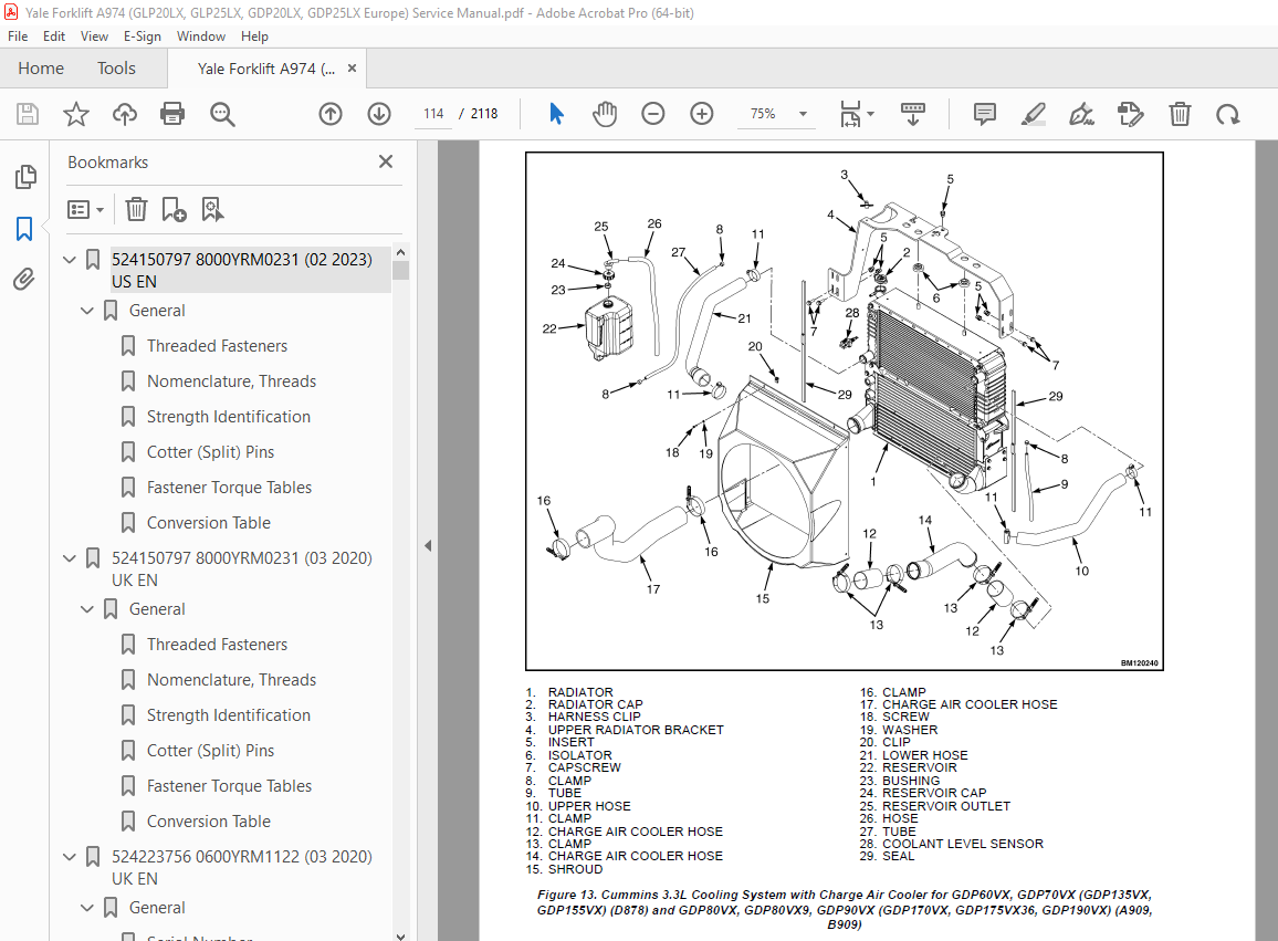
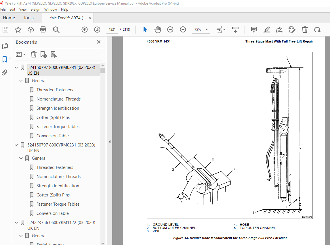
TABLE OF CONTENTS:
Yale Forklift A974 (GLP20LX, GLP25LX, GDP20LX, GDP25LX Europe) Service Manual – PDF DOWNLOAD
524150797 8000YRM0231 (02 2023) US EN 1
General 7
Threaded Fasteners 7
Nomenclature, Threads 7
Strength Identification 8
Cotter (Split) Pins 9
Fastener Torque Tables 14
Conversion Table 16
524150797 8000YRM0231 (03 2020) UK EN 23
General 27
Threaded Fasteners 27
Nomenclature, Threads 27
Strength Identification 28
Cotter (Split) Pins 29
Fastener Torque Tables 34
Conversion Table 36
524223756 0600YRM1122 (03 2020) UK EN 43
General 47
Serial Number 48
Engine Removal and Installation 48
Cylinder Head, Camshaft, and Valve Mechanism Repair 48
Remove 48
Clean 51
Inspect and Repair 51
Cylinder Head 51
Rocker Shaft Assembly 51
Camshaft 52
Valve Guides 53
Valve Seats 53
Valves 54
Valve Springs 54
Install 55
Crankshaft and Main Bearings Repair 59
Remove 59
Inspect and Repair 60
Crankshaft 60
Main Bearings 60
Install 61
Pistons and Connecting Rods Repair 62
Remove and Disassemble 62
Clean 62
Inspect and Repair 62
Pistons 62
Piston Rings 62
Connecting Rods and Bearings 63
Assemble and Install 63
Cylinder Block Repair 65
Oil Pump Repair 66
Remove 66
Disassemble 67
Clean 67
Inspect 67
Assemble 68
Install 68
Cooling System Repair 70
Thermostat 70
Replace 70
Fan Assembly 70
Remove and Disassemble 70
Assemble and Install 71
Water Pump 71
Remove 71
Install 72
Flywheel and Ring Gear Repair 73
Remove 73
Install 73
Valve Adjustment 73
Compression Pressure Check 75
Engine Timing Adjustment 76
Engine Specifications 76
Engine Data 76
Engine Speeds 76
2007, and Later, Emission Compliant Engines 76
All Engines Except 2007, and Later, Emission Compliant Engines 77
Thermostat 77
Cylinder Head 77
Valve Mechanism 77
Camshaft 78
Crankshaft 78
Connecting Rods 78
Cylinder Block 79
Pistons 79
Oil Pump 79
Torque Specifications 80
524223757 0700YRM1123 (06 2016) UK EN 83
General 87
Cooling System Checks 87
Exhaust Leaks Into Cooling System 87
Water Flow Restrictions in Radiator 87
Radiator Hoses 87
Water Pump 88
Flushing the Cooling System 88
Cooling System, Clean 88
Radiator Replacement 89
Radiator, Remove GC/GLC030VX,
GC/GLC035VX, GC/GLC040SVX
(C809); GLP/GDP16VX, GLP/GDP18VX,
GLP/GDP20SVX (GP/GLP/GDP030VX,
GP/GLP/GDP035VX, GP/GLP/GDP040SVX)
(C810); GLC20-35VX (GC/GLC040-070VX,
GC/GLC055SVX) (A910); GLC050LX
(A967); GLP/GDP20-35VX
(GP/GLP/GDP040-070VX) (B875);
GLP/GDP20-25LX (GLP/GDP050LX)
(A974); GLC40, 45, 55VX, GLC55SVX,
(GC/GLC080, 100, 120VX, GC/GLC080,
100VXBCS, GC/GLC120SVX,
GC/GLC120VXPRS) (E818, F818) AND
GLP/GDP40VX5/VX6, GLP/GDP45SVX5,
GLP/GDP45VX6, GLP/GDP50-55VX
(GP/GLP/GDP080, 090, 100, 110, 120VX)
(F813, G813, H813, J813) 90
Radiator, Remove for Lift Trucks Models GC/GLC030VX, GC/GLC035VX,
GC/GLC040SVX (C809); GLP/GDP16VX,
GLP/GDP18VX, GLP/GDP20SVX
(GP/GLP/GDP030VX, GP/GLP/GDP035VX,
GP/GLP/GDP040SVX) (C810); GLC050LX
(A967) AND GLP/GDP20-25LX
(GLP/GDP050LX) (A974) Equipped with Oil Cooler 105
Radiator, Remove for Lift Truck Models GLC/GDC60VX,
GLC/GDC60VX, (GC/GLC/GDC135VX,
GC/GLC/GDC135VX) (C879, D879, E879,
F879) 108
Radiator , Remove for Lift Truck Models GLP/GDP60VX, GLP/GDP70VX
(GP/GLP/GDP135VX, GP/GLP/GDP155VX)
(C878, D878, E878) and GLP/GDP80VX,
GLP/GDP80VX9, GLP/GDP90VX
(GLP/GDP170VX, GLP/GDP175VX36,
GLP/GDP190VX) (A909, B909) 111
Radiator, Install for Lift Truck Models GC/GLC030VX,
GC/GLC035VX, GC/GLC040SVX
(C809); GLP/GDP16VX, GLP/GDP18VX,
GLP/GDP20SVX (GP/GLP/GDP030VX,
GP/GLP/GDP035VX, GP/GLP/GDP040SVX)
(C810); GLC20-35VX (GC/GLC040-070VX,
GC/GLC055SVX) (A910); GLC050LX
(A967); GLP/GDP20-35VX
(GP/GLP/GDP040-070VX) (B875);
GLP/GDP20-25LX (GLP/GDP050LX)
(A974); GLC40, 45, 55VX; GLC55SVX;
(GC/GLC080, 100, 120VX; GC/GLC080,
100VXBCS; GC/GLC120SVX;
GC/GLC120VXPRS) (E818, F818) and
GLP/GDP40VX5/VX6; GLP/GDP45SVX5,
GLP/GDP45VX6, GLP/GDP50-55VX
(GP/GLP/GDP080, 090, 100, 110, 120VX)
(F813, G813, H813, J813) 118
Radiator, Install for Lift Truck Models GC/GLC030VX, GC/GLC035VX,
GC/GLC040SVX (C809); GLP/GDP16VX,
GLP/GDP18VX, GLP/GDP20SVX
(GP/GLP/GDP030VX, GP/GLP/GDP035VX,
GP/GLP/GDP040SVX) (C810); GLC050LX
(A967) and GLP/GDP20-25LX
(GLP/GDP050LX) (A974) Equipped with Oil Cooler 123
Radiator, Install for Lift Truck Models GLC/GDC60VX,
GLC/GDC60VX, (GC/GLC/GDC135VX,
GC/GLC/GDC135VX) (C879, D879, E879,
F879) 125
Radiator, Install for Lift Truck Models GLP/GDP60VX, GLP/GDP70VX (GP/GLP/GDP135VX, GP/GLP/GDP155VX) (C878, D878, E878) and GLP/GDP80VX, GLP/GDP80VX9, GLP/GDP90VX (GLP/GDP170VX, GLP/GDP175VX36, GLP/GDP190VX) (A909, B909) 128
Fan Assembly Replacement 140
Fan Removal 140
Inspect 155
Fan Installation 155
524223765 1800YRM1135 (09 2018) UK EN 161
General 165
Dry Brake System 165
Wet Brake System 165
Service Brakes Repair (Dry Brake) 165
Remove and Disassemble 166
Clean 174
Inspect 174
Assemble and Install 175
Adjust 182
Inching Overlap Adjustment 182
Parking Brake Repair 183
Remove and Disassemble 183
Assemble and Install 186
Adjust 186
Master Cylinder Repair 187
Remove (Dry Brake) 187
Disassemble (Dry Brake) 188
Clean and Inspect (Dry Brake) 190
Assemble (Dry Brake) 190
Bench Bleed Master Cylinder (Dry Brake) 190
Install and Adjust (Dry Brake) 190
Remove (Wet Brake) 191
Disassemble (Wet Brake) 193
Clean and Inspect (Wet Brake) 194
Assemble (Wet Brake) 195
Install and Adjust (Wet Brake) 195
Service Brakes Adjustment (Dry Brake) 196
Brake System Air Removal 196
Using Pressure Bleed System 196
Using Brake Pedal Pressure 197
Brake Pedal Adjustment 197
Free Pedal Adjustment 198
Torque Specifications 200
524223766 1900YRM1136 (11 2017) UK EN 203
General 207
Hydraulic Gear Pump Assembly 208
Variable Displacement Pump Assembly 209
Single Gear Pump Assembly Repair 209
Remove 209
Disassemble 216
Clean 216
Inspect 218
Assemble 218
Install 218
Tandem Gear Pump Assembly 222
Remove 223
Disassemble 225
Clean 227
Inspect 227
Assemble 227
Install 228
Gear Pump Specifications 228
24 0 to 45 0 cc/rev – Variable Displacement Pump Repair 234
Remove 234
Disassemble 244
Clean 247
Inspect 247
Assemble 247
Install 248
63 0 cc/rev – Variable Displacement Pump Repair 251
Remove 251
Disassemble 254
Clean 254
Inspect 254
Assemble 256
Install 256
Variable Displacement Pump Checks and Adjustments (Single Pump) 258
Margin Pressure Check 258
Flow Compensator Adjustment 259
Pressure Compensator Adjustment 259
Variable Displacement Pump Checks and Adjustments (Tandem Pump) 260
Variable Displacement Pump Specifications 263
Torque Specifications 264
Hydraulic Gear Pump 265
Variable Displacement Pump 266
Special Tools 266
524223767 2000YRM1137 (01 2017) UK EN 271
General 277
Electro-Hydraulic Main Control Valve 278
Description 278
Remove 286
Electro-Hydraulic Control Valve Sections 291
General 291
Outlet Control Valve Section 291
Remove 291
Disassemble 292
Clean 294
Inspect 294
Assemble 294
Install 295
Auxiliary Control Valve Sections 295
Remove 295
Disassemble 302
Clean 303
Inspect 304
Assemble 304
Install 306
Tilt Control Valve Section 307
Remove 307
Disassemble 307
Clean 313
Inspect 313
Assemble 313
Install 314
Lift/Lower Control Valve Section 315
Remove 315
Disassemble 315
Clean 324
Inspect 324
Assemble 324
Install 325
Mid-Inlet Section 325
Remove 325
Clean 326
Inspect 326
Install 326
Install 326
Electro Hydraulic Poppet Valve (EHPV) Pilot Pin Adjustment 331
Lift Pilot Pin 331
Lower Pilot Pin 335
Abnormal/Erroneous EHPV Adjustment 337
Manual Main Control Valve 338
Description 338
Remove 342
OPS Solenoid Assembly 350
General 350
Remove 351
Clean and Inspect 354
Install 354
Manual Control Valve Sections 355
General 355
Outlet Control Valve Section 355
Remove 355
Disassemble 355
Clean 358
Inspect 358
Assemble 358
Install 359
Auxiliary Control Valve Sections 359
Remove 359
Disassemble 359
Clean 362
Inspect 362
Assemble 362
Install 363
Lift/Tilt Control Valve Section 363
Remove 363
Disassemble 363
Clean 370
Inspect 370
Assemble 371
Install 372
Mid-Inlet Section 373
Remove 373
Clean 373
Inspect 373
Install 373
Install 374
Pressure Relief Valve Check and Adjustment 380
Primary Relief Valve 381
Secondary Relief Valve 385
Steering Control Unit Repair 392
Steering Control Unit, Remove 392
Steering Control Unit, Disassemble 396
Steering Control Unit, Clean 398
Steering Control Unit, Inspect 398
Steering Control Unit, Assemble 398
Relief Valve, Disassemble 399
Relief Valve, Clean 399
Relief Valve, Inspect 400
Relief Valve, Assemble 400
Steering Control Unit, Install 400
524223768 2100YRM1139 (02 2014) UK EN 405
524223769 2200YRM1128 (01 2023) US EN 453
Series Code / Model Designation Reference Table 461
General 463
Deutsch Crimping Tool 464
How to Strip a Wire for Use With Deutsch Crimping Tool 464
How to Crimp With the Deutsch Crimping Tool 465
Calibration Test for the Deutsch Crimping Tool 467
Deutsch Connectors 469
DT, DTM, and DTP Series Connectors 469
HD Series Connectors 512
Metri-Pack Connectors 534
Remove and Install 534
Micro-Pack Connectors 537
Weather-Pack Connectors 538
AMPSEAL Crimping Tools 540
AMP Hand Crimping Tool With Certi-Crimp 540
Description 540
Stripping Wire for Use with AMP Hand Crimping Tool 541
Insulation Crimp Adjustment 542
Maintenance and Inspection for AMP Hand Crimping Tool 542
AMP Hand Crimping Tool 542
Crimp Height Inspection 542
How to use AMP Hand Crimping Tool 543
AMP Pro-Crimper II Tool 543
Description 543
Remove and Install Die Set and Locator Assembly 544
Stripping Wire for Use With AMP PRO-CRIMPER II Tool 544
Contact Support Adjustment 545
Crimp Height Adjustment 546
Maintenance and Inspection Procedures 546
PRO-CRIMPER II Tool 546
Crimp Height Inspection 546
How to Use AMP PRO-CRIMPER II Tool 547
AMPSEAL Connector Assemblies 548
Description for Plug Connector Assembly 548
Seal Plug 549
Contact Crimping 549
Description for Plug Connector and Header Assembly 554
Voltage Reading 557
Seal Plug 557
Contact Crimping 557
AMP Superseal 1 5 Crimping Tools 564
Mini Mic Receptacle and Tab Contacts 564
Description 564
Crimping Conditions and Measurements 564
Insertion of Rubber Seal on Cable 566
AMP Hand Application Tool 571
Description 571
Maintenance and Inspection 571
Crimp Height Inspection 571
Crimp Height Adjustment 572
How to Use AMP Hand Application Tool 572
AMP Pro-Crimper II Tool 573
Description 573
Remove and Install Die Set and Locator Assembly 573
Adjustments 574
Contact Support 574
Crimp Height 575
Inspections and Maintenance 576
Crimp Height Inspection 576
Visual Inspection 576
Maintenance 577
How to Use Pro-Crimper II Tool 577
AMP Superseal 1 5 Connector Assemblies 578
Description 578
Repair and Maintenance 585
Panel Mount Option 585
AMP Fastin-Faston Hand Tools 586
Description – AMP Double Action Hand Tool 586
Maintenance and Inspection Procedures 586
Daily Maintenance 586
Periodic Tool Inspection 587
Lubrication 587
Visual Inspection 587
Crimp Height Inspection 587
Certi-Crimp Ratchet Inspection 588
How to Use AMP Double Action Hand Tool 589
Description – AMP Extraction Tool 590
Maintenance and Inspection 591
How to Use AMP Extraction Tool 591
AMP Fastin-Faston Receptacles and Housings 593
Description 593
Wire Repair 601
Wire Splicing Requirements 601
Deutsch Jiffy Splice 602
Twisted/Shielded Cable and Leads Repair 608
Special Tools 610
524223769 2200YRM1128 (07 2020) UK EN 619
Series Code / Model Designation Reference Table 625
General 628
Deutsch Crimping Tool 628
How to Strip a Wire for Use With Deutsch Crimping Tool 628
How to Crimp With the Deutsch Crimping Tool 629
Calibration Test for the Deutsch Crimping Tool 631
Deutsch Connectors 633
DT, DTM, and DTP Series Connectors 633
HD Series Connectors 675
Metri-Pack Connectors 698
Remove and Install 698
Micro-Pack Connectors 700
Weather-Pack Connectors 701
AMPSEAL Crimping Tools 703
AMP Hand Crimping Tool With Certi-Crimp 703
Description 703
Stripping Wire for Use with AMP Hand Crimping Tool 703
Insulation Crimp Adjustment 704
Maintenance and Inspection for AMP Hand Crimping Tool 704
AMP Hand Crimping Tool 704
Crimp Height Inspection 704
How to use AMP Hand Crimping Tool 705
AMP Pro-Crimper II Tool 705
Description 705
Remove and Install Die Set and Locator Assembly 706
Stripping Wire for Use With AMP PRO-CRIMPER II Tool 707
Contact Support Adjustment 707
Crimp Height Adjustment 708
Maintenance and Inspection Procedures 708
PRO-CRIMPER II Tool 708
Crimp Height Inspection 708
How to Use AMP PRO-CRIMPER II Tool 709
AMPSEAL Connector Assemblies 710
Description for Plug Connector Assembly 710
Seal Plug 711
Contact Crimping 711
Description for Plug Connector and Header Assembly 716
Voltage Reading 718
Seal Plug 718
Contact Crimping 718
AMP Superseal 1 5 Crimping Tools 725
Mini Mic Receptacle and Tab Contacts 725
Description 725
Crimping Conditions and Measurements 725
Insertion of Rubber Seal on Cable 727
AMP Hand Application Tool 732
Description 732
Maintenance and Inspection 732
Crimp Height Inspection 732
Crimp Height Adjustment 733
How to Use AMP Hand Application Tool 733
AMP Pro-Crimper II Tool 734
Description 734
Remove and Install Die Set and Locator Assembly 735
Adjustments 735
Contact Support 735
Crimp Height 736
Inspections and Maintenance 737
Crimp Height Inspection 737
Visual Inspection 737
Maintenance 738
How to Use Pro-Crimper II Tool 738
AMP Superseal 1 5 Connector Assemblies 739
Description 739
Repair and Maintenance 746
Panel Mount Option 746
AMP Fastin-Faston Hand Tools 747
Description – AMP Double Action Hand Tool 747
Maintenance and Inspection Procedures 747
Daily Maintenance 747
Periodic Tool Inspection 748
Lubrication 748
Visual Inspection 748
Crimp Height Inspection 748
Certi-Crimp Ratchet Inspection 749
How to Use AMP Double Action Hand Tool 750
Description – AMP Extraction Tool 751
Maintenance and Inspection 751
How to Use AMP Extraction Tool 752
AMP Fastin-Faston Receptacles and Housings 753
Description 753
Wire Repair 760
Wire Splicing Requirements 760
Deutsch Jiffy Splice 761
Twisted/Shielded Cable and Leads Repair 766
Special Tools 769
524240453 0600YRM1205 (01 2017) UK EN 777
General 783
Engine Identification 783
Major Engine Component Identification 783
Location of Labels 784
Engine Removal and Installation 785
Cylinder Head Assembly Repair 785
Glow Plugs 788
Remove 788
Install 788
Valve Cover 788
Remove 788
Clean and Inspect 789
Install 789
Rocker Arm Assembly 789
Remove 789
Disassemble 790
Clean and Inspect 791
Push Rods 791
Rocker Arm Assembly 791
Assemble 791
Install 792
Valve Clearance Adjustments 792
Cylinder Head Assembly 793
Remove 793
Disassemble 798
Valves and Valve Springs, Remove 798
Valve Guides, Remove 798
Clean and Inspect 799
Cylinder Head 799
Valve Guides 800
Valves 800
Valve Sink 800
Valve Seat 801
Valve Springs 801
Assemble 802
Valve Guides, Install 802
Valves and Valve Springs, Install 802
Install 803
Timing Gear Case and Timing Gears Repair 804
Timing Gear Case Cover 805
Remove 805
Clean and Inspect 805
Install 806
Timing Gears 806
Crankshaft Gear 807
Remove 807
Install 807
Idler Gear 807
Remove 807
Inspect 808
Install 808
Camshaft Gear 808
Remove 808
Install 809
Timing Gear Case 809
Remove 809
Clean and Inspect 810
Install 810
Drive Train, Camshaft, and Cylinder Block Repair 811
Remove 811
Disassemble 812
Pistons and Connecting Rods 812
Crankshaft 812
Camshaft 815
Clean and Inspect 816
Cylinder Block 816
Honing and Boring 819
Pistons 820
Piston Pin 820
Connecting Rod 821
Tappets 821
Crankshaft 822
Camshaft 823
Camshaft Bushing 824
Assemble 824
Camshaft 824
Crankshaft 824
Pistons and Connecting Rods 825
Install 826
Lubrication System Repair 827
Engine Oil and Oil Filter Change 827
Oil Pan 827
Remove 827
Install 828
Oil Suction Tube 828
Remove 828
Clean 829
Install 829
Oil Pump 829
Remove 829
Clean and Inspect 830
Outer Rotor Outside Clearance 830
Outer Rotor to Inner Rotor Tip Clearance 831
Outer Rotor Side Clearance 831
Rotor Shaft Clearance 831
Install 832
Fuel System Repair 832
Fuel Injectors 833
Remove 833
Inspect 834
Clean 834
Test 834
Install 837
Electronic Throttle System 837
Remove 837
Install 840
Inspect 841
Adjust 842
Manual Throttle System 843
Fuel Injection Pump 843
Remove 843
Clean and Inspect 847
Install 847
Check/Adjust Fuel Injection Timing 848
Cooling System Repair 850
V-Belt 850
Remove 850
Inspect 850
Install 850
Adjust 850
Water Pump 852
4TNE92-NMHA, 4TNE92-NMHA/580090035, 4TNE92-SNMU, and 4TNE98-SNMU Engines 852
Remove 852
Install 853
4TNE92-NMH, 4TNE98-NMH, 4TNE92-NMH/580090036, and 4TNE98-BNMH Engines 854
Remove 854
Install 855
Thermostat 857
Remove 857
Inspect 858
Install 858
Flywheel and Flywheel Housing 858
Flywheel 859
Remove 859
Install 860
Flywheel Housing 860
Remove 860
Install 860
Electrical Equipment Repair 862
Alternator 862
Remove 862
Bench Test 864
Regulate Voltage Check 864
No Load Test 866
Output Test 866
Install 866
Starter 867
Remove 868
No Load Test 868
Install 869
Engine Specifications 870
Engine Data 870
Engine Tuning 878
Cylinder Head 878
Intake/Exhaust Valve and Guide 879
Valve Spring 879
Rocker Arm and Shaft 879
Push Rod 880
Gear Train and Camshaft 880
Camshaft 880
Idle Gear Shaft and Bushing 880
Backlash of Each Gear 881
Cylinder Block 881
Crankshaft 881
Thrust Bearing 882
Piston 882
Piston Ring 882
Connecting Rod 883
Rod Small End 883
Tappet 883
Oil Pump 884
Engine Oil Pressure 884
Outer Rotor Outside Clearance 884
Outer Rotor Side Clearance 884
Outer Rotor to Inner Rotor Tip Clearance 884
Rotor Shaft Clearance 884
Standard Torque Specifications 885
Standard Torque Chart 885
Special Torque Specifications 886
Special Tools 887
524289374 0900YRM1326 (04 2018) UK EN 895
General 901
LPG Tank and Bracket Replacement 901
Remove LPG Tank for Lift Truck Models GLC030VX, GLC035VX, GLC040SVX (C809), GLP/GDP16VX, GLP/GDP18VX, GLP/GDP20SVX (GP/GLP/GDP030VX, GP/GLP/GDP035VX, GP/GLP/GDP040SVX) (C810), GLC20-35VX (GLC040-070VX, GLC055SVX) (A910), and GLP/GDP20-35VX (GP/GLP/GDP040-070VX) (B875) 901
Install LPG Tank for Lift Truck Models GLC030VX, GLC035VX, GLC040SVX (C809), GLP/GDP16VX, GLP/GDP18VX, GLP/GDP20SVX (GP/GLP/GDP030VX, GP/GLP/GDP035VX, GP/GLP/GDP040SVX) (C810), GLC20-35VX (GLC040-070VX, GLC055SVX) (A910), and GLP/GDP20-35VX (GP/GLP/GDP040-070VX) (B875) 903
Remove LPG Tank for Lift Truck Models GLC050LX (A967) and GLP20-25LX (GLP050LX) (A974) 904
LPG Tank Install for Lift Truck Models GLC050LX (A967) and GLP20-25LX (GLP050LX) (A974) 906
Remove LPG Bracket for Lift Truck Models GLC030VX, GLC035VX, GLC040SVX (C809), GLP/GDP16VX, GLP/GDP18VX, GLP/GDP20SVX (GP/GLP/GDP030VX, GP/GLP/GDP035VX, GP/GLP/GDP040SVX) (C810), GLC20-35VX (GLC040-070VX, GLC055SVX) (A910), and GLP/GDP20-35VX (GP/GLP/GDP040-070VX) (B875) 907
Install LPG Bracket for Lift Truck Models GLC030VX, GLC035VX, GLC040SVX (C809), GLP/GDP16VX, GLP/GDP18VX, GLP/GDP20SVX (GP/GLP/GDP030VX, GP/GLP/GDP035VX, GP/GLP/GDP040SVX) (C810), GLC20-35VX (GLC040-070VX, GLC055SVX) (A910), and GLP/GDP20-35VX (GP/GLP/GDP040-070VX) (B875) 909
Remove LPG Tank Bracket Alignment Pin, Lift Truck Models GLC030VX, GLC035VX, GLC040SVX (C809), GLP/GDP16VX, GLP/GDP18VX, GLP/GDP20SVX (GP/GLP/GDP030VX, GP/GLP/GDP035VX, GP/GLP/GDP040SVX) (C810), GLC20-35VX (GLC040-070VX, GLC055SVX) (A910), and GLP/GDP20-35VX (GP/GLP/GDP040-070VX) (B875) 910
Install LPG Tank Bracket Alignment Pin, Lift Truck Models GLC030VX, GLC035VX, GLC040SVX (C809), GLP/GDP16VX, GLP/GDP18VX, GLP/GDP20SVX (GP/GLP/GDP030VX, GP/GLP/GDP035VX, GP/GLP/GDP040SVX) (C810), GLC20-35VX (GLC040-070VX, GLC055SVX) (A910), and GLP/GDP20-35VX (GP/GLP/GDP040-070VX) (B875) 912
Remove LPG Bracket for Lift Truck Models and GLC050LX (A967) and GLP20-25LX (GLP050LX) (A974) 913
Install LPG Bracket for Lift Truck Models GLC050LX (A967) and GLP20-25LX (GLP050LX) (A974) 913
Fuel Filter Unit Repair 913
Fuel Filter Element 913
Remove 913
Clean/Inspect 914
Install 914
Fuel Filter Housing 914
Remove 914
Disassemble 917
Assemble 919
Install 920
Electronic Throttle Body Repair 920
Remove 920
Install 922
Electronic Pressure Regulator (EPR) Repair 922
Remove 923
Disassemble 927
Assemble 929
Install 930
LPG Shutoff Valve Assembly 930
Remove 930
Install 934
Fuel Mixer Repair 936
Remove 936
Install 939
Control System 939
Engine Control Unit (ECU) 939
Remove 939
Install 941
Low LPG Pressure Switch 941
Remove 941
Install 942
LPG Low Level Sensor 942
Remove 943
Install 946
Exhaust System 947
Counterweight Exhaust System 947
Remove and Disassemble 947
Inspect 949
Assemble and Install 949
Overhead Exhaust System 949
Remove and Disassemble 950
Inspect 952
Assemble and Install 952
Exhaust Manifold 953
Remove 953
Install 954
Positive Crankcase Ventilation (PCV) Valve 955
Remove 955
Inspect 955
Install 955
Oxygen Sensor 955
Remove 955
Install 957
LPG Fuel Testing 958
General 958
Available Fuel Tests 958
Composition Test (ASTM D-2163) 958
Ammonia Test (ASTM D-4490) 958
Basic Nitrogen Test (ASTM UOP269-90) 958
Residues Test (ASTM D-2158) 958
Vapor Pressure Test (ASTM D-2598) 958
Sulfur Compounds Test (ASTM D-5623) 959
Methanol Test (ASTM D-4864) 959
Copper Corrosion (ASTM D-1838) 959
Where To Send LPG Fuel Samples For Testing 959
524289375 2200YRM1327 (09 2012) UK EN 963
General 967
Ignition System 967
General 967
Ignition Timing Adjustment, Gasoline and LPG 967
Spark Plugs Check 972
Spark Plug Wires Check 972
Coil Replacement 973
Remove 973
Inspect 974
Install 974
Starter Repair 975
General 975
Remove 975
No-Load Test 976
Magnetic Switch Test 977
Pull-Out Test 977
Holding Coil Test 977
Return Test 977
Pinion Movement Inspection 978
Install 978
Alternator Repair 978
General 978
Charging System Inspection 980
Output Current Check 980
No-Load Adjusted Voltage Check 981
Remove 982
Inspect 982
Rectifier Check 982
Install 983
Engine Sensors and Switches 984
Oil Pressure Sensor, Gas and LPG Engines 984
Remove 984
Install 984
Air Filter Restriction Switch, Gas and LPG Engines 984
Remove 984
Install 984
Cam Angle Sensor, Gas and LPG Engines 985
Remove 985
Install 986
Voltage Check 986
Manifold Absolute Pressure (MAP) Sensor, Gas and LPG Engines 987
Remove 987
Install 988
Intake Air Temperature (IAT) Sensor, LPG Engines 989
Remove 989
Install 989
Intake Air Temperature (IAT) Sensor, Gas Engines 989
Remove 989
Install 989
Fuel Temperature Sensor, LPG Engines 992
Remove 992
Install 992
Engine Coolant Temperature (ECT) Sensor 993
2007 Emissions Compliant Gas Engines 993
Remove 993
Install 993
2007 and 2010 Emissions Compliant LPG Engines 994
Remove 994
Install 994
2010 Emissions Compliant Gas and LPG Engines 996
Remove 996
Install 996
550013974 0100YRM1423 (03 2012) UK EN 1001
toc 1001
Frame 1001
Safety Precautions Maintenance and Repair 1002
General 1005
Hood, Seat, and Side Covers Replacement 1006
Remove 1006
Install 1012
Belly Pan (Optional) 1013
Remove 1013
Clean and Inspect 1013
Install 1013
Steering Column 1014
Description 1014
Steering Column Repair 1014
Remove 1014
Disassemble 1015
Clean 1018
Inspect 1018
Assemble 1018
Install 1018
Counterweight Replacement 1019
Remove 1019
Install 1021
Overhead Guard Replacement 1021
Remove 1021
Install 1022
Rain Top (Optional) 1022
Remove 1022
Clean and Inspect 1022
Install 1022
Operator Restraint System Replacement 1023
Description 1023
Emergency Locking Retractor (ELR) 1023
Engine Replacement 1025
Remove 1025
LPG Engine 1025
Diesel Engine 1033
Install 1038
LPG Engine 1038
Diesel Engine 1039
Transmission Replacement 1040
Remove 1040
Install 1042
Throttle Pedal and Cable Adjustment 1043
Mazda LPG Engine 1043
Throttle Pedal Stop Adjustment 1043
Yanmar Diesel Engine 1043
Yanmar Diesel Engine With Electronic Throttle 1045
Cooling System 1045
Description 1045
Hydraulic Filter Repair 1045
Remove 1045
Clean and Inspect 1046
Install 1046
Tank Repair 1046
LPG Tank Repair 1046
Hydraulic and Diesel Tanks 1046
Inspect 1046
Clean 1047
Steam Method of Cleaning 1047
Chemical Solution Method of Cleaning 1048
Additional Preparations for Repair 1048
Small Leaks, Repair 1048
Large Leaks, Repair 1048
Preparations for Use After Repair 1049
Label Replacement 1049
tables 1001
Table 1 Weight of Counterweights 1020
550013975 1400YRM1426 (07 2011) UK EN 1057
toc 1057
Drive Axle and Differential Assembly Repair 1057
Safety Precautions Maintenance and Repair 1058
General 1061
Identification Plate 1061
Drive Axle Repair 1062
Remove and Disassemble 1062
Clean and Inspect 1065
Assemble and Install 1065
Differential Repair 1068
Remove 1068
Differential Assembly From Drive Axle Center Section Assembly 1068
Drive Pinion, Pinion Gear, and Bearings From Drive Axle Center S 1070
Disassemble 1075
Differential Assembly 1075
Drop Box Housing 1079
Differential Assembly Cover 1080
Drive Axle Center Section 1081
Clean and Inspect 1082
Assemble 1083
Drive Axle Center Section 1083
Differential Assembly Cover 1085
Drop Box Housing 1086
Differential Assembly 1087
Install 1091
Pinion Inner Shim Set, Adjust Thickness (Depth of Pinion) 1091
Drive Pinion, Pinion Gear, and Bearings Into Drive Axle Center S 1093
Differential Assembly Into Drive Axle Center Section 1097
Hypoid Gear Backlash, Adjust 1100
Hypoid Gear, Runout Check 1101
Gear Set, Tooth Contact Pattern Check 1101
Torque Specifications 1104
tables 1057
Table 1 Pinion Variation Numbers Examples 1092
Table 2 Ring and Pinion Tooth Contact Adjustment 1102
Table 3 Correct Tooth Contact 1102
Table 4 Incorrect Tooth Contact 1103
550013976 1600YRM1425 (07 2011) UK EN 1107
toc 1107
Steering Axle 1107
Safety Precautions Maintenance and Repair 1108
General 1111
Steering Axle Assembly Repair 1112
Remove 1112
Disassemble 1112
Clean 1114
Inspect 1114
Assemble 1115
Install 1116
Spindles, Bearings, and Tie Rods Repair 1118
Spindles and Bearings 1118
Remove 1118
Disassemble 1118
Clean 1119
Inspect 1119
Assemble 1119
Install 1120
Tie Rods 1120
Remove 1120
Disassemble 1121
Clean 1121
Inspect 1121
Assemble 1121
Install 1122
Steering Cylinder Repair 1122
Remove 1122
Disassemble 1122
Clean 1123
Inspect 1124
Assemble 1124
Install 1124
Torque Specifications 1124
550013977 2200YRM1427 (03 2012) UK EN 1127
toc 1127
Electrical System 1127
Safety Precautions Maintenance and Repair 1128
General 1131
Engine Control Module (ECM), Yanmar Diesel Engine 1132
Remove 1132
Install 1132
Display Switch Cluster 1133
Remove 1133
Install 1134
Direction Control Lever 1135
Remove 1135
Install 1135
Key Switch 1136
Remove 1136
Install 1136
Display Switch Cluster Panel Bezel and Overlay 1137
Remove 1137
Install 1137
Steering Column Repair 1137
Remove 1137
Disassemble 1137
Assemble 1138
Install 1138
Sensors and Switches 1139
General 1139
Dash Panel, Kick Panel, and Seal Plate, Remove and Install 1139
Remove 1139
Install 1139
Accelerator Pedal Position Sensor 1140
Remove 1140
Install 1141
Brake Fluid Level Switch 1142
Remove 1142
Install 1143
Brake Pedal Position Sensor 1143
Remove 1143
Install 1143
Parking Brake Position Sensor 1144
Remove 1144
Install 1145
Seat Sensor (Operator Presence System) 1145
Non-Suspension Seat 1145
Remove 1145
Install 1146
Full Suspension Seats 1146
Remove 1146
Install 1146
Transmission Pressure Sensors (Transducers) 1147
Remove 1147
Install 1147
Transmission Temperature Sensor 1147
Remove 1147
Install 1148
Rear Horn Button Switch 1148
Remove 1148
Install 1148
Engine and Fuel Sensors and Switches, Mazda 2 0L LPG Trucks 1149
Engine and Fuel Sensors, Yanmar 2 6L Diesel Trucks 1149
Engine Speed Sensor 1149
Remove 1149
Install 1149
Oil Pressure Sensor 1149
Remove 1149
Install 1150
Engine Coolant Temperature (ECT) Sensor 1150
Remove 1150
Install 1150
Fuel/Water Separator Sensor 1151
Remove 1151
Install 1151
Glow Plug Relay 1152
Remove 1152
Install 1152
Power Distribution Module (PDM) and Component Parts 1154
Power Distribution Module (PDM) as a Unit 1154
Remove 1154
Install 1154
Power Distribution Module (PDM) Components 1156
Remove and Install 1156
Battery 1156
Remove 1156
Install 1156
Lights 1157
Work Lights (Front and Rear) 1157
Remove 1157
Install 1157
Strobe Light 1157
Remove 1157
Install 1157
LED Tail, Backup, and Brake Lights 1158
Remove 1158
Install 1158
Reflectors 1158
Remove 1158
Install 1158
550013978 4000YRM1431 (02 2014) UK EN 1163
550013980 8000YRM1428 (10 2015) UK EN 1231
Lift Truck Lifting Capacity 1235
Counterweight Weights 1235
Tire Sizes 1235
Capacities 1236
Electrical System 1237
Transmission Oil Pressures 1238
Hydraulic System Relief Pressures 1240
Steering System 1240
Stall Speeds 1240
Mast Speeds 1241
Tilt Angles 1242
Front End Equipment 1242
Mast Creep 1242
Engine Specifications 1243
Torque Specifications 1244
Frame 1244
Mast 1244
Steering System 1244
Drive Axle 1244
Transmission 1245
Engine – Mazda FE and F2 LPG 1245
550013981 8000YRM1429 (09 2017) UK EN 1249
Diagrams and Schematics 1253
550022929 9000YRM1434 (02 2018) UK EN 1275
SECTION 9010 Operational Diagnostic Procedures 1281
Group 05 – Operational Checkout 1283
SECTION 9020 Engine 1293
Group 10 – Principles of Operation 1297
Group 30 – Observed Symptoms 1353
Group 40 – Tests and Adjustments 1407
SECTION 9030 Electrical System 1419
Group 03 – General Maintenance and Diagnostic Data 1425
Group 10 – Principles of Operation 1447
Group 20 – Diagnostic Trouble Codes 1457
Group 30 – Observed Symptoms 1643
SECTION 9040 Drive Train 1679
Group 10 – Principles of Operation 1681
Group 30 – Observed Symptoms 1695
Group 40 – Tests and Adjustments 1725
SECTION 9050 Hydraulic Systems 1729
Group 10 – Principles of Operation 1731
Group 33 – Observed Symptoms-Gear Pump 1747
Group 43 – Tests and Adjustments-Gear Pump 1781
SECTION 9060 Operators Station 1797
Group 10 – Principles of Operation 1799
SECTION 9070 Front End (Mast) and Chassis 1809
Group 10 – Principles of Operation 1811
Group 30 – Observed Symptoms 1821
SECTION 9080 Supplementary Data 1863
Group 50 – Abbreviations and Acronyms 1865
Group 60 – Special Tools List 1873
Group 70 – Fault Mode Indicator Reference 1875
Group 80 – Supplier Specification Data 1877
550030170 1300YRM1447 (08 2013) UK EN 1881
toc 1881
Single Speed Powershift 1881
Safety Precautions Maintenance and Repair 1882
General 1885
Serial Number 1885
Hydraulic Gear Pump 1886
Remove 1886
Install 1886
Housing Fittings Replacement 1886
Remove 1886
Disassemble 1887
Assemble 1887
Install 1887
Charge Pump Repair 1887
Lift Trucks Manufactured Before July, 2013 1887
Remove 1887
Disassemble 1889
Clean 1889
Inspect 1889
Assemble 1889
Install 1889
Lift Trucks Manufactured After July, 2013 1891
Remove 1891
Clean 1891
Inspect 1891
Install 1892
Torque Converter Replacement 1895
Remove 1895
Clean and Inspect 1895
Install 1895
Stator Support Assembly Repair 1897
Remove 1897
Disassemble 1902
Clean 1906
Inspect 1906
Assemble 1907
Install 1907
Clutch Packs Repair 1910
Remove 1910
Disassemble 1911
Housings 1911
Clutch Packs 1916
Forward Clutch Pack 1916
Reverse Clutch Pack 1921
Clean 1927
Inspect 1927
Assemble 1928
Clutch Packs 1928
Reverse Clutch Pack 1928
Forward Clutch Pack 1935
Housings 1942
Install 1942
Drive Chains and Sprockets 1948
Remove 1948
Clean 1950
Inspect 1950
Install 1950
Proportional and Enable Solenoid Valves 1951
Proportional Valves 1951
Remove 1951
Disassemble 1951
Clean and Inspect 1951
Assemble 1954
Install 1954
Enable Solenoid Valve 1954
Remove 1954
Disassemble 1955
Clean and Inspect 1955
Assemble 1955
Install 1955
Foot Directional Control Pedal Repair 1957
Remove and Disassemble 1957
Clean and Inspect 1961
Assemble and Install 1961
550038077 8000YRM1424 (08 2013) UK EN 1967
toc 1967
Periodic Maintenance 1967
Safety Precautions Maintenance and Repair 1968
General 1973
Serial Number Data 1973
How to Move Disabled Lift Truck 1973
How to Tow Lift Truck 1973
How to Put Lift Truck on Blocks 1974
How to Raise Drive Tires 1974
How to Raise Steering Tires 1975
How to Clean a Lift Truck 1975
Maintenance Schedule 1976
Maintenance Procedures Every 8 Hours or Daily 1984
How to Make Checks With Engine Stopped 1984
Tires and Wheels 1984
Safety Labels 1984
Mast, Carriage, Lift Chains, Header Hoses, Attachment 1984
Operator Restraint System 1987
Emergency Locking Retractor (ELR) 1987
Adjust Seat – Full Suspension 1990
Adjust Seat – Internal Suspension 1990
Hood and Seat Latches 1990
Engine Compartment 1990
Ground Static Strap 1990
Fuel, Oil, and Coolant Leaks, Check 1991
Hydraulic Hoses 1991
Coolant Hoses 1991
Steering Column Gas Cylinder 1991
Transmission 1992
Hydraulic System Oil 1992
Engine Oil 1993
Air Filter 1993
Forks 1996
Remove 1996
Inspect 1996
Install 1996
Adjust 1998
How To Make Checks With Engine Running 1998
Indicator Lights, Horn, Fuses, and Relays 1998
Service Brakes 2001
Brake Fluid Level 2001
Operation, Check 2001
Parking Brake 2001
Engine Oil Pressure 2001
Cooling System 2001
Steering System 2002
Control Levers and Pedals 2002
Lift System, Operate 2002
First Service After First 100 Hours of Operation 2004
Mazda Engine Oil and Oil Filter Change 2004
Yanmar Engine Oil and Oil Filter Change 2004
Hydraulic System 2004
Hydraulic Filter Element, Replace 2004
Remove 2004
Install 2006
Maintenance Procedures Every 500 Hours or 1 Year 2008
Hydraulic System Oil 2008
Hydraulic Tank Breather 2008
Inspect 2008
Mazda Engine Oil and Oil Filter Change 2010
Mazda Drive Belt Check 2010
Fan and Alternator Drive Belt 2010
Drain Tar From Electronic Pressure Regulator (EPR) 2010
Yanmar Engine Oil and Oil Filter Change 2011
Drive Belt 2011
Yanmar Diesel Engine 2011
Fan and Alternator Drive Belt 2011
Battery 2014
PCV Valve 2014
Clean Debris From Radiator Core 2014
Transmission Oil Level 2015
Forks 2015
Mast Lubrication 2016
Header Hose Checks 2019
Lift Chain Lubrication 2019
Tilt Cylinder Lubrication 2020
Master Cylinder Rod End Pin Lubrication 2020
Manual Hydraulic Levers Lubrication 2020
Brake Fluid 2020
Parking Brake Adjustment 2020
Tie Rod Lubrication 2022
Differential and Drive Axle Oil 2022
Maintenance Procedures Every 1000 Hours or 1 Year 2024
Valve Clearance, Check and Adjust 2024
Ignition System, Mazda Engine 2024
LPG Fuel Filter Replace, Mazda Engine 2024
Remove 2024
Clean/Inspect 2026
Install 2026
Fuel Filter Replacement, Yanmar Engine 2026
Priming the Fuel System (Yanmar) 2027
Lift Chains Wear Check 2028
Lift Chain Lubrication 2028
Integral Sideshift Carriage, Check Bearings 2028
Steering Axle 2028
Control Levers and Pedals 2028
Maintenance Procedures Every 2000 Hours or Annually 2030
Hydraulic System 2030
Hydraulic Oil Filter Element, Replace 2030
Remove 2030
Clean and Inspect 2030
Install 2030
Hydraulic Tank Breather, Replace 2032
Air Filter 2032
PCV Valve 2035
Oxygen Sensor 2035
Timing Belt, Mazda Engine 2036
Fuel Injector, Yanmar Engine 2036
Forks 2036
Integral Sideshift Carriage 2036
Bearings, Replace 2036
Transmission Oil and Oil Filter, Replace 2036
Remove 2036
Clean and Inspect 2036
Install 2037
Brake Fluid Change 2037
Service Brakes 2039
Drive Axle and Differential Oil, Change 2039
Wheel Bearings 2039
Steer Wheels, Lubrication 2039
Maintenance Procedures Every 4000 Hours or 2 Years 2042
Hydraulic Oil, Change 2042
Cooling System 2044
Safety Procedures When Working Near Mast 2046
Hood Latch Check 2048
Lift Chain Adjustments 2049
Jump-Starting the Lift Truck 2050
Jump-Starting Using a Battery Charger 2050
Jump-Starting a Lift Truck Using Another Lift Truck 2050
Welding Repairs 2051
Overhead Guard Changes 2051
Wheels and Tires Replacement 2052
General 2052
Pneumatic Tire With Tube, Repair 2052
Remove Wheels From Lift Truck 2052
Remove Tire From Wheel 2052
Remove Tire From Two-Piece Wheel 2053
Remove Tire From Three- and Four-Piece Wheels 2054
Install Wheel in Tire 2055
Install Two-Piece Wheel in Tire 2056
Install Three- or Four-Piece Wheel in Tire 2057
Add Air to Pneumatic Tires With Tube 2058
Wheels, Install 2058
Pneumatic Tubeless Tire, Repair 2059
Remove Wheels From Lift Truck 2059
Remove Tire From Wheel 2059
Install Tire on Wheel 2061
Add Air to Pneumatic Tubeless Tire 2065
Wheels, Install 2065
Solid Rubber Tires on Pneumatic Wheels, Change 2065
Remove Tire From Wheel 2066
Install Tire on Wheel 2067
Adhesives and Sealants 2069
tables 1967
Table 1 Maintenance Schedule 1979
Table 2 V-Belt Deflection Table 2013
Table 3 Carriage Chain Adjustment, Forks Not Installed 2050
550073240 1900YRM1620 (01 2023) US EN 2073
Proper Flushing after Major Hydraulic Repairs 2079
Introduction 2079
The Phases of Wear 2079
Causes of Hydraulic System Failure 2079
Progression of Contaminant Caused Hydraulic System Failure 2080
Hydraulic System Flushing Techniques 2080
Double Oil and Filter Change 2080
Mechanical Cleaning 2081
Cleaning of Components 2081
How to Clean Tubes and Hoses 2081
Filter Caddy 2081
Start-Up Procedure for Cleaned System 2082
Contaminated Oil Coolers 2082
Additional Filter Caddy Functions 2083
How to Handle Different Fluids 2083
Water Removal Filters 2083
Fluid Conditioning and System Flushing Procedures 2084
Operation of the Filter Caddy 2084
Filter Caddy operation 2084
Fluid Conditioning Procedure 2084
Filter Caddy Start-Up 2085
System Flushing Procedure 2085
Component Cleaning Procedure 2086
Reservoir Cleaning Procedure 2086
Cylinder Cleaning Procedure 2086
Hose and Tube Cleaning Procedure 2086
Valve Cleaning Procedure 2087
Front-End Attachment Cleaning Procedure 2088
System Flushing Procedure 2088
Filter Caddy Start-Up 2089
System Start-Up and Flushing 2089
Reservoir Fluid Cleaning Times 2090
Dealing With Different Fluid Types 2091
Cleaning Procedure After Switching Fluids (Cross Contamination Flushing) 2091
Filter Caddy Maintenance 2091
Servicing the Strainer 2091
DC Motor 2091
Hydraulic Oil Sampling Method and Procedure 2092
Hydraulic Oil Sampling Method 2092
Objective 2092
General Guidelines 2092
Synopsis 2093
Hydraulic Oil Analysis Report Guidelines 2094
Sampling Conditions 2094
Equipment 2094
Sampling Procedure 2095
Hydraulic Oil Sampling 2095
Sample Labeling 2095
Results Documentation 2095
550073240 1900YRM1620 (03 2020) UK EN 2097
Proper Flushing after Major Hydraulic Repairs 2101
Introduction 2101
The Phases of Wear 2101
Causes of Hydraulic System Failure 2101
Progression of Contaminant Caused Hydraulic System Failure 2102
Hydraulic System Flushing Techniques 2102
Double Oil and Filter Change 2102
Mechanical Cleaning 2103
Cleaning of Components 2103
How to Clean Tubes and Hoses 2103
Filter Caddy 2103
Start-Up Procedure for Cleaned System 2104
Contaminated Oil Coolers 2104
Additional Filter Caddy Functions 2104
How to Handle Different Fluids 2104
Water Removal Filters 2105
Fluid Conditioning and System Flushing Procedures 2105
Operation of the Filter Caddy 2105
Filter Caddy operation 2105
Fluid Conditioning Procedure 2106
Filter Caddy Start-Up 2106
System Flushing Procedure 2107
Component Cleaning Procedure 2107
Reservoir Cleaning Procedure 2107
Cylinder Cleaning Procedure 2107
Hose and Tube Cleaning Procedure 2108
Valve Cleaning Procedure 2108
Front-End Attachment Cleaning Procedure 2109
System Flushing Procedure 2109
Filter Caddy Start-Up 2110
System Start-Up and Flushing 2110
Reservoir Fluid Cleaning Times 2111
Dealing With Different Fluid Types 2111
Cleaning Procedure After Switching Fluids (Cross Contamination Flushing) 2111
Filter Caddy Maintenance 2112
Servicing the Strainer 2112
DC Motor 2112
Hydraulic Oil Sampling Method and Procedure 2112
Hydraulic Oil Sampling Method 2112
Objective 2112
General Guidelines 2112
Synopsis 2113
Hydraulic Oil Analysis Report Guidelines 2114
Sampling Conditions 2115
Equipment 2115
Sampling Procedure 2115
Hydraulic Oil Sampling 2115
Sample Labeling 2116
Results Documentation 2116
More products