$45.95
Yale Forklift B216 (ERP20-30ALF) Service Manual – PDF DOWNLOAD
Yale Forklift B216 (ERP20-30ALF) Service Manual – PDF DOWNLOAD
FILE DETAILS:
Yale Forklift B216 (ERP20-30ALF) Service Manual – PDF DOWNLOAD
Language : English
Pages : 1484
Downloadable : Yes
File Type : PDF
IMAGES PREVIEW OF THE MANUAL:
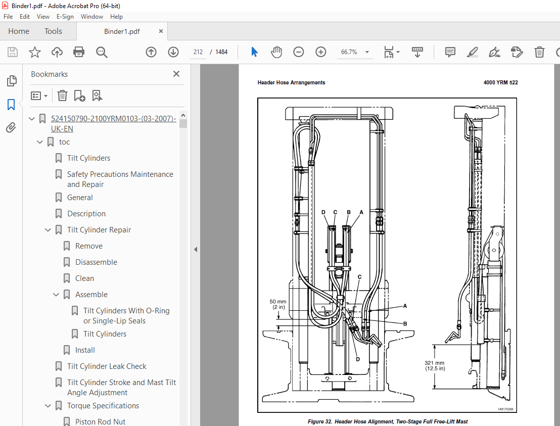
TABLE OF CONTENTS:
Yale Forklift B216 (ERP20-30ALF) Service Manual – PDF DOWNLOAD
524150790-2100YRM0103-(03-2007)-UK-EN 1
toc 1
Tilt Cylinders 1
Safety Precautions Maintenance and Repair 2
General 5
Description 5
Tilt Cylinder Repair 5
Remove 5
Disassemble 5
Clean 5
Assemble 6
Tilt Cylinders With O-Ring or Single-Lip Seals 6
Tilt Cylinders 7
Install 8
Tilt Cylinder Leak Check 10
Tilt Cylinder Stroke and Mast Tilt Angle Adjustment 11
Torque Specifications 11
Piston Rod Nut 11
Retainer 11
Troubleshooting 12
tables 1
Table 1 Movement Rates (Maximum) for Tilt Cylinders 10
524150797-8000YRM0231-(03-2020)-UK-EN 17
General 21
Threaded Fasteners 21
Nomenclature, Threads 21
Strength Identification 22
Cotter (Split) Pins 23
Fastener Torque Tables 28
Conversion Table 30
524158040-2240YRM0001-(03-2020)-UK-EN 37
General 41
Battery Type 41
Lead-Acid Batteries 41
Lithium-Ion Batteries 42
Specific Gravity 42
Chemical Reaction in a Cell 42
Electrical Terms 44
Battery Selection 44
Battery Voltage 45
Battery as a Counterweight 46
Battery Ratings 46
Kilowatt-Hours 46
Battery Maintenance 46
Safety Procedures 46
Maintenance Records 47
New Battery 47
Cleaning Battery 47
Adding Water to Battery 49
Hydrometer 50
Battery Temperature 51
Charging Battery 52
Types of Battery Charges 52
Methods of Charging 54
Troubleshooting Charger 54
Knowing When Battery Is Fully Charged 55
Where to Charge Batteries 55
Equipment Needed 55
Battery Connectors 56
Battery Care 56
Troubleshooting 58
524158752-1600YRM0316-(08-2006)-UK-EN 63
toc 63
Steering Axle 63
Safety Precautions Maintenance and Repair 64
General 67
Description 67
Steering Axle Assembly Repair 68
Remove 68
Install 68
Wheels and Hubs Repair 69
Remove and Disassemble 69
Clean 69
Assemble and Install 69
Spindles, Bearings, and Tie Rods Repair 71
Remove 71
Install 71
Steering Cylinder Repair 72
Remove and Disassemble 72
Clean and Inspect 73
Assemble and Install 73
Torque Specifications 73
Troubleshooting 74
524158753-1600YRM0720-(11-2006)-UK-EN 79
toc 79
Steering Housing and Control Unit 79
Safety Precautions Maintenance and Repair 80
General 83
Description 83
Operation 84
Steering Wheel and Column Assembly Repair 85
Assembly Components, Remove 85
Steering Control Unit, Disassemble 90
Steering Control Unit, Clean 90
Steering Control Unit, Assemble 90
Assembly Components, Install 92
System Air Removal 94
Troubleshooting 94
524158757-2200YRM0514-(01-2004)-UK-EN 99
toc 99
Instrument Cluster 99
Safety Precautions Maintenance and Repair 100
General 103
Description 103
Instrument Cluster Display Panel, Internal Combustion Lift Truck 103
Instrument Cluster Display Panel, Electric Lift Truck Models 110
Optional Basic Display Panel 110
Features of the Optional Basic Display Panel 110
Description of Features on the Optional Basic Display Panel 110
Standard Display Panel 111
Features of the Standard Display Panel 111
Description of Features on the Standard Display Panel 111
Premium Display Panel 112
Features on the Premium Display Panel 112
Description of Features on the Premium Display Panel 113
Curtis 1215 Display Panel 115
Description and Features 115
Operation 116
Cluster-Type Display Panel (Internal Combustion) Replacement 117
Remove 117
Install 117
Cluster Display Panel (Electric Lift Truck) Replacement 120
Curtis 1215 Display Panel Replacement 125
Remove 125
Install 125
tables 99
Table 1 Instrument Cluster, Internal Combustion 104
524158890-4000YRM0521-(03-2006)-UK-EN 129
toc 129
Mast 129
Safety Precautions Maintenance and Repair 130
General 133
Description and Operation 133
Carriages 133
Mast Mounts 135
Two-Stage Mast, Limited Free-Lift (LFL) 136
Description and Operation 136
Two-Stage Mast, Full Free-Lift (FFL) 138
Description and Operation 138
Three-Stage Mast, Full Free-Lift (FFL) 140
Description and Operation 140
Four-Stage Mast 142
Description and Operation 142
Cylinder Cushion During Lifting Sequence 146
Cylinder Cushion During Lowering Sequence 147
524158891-4000YRM0522-(07-2010)-UK-EN 151
toc 151
Mast 151
Safety Precautions Maintenance and Repair 152
General 155
Safety Procedures When Working Near Mast 156
Fork Repair 158
Remove 158
Install 158
Carriages Repair 160
Standard Carriage, Remove 160
Hang-On Sideshift Carriage, Remove 161
Standard Carriage and Hang-On Sideshift Carriage, Repair 162
Standard Carriage, Install 163
Hang-On Sideshift Carriage, Install 164
Integral Sideshift Carriage 164
Remove 164
Clean and Inspect 168
Repair 169
Install 170
Mast Repair 171
Remove 171
Two-Stage LFL and Two-Stage FFL Masts, Disassemble 173
Three-Stage FFL Mast 181
Disassemble 181
Mast and Chains, Clean and Inspect 184
Two-Stage LFL and Two-Stage FFL Mast, Assemble 185
Three-Stage FFL Mast, Assemble 186
Install 187
Lift Cylinders Repair 189
Main Lift Cylinders, Remove 189
Free-Lift Cylinder, Remove 189
Cylinders, Disassemble 190
Two-Stage Full Free-Lift Mast, Right-Hand Main Lift Cylinder 190
Two-Stage Full Free-Lift Mast, Left-Hand Main Lift Cylinder 192
Two-Stage Limited Free-Lift Mast and Three-Stage Full Free-Lift 192
Two-Stage Limited Free-Lift Mast and Three-Stage Full Free-Lift 193
Two-Stage Full Free-Lift Mast and Three-Stage Full Free-Lift Mas 194
Clean and Inspect 195
Cylinders, Assemble 195
Two-Stage Full Free-Lift Mast, Right-Hand Main Lift Cylinder 195
Two-Stage Full Free-Lift Mast, Left-Hand Main Lift Cylinder 196
Two-Stage Limited Free-Lift Mast and Three-Stage Full Free-Lift 197
Two-Stage Limited Free-Lift Mast and Three-Stage Full Free-Lift 197
Two-Stage Full Free-Lift Mast and Three-Stage Full Free-Lift Mas 198
Main Lift Cylinders, Install 199
Free-Lift Cylinder, Install 199
Header Hose Arrangements 200
Two-Stage LFL Mast, New Hose Install 200
Two-Stage LFL Mast, Adjust Hoses After Installation 205
Two-Stage FFL Mast, New Hose Install 205
Two-Stage FFL Mast, Adjust Hoses After Installation 213
Three-Stage FFL Mast, New Hose Install 213
Three-Stage FFL Mast, Adjust Hoses After Installation 224
Header Hose Arrangement 225
Two-Stage LFL Mast, New Hose Install 225
Two-Stage LFL Mast, Adjust Hoses After Installation 230
Two-Stage FFL Mast, New Hose Install 230
Two-Stage FFL Mast, Adjust Hoses After Installation 236
Three-Stage FFL Mast, New Hose Install 236
Three-Stage FFL Mast, Adjust Hoses After Install 245
Lift and Tilt System Leak Check 246
Lift Cylinders Leak Check 246
Tilt Cylinders Leak Check 246
Tilt Cylinders Adjustment 247
Lift Chains Adjustment 249
Mast Adjustment 251
Carriage Adjustment 253
Troubleshooting 254
tables 151
Table 1 Hook-Type Carriage Chain Adjustment 249
Table 2 Pin-Type Carriage Chain Adjustment 250
524166836-1600YRM0485-(07-2003)-UK-EN 257
toc 257
Steering System for Electric Lift Trucks 257
Safety Precautions Maintenance and Repair 258
General 261
Description 263
Steering Wheel and Column Assembly Repair 264
Assembly Components, Remove 264
Assembly Components, Install 268
Power Steering Motor and Pump 269
Description 269
Remove and Disassemble, Models ERC 20-30AGF (ERC040-065RF/ZF, RG 270
Remove and Disassemble, Models ERC35-55HG (ERC70-120HD, ERC70-12 271
Remove and Disassemble, Models ERP20-30ALF 274
Remove and Disassemble, Models ERC/P16-20AAF (ERC040-065AF, AG/B 274
Assemble and Install, All Models With A Vertical Mount Except ER 275
Assemble and Install, Models ERP20-30ALF 275
Assemble and Install, Models ERC/P16-20AAF (ERC030-040AF, AG/BG) 276
Power Steering Pump, Repair 276
Seal, Replace 277
Hydraulic Steering Motor 278
Steering System Air Removal 278
Steering Pressure Check 278
Optical Encoder and Activator Circuits Check 279
Troubleshooting 281
524166840-2200YRM0560-(07-2005)-UK-EN 285
toc 285
Electrical System 285
Safety Precautions Maintenance and Repair 286
General 291
Description 292
ZX Series Display Panels 292
Optional Basic Display Panel 292
Features of the Optional Basic Display Panel 292
Description of Features on the Optional Basic Display Panel 292
Standard Display Panel 293
Features of the Standard Display Panel 293
Description of Features on the Standard Display Panel 293
Premium Display Panel 294
Features on the Premium Display Panel 294
Description of Features on the Premium Display Panel 295
Curtis 1215 Display Panel 297
Description and Features 297
Operation 297
SEM Display Panels – Features 298
Descriptions of Common Features 299
LED Symbol Indicators – SEM 299
LCD Screen 299
Battery Discharge Indicator (BDI) 299
Service Reminder 300
Status Codes 300
Hourmeter 300
Additional Features of Premium Display Panel 301
Descriptions of Additional Features 301
LCD Screen 301
Operator Passwords 301
Daily Checklist and Service Items 301
Performance Modes 301
Status Code Lists 302
Adjustment of BDI 302
SEM Display Panel Indicators 302
All Indicator Symbols 302
Hourmeter Indicator Symbol 302
Wrench Symbol 302
Battery Symbol 302
Battery Discharge Indicator (BDI) 302
Brake Fluid Too Low Symbol 302
Parking Brake Symbol 302
Fasten Seat Belt Symbol 303
LCD Screen (Standard Display Panel) 303
Additional Components of Premium Display Panel 303
Alpha Numerical Screen 303
STAR Push Button 303
Push Buttons ##1 Through ##5 – SEM 303
Other Control Components 303
Display Panel Components – ZX, and Curtis Replacement 304
ZX Panel Replacement 304
Curtis 1215 Display Panel Replacement 309
Remove 309
Install 309
SEM Display Panel Replacement 310
Motor Controller (SR or SP) Replacement 310
Remove 310
Install 310
Control Components Replacement 312
Start Switch, Replace 312
Brake Light Switch, Replace 313
Seat Switch, Replace 313
External Seat Switch, Adjust 314
Switch for Optional Seat Brake, Replace 315
Parking Brake Switch, Replace 315
Direction Switches Foot Directional Control Replace 316
Direction Control Switches (Steering Column), Replace 317
Direction Control Switches, ERC070-120HG (Steering Column), Repl 318
Brake Fluid Switch, Replace 318
Brush Wear and Overtemperature Sensors 318
Rocker Switches for Lights 319
Accelerator Position Sensor, Replace 319
On-Demand Steering Components 321
Lights, Converter, Relay, and Reverse Alarm 323
Incandescent Brake, Tail, and Reverse Light Assembly, Replace 323
LED Brake, Tail, and Reverse Light Assembly, Replace 325
Remove 325
Install 325
Flashing Light Assembly, Replace 325
Front, Rear Driving Light, or Spot Light Assemblies, Replace 327
Operator Compartment Light Assembly, Replace 327
Converter, Replace 328
Relay, Replace 328
Reverse Alarm, Replace 328
Horn and Horn Button 328
Horn Switch and Cover 329
Hydraulic Pump Switches 329
Control and Power Fuses Check 330
ZX Motor Controllers 330
SEM Motor Controllers 330
SEM Controller Field Diagnostic Procedure 335
Armature FET Test 335
Field FET Test 335
Brush Wear and Overtemperature Sensors Check – ZX Motor Controll 339
Thermal Sensors – SEM Motor Controllers Check 340
Start Switch Adjustment 341
Accelerator Potentiometer and Start Switch, ERC070-120HG Lift Tr 342
ERC070-120HG 342
Direction Switches Foot Directional Control Pedal 343
Brake Light Switch Adjustment 344
Seat Switch Check 345
Optional Seat Brake Switch Adjustment 345
Parking Brake Switch Adjustment 346
Direction Switches Check 346
Foot Directional Control Pedal 346
Steering Column 347
Hydraulic Pump Switch Adjustment 347
Foot Directional Control or Accelerator Pedal Adjustment 347
Accelerator Position Sensor Adjustment 348
524166842-2200YRM0725-(07-2002)-UK-EN 353
toc 353
SEM Display Panel 353
Safety Precautions Maintenance and Repair 354
General 357
SEM Display Panel Features 357
Common Features Descriptions 357
LED Symbol Indicators 357
LCD Screen 357
Battery Discharge Indicator (BDI) 357
Service Reminder 358
Status Codes 358
Hourmeter 358
Premium Display Panel Additional Features 359
Additional Features Descriptions (Available With Premium Display 359
LCD Screen 359
Operator Passwords 360
Daily Check List and Service Items 360
Performance Modes 360
Status Code Lists 360
BDI, Adjust 360
SEM Display Panel Indicators 361
All Indicator Symbols 361
Hourmeter Indicator Symbol 361
Wrench Indicator Symbol 361
Battery Indicator Symbol 361
Battery State-of-Charge (BDI) 361
Brake Fluid Low Symbol 361
Parking Brake Symbol 361
Fasten Seat Belt Symbol 361
LCD Screen (Standard Display Panel) 361
Premium Display Panel Additional Components 362
Alpha Numerical Screen 362
STAR Push Button 362
Push Buttons ##1 Through ##5 362
Computer Adjustments 362
Computer System 362
Connect PC to SEM Display Panel 363
ITW Switches Software Program (for SEM Display Panel) 363
Description 363
Where to Get Help 364
Hardware and Software Requirements 364
How to Start ITW Switches Program 364
Menus 365
Create a Setup File 370
SEM Display Panel Replacement 387
General 387
Remove and Replace 387
tables 353
Table 1 Adapter Pins (DB25F to DB9) 362
524166844-2200YRM0942-(08-2007)-UK-EN 393
toc 393
Display Panel for SEM Controls 393
Safety Precautions Maintenance and Repair 394
General 397
SEM Display Panel Features 397
Descriptions of Common Features 397
LED Symbol Indicators 397
LCD Screen 397
Battery Discharge Indicator (BDI) 398
Service Reminder 398
Status Codes 398
Hourmeter 398
Additional Features of Premium Display Panel 398
Descriptions of Additional Features (Available With Premium Disp 398
LCD Screen 398
Operator Passwords 399
Daily Check List and Service Items 399
Performance Modes 399
Status Code Lists 399
Adjustment of BDI 399
SEM Display Panel Indicators 400
All Indicator Symbols 400
Hourmeter Indicator Symbol 400
Wrench Indicator Symbol 400
Battery Indicator Symbol 400
Battery State-of-Charge (BDI) 400
Brake Fluid Too Low Symbol 401
Parking Brake Symbol 401
Fasten Seat Belt Symbol 401
LCD Screen (Standard Display Panel) 402
Additional Components of Premium Display Panel 402
Alphanumeric Screen 402
STAR Push Button 402
Push Buttons 1 Through 5 402
Adjustments With a Computer 402
Computer System 402
Connect PC to SEM Display Panel 403
ITW Switches Windows Software Program (for SEM Display Panel) 404
Description 404
Getting Help 404
Hardware and Software Requirements 404
Install 404
How to Start ITW Switches Program 404
Menus 408
Sample Sessions 417
Replacement 439
SEM Display Panel 439
Remove and Replace 439
tables 393
Table 1 Adapter Pins (DB25F to DB9) 403
524167640-2200YRM0947-(08-2007)-UK-EN 445
toc 445
Troubleshooting and Adjustments With a Computer 445
Safety Precautions Maintenance and Repair 446
Computer System 449
Connect a PC to a Control Card 450
Installation 451
SMARTSET™ Windows Software Program 451
How to Start the Program 451
DEMO Mode 452
Selecting the Communications Port 454
Verification of Controller and Lift Truck 455
Select Lift Truck Series 457
Controller Card Register Parameter List 458
How to Change a Parameter 459
How to Save a Changed Parameter File 460
How to Load a Saved Parameter File 462
How to Show and Remove Saved Parameter Files 462
How to Return to Factory Default Settings 463
How to Save Changes to Control Card 464
How to View Status Codes 465
Saving Status Codes 466
How to Show and Remove Saved Status Code Files 467
Closing and Clearing Status Code List 468
How to View Saved Register Data and Saved Status Data 469
How to Save Register Data and Status Code Data In RTF and TXT 471
GE Sentry™ Software Program 472
Installation 472
Description 472
How to Start GE SENTRY Program 472
How to Reset MIN and MAX Display 477
Graphing Mode 478
How to Exit GE SENTRY Program 479
tables 445
Table 1 Cable Connections – Computer to Control 449
Table 2 Adapter Pins (DB25F to DB9) 450
Table 3 Plug-Z Connection 451
524179935-0100YRM0582-(07-2005)-UK-EN 483
toc 483
Frame 483
Safety Precautions Maintenance and Repair 484
General 487
Description 487
Main Frame 487
Other Frame Weldments 487
Overhead Guard 490
Battery and Operator Restraint, Hood, and Seat Assembly 495
Battery Restraint 495
Hood 496
Operator Restraint System and Seat Assembly 497
Overhead Guard Replacement 497
Remove 497
Install 497
Hood, Seat Assembly and Operator Restraint Replacement 501
Hood and Seat Assembly 501
Remove 501
Install 503
Operator Restraint System 505
Counterweight Replacement 505
Remove 505
Install, Early Model ERP20-30ALF (B216) Lift Trucks 507
Install, Later Model ERP20-30ALF (B216) Trucks and ERP20-30ALF ( 507
Traction Motor Replacement 508
Remove 508
Install 510
Hydraulic Tank Repair 510
Remove 510
Inspect 511
Clean 511
Steam Method 512
Chemical Solution Method 512
Additional Preparations for Tank Repair 512
Small Leaks, Repair 513
Large Leaks, Repair 513
Preparations for Usage After Repair 513
Install 513
Painting Instructions 513
Safety Label Replacement 515
Battery Specifications 517
Early and Later ERP20-30ALF (B216) Model Trucks 517
ERP20-30ALF (ERP040-060DH) (D216) Model Trucks 517
tables 483
Table 1 Counterweights 506
524179941-1600YRM0512-(07-2003)-UK-EN 521
toc 521
Steering Housing and Control Unit 521
Safety Precautions Maintenance and Repair 522
General 525
Description 525
Operation 526
Steering Wheel and Column Assembly Repair 527
Steering Column Assembly, Remove 527
Steering Control Unit 532
Disassemble 532
Clean 535
Assemble 536
Install 543
Steering Column Assembly, Install 545
System Air Removal 546
Remove 546
Troubleshooting 546
524179943-1800YRM0566-(03-2003)-UK-EN 551
toc 551
Brake System 551
Safety Precautions Maintenance and Repair 552
General 555
Description and Operation 555
Service Brakes 555
Master Cylinder 555
Parking Brake 556
Service Brake Repairs 557
Remove and Disassemble 557
Clean 559
Inspect 560
Assemble and Install 560
Adjust 561
Parking Brake Repair 565
Remove and Disassemble 565
Assemble and Install 565
Adjust 565
Master Cylinder Repair 567
Remove 567
Clean and Inspect 568
Repair 568
Install 570
Service Brakes Adjustment 571
Brake Pedal Adjustment 571
Master Cylinder Adjustment 571
Brake System Air Removal 571
Parking Brake Not Applied Switch Test 572
Torque Specifications 572
Troubleshooting 572
524179945-1900YRM0559-(04-2009)-UK-EN 579
toc 579
Hydraulic System 579
Safety Precautions Maintenance and Repair 580
General 583
Description 583
Hydraulic System 583
Operation 591
Hydraulic System 591
Hydraulic Gear Pump 597
Steering Pump 597
Hydraulic Tank Repair 605
Tank, Remove [ERC/P16-20AAF (ERC030-040AF, AG/BG) (A814); ERC/P1 605
Tank, Remove [ERP20-30ALF (B216) and ERP20-30ALF (ERP040-060DH) 607
Tank, Remove [ERP20-32ALF (ERP040-065DH) (E216)] 608
Hydraulic Tank [ERC35-55HG (ERC70-120HH) (B839/C839)] 608
Inspect 609
Small Leaks, Repair 610
Large Leaks, Repair 610
Clean 610
Steam Method 610
Chemical Solution Method 611
Additional Methods for Tank Repair 611
Tank, Install [ERC/P16-20AAF (ERC030-040AF, AG/BG) (A814); ERC/P 611
Tank, Install [ERP20-30ALF (B216) and ERP20-30ALF (ERP040-060DH) 612
Tank, Install [ERP20-32ALF (ERP040-065DH) (E216)] 612
Filter Replacement 613
All Lift Trucks Except [ERC35-55HG (ERC70-120HH) (B839/C839); ER 613
Remove 613
Install 614
Lift Truck Models [ERC35-55HG (ERC70-120HH) (B839/C839)] 614
Remove 614
Install 614
Lift truck Models [ERC20-32AGF (ERC040-065GH) (A908) and ERC/P16 615
Remove 615
Install 615
Lift Truck Models [ERP20-32ALF (ERP040-065DH) (E216)] 617
Remove 617
Install 617
Hydraulic Pump Repair 620
Hydraulic Pump, Remove [ERC/P16-20AAF (ERC030-040AF, AG/BG) (A81 620
Hydraulic Pump, Disassemble ERC/P16-20AAF (ERC030-040AF, AG/BG) 620
Inspect 622
Clean 622
Pump Seal Replace and Pump Assemble 622
Assemble Pump on Motor 622
Hydraulic Pump and Motor, Install [ERC/P16-20AAF (ERC030-040AF, 624
Hydraulic Pump, Remove [ERP20-30ALF (B216); ERP20-30ALF (ERP040- 625
Hydraulic Pump, Disassemble [ERC35-55HG (ERC70-120HH) (B839/C839 626
Hydraulic Pump, Inspect [ERC35-55HG (ERC70-120HH) (B839/C839) an 628
Hydraulic Pump, Clean [ERC35-55HG (ERC70-120HH) (B839/C839) and 628
Hydraulic Pump, Assemble [ERC35-55HG (ERC70-120HH) (B839/C839) a 628
Hydraulic Pump and Motor, Install [ERP20-30ALF (B216); ERP20-30A 628
Main Control Valve Repair 630
Steering Pump Repair 630
Pump, Remove and Disassemble [ERC/P16-20AAF (ERC030-040AF, ERC03 630
Pump, Remove and Disassemble [ERP20-30ALF (B216); ERP20-30ALF (E 632
Pump, Assemble and Install 634
Steering Control Unit Replacement 635
Remove 635
Install 635
Steering Cylinder Repair 641
Main Control Valve Check and Adjust 641
Steering Relief Valve Check and Adjust 642
Specifications 642
Relief Valve Pressures* 642
Hydraulic Tank Capacity (dipstick full mark) 643
Hydraulic Pump Capacities – All Models Except ERC35-55HG (ERC70- 643
Hydraulic Pump Capacities – Models ERC35-55HG (ERC70-120HH) (B83 643
Troubleshooting 643
Steering 643
Steering Housing and Steering Control Unit 644
Hydraulic System 645
524179946-2000YRM0562-(02-2009)-UK-EN 651
toc 651
Manual hydraulic Control Valve 651
Safety Precautions Maintenance and Repair 652
General 655
Description 655
Operation 658
ERC/P16-20AAF (ERC030-040AF, AG/BG) (A814); ERC/P16-20AAF (ERC03 658
ERP20-30ALF (B216), ERP20-30ALF (ERP040-060DH) (D216) and ERP20- 658
Lift Section 660
Tilt Section 660
Tilt Backward 660
Tilt Forward 660
Relief Valve 662
Main Control Valve Repair 663
Main Control Valve Without OPS Solenoid 663
Remove 663
Disassemble 663
Clean and Inspect 667
Assemble 667
Install [ERC/P16-20AAF (ERC030-040AF, AG/BG) (A814); ERC/P16-20A 668
Install [ERP20-30ALF (B216), ERP20-30ALF (ERP040-060DH) (D216) a 668
Main Control Valve With OPS Solenoid 669
Remove 669
Disassemble 669
Clean and Inspect 671
Relief Valve Repair 673
Assemble 674
Install 675
Control Lever Linkage Repair 675
Remove [ERC/P16-20AAF (ERC030-040AF, AG/BG) (A814),ERC/P16-20AAF 675
Disassemble [ERC/P16-20AAF (ERC030-040AF, AG/BG) (A814),ERC/P16- 675
Assemble and Install [ERC/P16-20AAF (ERC030-040AF, AG/BG) (A814) 677
Control Valve Linkage Repair 677
Remove and Disassemble [ERC/P16-20AAF (ERC030-040AF, AG/BG) (A81 677
Assemble and Install [ERC/P16-20AAF (ERC030-040AF, AG/BG) (A814) 678
Control Lever Linkage Repair 678
Remove [ERP20-30ALF (B216), ERP20-30ALF (ERP040-060DH) (D216) an 678
Disassemble [ERP20-30ALF (B216), ERP20-30ALF (ERP040-060DH) (D21 680
Assemble and Install [ERP20-30ALF (B216), ERP20-30ALF (ERP040-06 680
Pressure Relief Valve Check and Adjustment 681
Primary Relief Valve 681
Secondary Relief Valve 682
Troubleshooting 683
524179947-2200YRM0557-(07-2003)-UK-EN 687
toc 687
EV-100ZX™ SCR Motor Controller 687
Safety Precautions Maintenance and Repair 689
General 695
Model Number Data For EV-100ZX Controller 696
Register Parameters 710
General 710
Function Numbers 710
Control Card, Checks and Adjustments 710
Handset 711
How to Check and Adjust Registers 711
How to Scroll through Fault Codes and Clear Them 711
Checks and Adjustments on Workbench 712
When Handset Is Connected to Control Card Installed In Lift Truc 713
Function Numbers 1 through 15 714
Function Numbers 16 through 30 714
Function Numbers 48 through 62 714
Control Cards 715
Function Number Descriptions 715
Traction Control Cards (Label Letters – ZH and ZY) 715
Function Number 1 STORED STATUS CODE 715
Function Number 2 CREEP SPEED 715
Function Number 3 CONTROLLED ACCELERATION AND 1A TIME 715
Function Number 4 CURRENT LIMIT 716
Function Number 5 PLUGGING DISTANCE (CURRENT) 716
Function Number 6 1A DROP OUT CURRENT 716
Function Number 7 FIELD WEAKENING PICK UP 716
Function Number 8 FIELD WEAKENING DROP OUT 716
Function Number 9 REGENERATIVE BRAKING CURRENT LIMIT 716
Function Number 10 REGENERATIVE BRAKING START 717
Function Number 13 SPEED LIMIT 3 (SL3) 717
Function Number 14 INTERNAL RESISTANCE COMPENSATION 717
Function Number 15 BATTERY VOLTS 718
Function Numbers GREATER THAN 15 718
Function Number 16 PEDAL POSITION PLUG 718
Function Number 17 CARD TYPE SELECTION 718
Function Number 18 STEERING PUMP TIME DELAY 718
Function Number 19 MAINTENANCE ALERT (Tens/Units) 719
Function Number 20 MAINTENANCE ALERT (Thousands/Hundreds) 719
Function Number 21 MAINTENANCE SPEED LIMIT 719
Function Numbers 22 Through 28 TEMPORARY DATA REGISTERS 719
Function Number 29 HOURMETER (Tens/Units) 719
Function Number 30 HOURMETER (Thousands/Hundreds) 719
Function Number 48 Through 62 SET LIFT TRUCK PERFORMANCE 719
Function Number 48 CONTROLLED ACCELERATION AND 1A TIME 720
Function Number 49 FIELD WEAKENING PICK UP 720
Function Number 50 SPEED LIMIT 1 720
Function Number 52 CONTROLLED ACCELERATION AND 1A TIME 720
Function Number 53 FIELD WEAKENING PICK UP 720
Function Number 54 SPEED LIMIT 1 721
Function Number 56 CONTROLLED ACCELERATION AND 1A TIME 721
Function Number 57 FIELD WEAKENING PICK UP 721
Function Number 58 SPEED LIMIT 1 721
Function Number 60 CONTROLLED ACCELERATION AND 1A TIME 721
Function Number 61 FIELD WEAKENING PICK UP 721
Pump Control Card (Label Letter ZP) 721
Function Number 1 STORED STATUS CODE 722
Function Number 2 INTERNAL RESISTANCE COMPENSATION START 722
Function Number 3 CONTROLLED ACCELERATION 722
Function Number 4 CURRENT LIMIT 722
Function Number 7 CONTROLLED ACCELERATION COMPENSATION 722
Function Number 11 SPEED LIMIT 1 (SL1) (Slow Speed) – Tilt and S 722
Function Number 12 SPEED LIMIT 2 (SL2) (Medium Speed) – Slow Lif 722
Function Number 13 SPEED LIMIT 3 (SL3) 722
Function Number 14 SPEED LIMIT 4 (SL4) Fast Lift 723
Function Numbers Greater Than 15 723
Function Number 16 INTERNAL RESISTANCE COMPENSATION 723
Function Number 17 CARD TYPE SELECTION 723
Function Numbers 18 through 28 TEMPORARY DATA REGISTERS 723
Function Number 29 HOURMETER (Tens/Units) 723
Function Number 30 HOURMETER (Thousands/Hundreds) 723
Function Number 48 CONTROLLED ACCELERATION 724
Function Number 49 SPEED LIMIT 2 724
Function Number 50 SPEED LIMIT 3 724
Function Number 52 CONTROLLED ACCELERATION 724
Function Number 53 SPEED LIMIT 2 724
Function Number 54 SPEED LIMIT 3 724
Function Number 56 CONTROLLED ACCELERATION 724
Function Number 57 SPEED LIMIT 2 724
Function Number 58 SPEED LIMIT 3 724
Function Number 60 CONTROLLED ACCELERATION 725
Function Number 61 SPEED LIMIT 2 725
Function Number 62 SPEED LIMIT 3 725
Register Parameters 725
Troubleshooting 725
General 725
Status Codes 726
Register Maps 728
Status Code Charts 739
EV-100ZX SCR Motor Controller Repair 780
Fuses 780
SCR, Check 780
SCR Assembly 782
Thermal Protector 782
SCR 1 Assembly, Replace 782
OFF Circuit for SCR 1 783
Reactor Assembly, Check 783
Suppressors for SCR 2 and SCR 5, Check 783
SCR 2 and SCR 5, Check 783
SCR 2 and SCR 5, Replace 784
Capacitor C1, Check 784
Diodes D3 and D4 784
Diodes D3 and D4, Check 784
Diodes D3 and D4, Replace 784
Motor Current Sensor 784
Contactors 785
Contactor, Repair 785
Control Card 787
Control Card Plugs 788
Brush Wear Indicators 788
Theory of Operation 789
Electronic Speed Controls 789
Silicon Controlled Rectifier (SCR) 790
Motor Circuit That Operates With Pulses 791
Traction Circuit 792
Hydraulic Pump Motor 792
SCR 1 OFF Circuit 792
SCR 1 OFF Operation 793
Induction Current from Motor 795
Control Cards 796
Pulse Monitor Trip (PMT) (Traction Circuit Only) 796
SRO Circuit (Traction Circuit Only) 796
Sequence of Operation 797
Control Card Adjustments (Traction Circuit) 797
Accelerator Control 801
SCR Control (Hydraulic Pump Motor) 801
Contactors 801
Circuit Protection 802
Traction Circuit Fuse 802
Current Limit 802
Thermal Protection 802
Suppressors 803
Truck Management Module (TMM1) 803
Display Panels 804
Display Panel 804
Optional Basic Display Panel 804
Features of the Optional Basic Display Panel 804
Description of Features on the Optional Basic Display Panel 805
Standard Display Panel 805
Features of the Standard Display Panel 805
Description of Features on the Standard Display Panel 806
Premium Display Panel 807
Features on the Premium Display Panel 807
Description of Features on the Premium Display Panel 808
Curtis 1215 Display Panel 810
Description and Features 810
Operation 811
tables 687
Table 1 Terminal and Plug Wire Connections for Control Card ZY, 702
Table 2 Terminal and Plug Wire Connections for Control Card ZH, 704
Table 3 Terminal and Plug Wire Connections for Control Card ZH, 706
Table 4 Terminal and Plug Wire Connections for Controller with 708
Table 5 Status Codes List 727
Table 6 Register Map for Control Cards ZH and ZY (Traction) 729
Table 7 Register Map for Control Card ZP (Hydraulic Pump) 734
Table 8 Terminal and Plug Wire Connections for TMM1 Module 804
524179949-2200YRM0595-(07-2003)-UK-EN 815
toc 815
EV-100ZX™ SCR Motor Controller 815
Safety Precautions Maintenance and Repair 816
Register Parameters 819
General 819
Function Numbers 819
Control Card Checks and Adjustments 820
Register Parameter Tables 820
tables 815
Table 1 EV-100ZX Parameters – ERC040-065RF/ZF, and ERP20-30ALF 821
Table 2 EV-100ZX Parameters – ERC040-065RF/ZF (36 to 48V) (Trac 825
Table 3 EV-100ZX Parameters – ERC20-30AGF, and ERP20-30ALF (72 829
Table 4 EV-100ZX Parameters – ERC20-30AGF (72 to 80V) (Traction 833
Table 5 EV-100ZX Parameters – ERC20-30AGF (72 to 80V) (Low Ener 837
Table 6 EV-100ZX Parameters – ERC70-120HD, ERC040-065RF/ZF, and 841
Table 7 EV-100ZX Parameters – ERC35-55HG, ERC20-30AGF, and ERP2 845
524179951-2200YRM0724-(04-2005)-UK-EN 851
toc 851
SR/SP Transistor Motor Controllers 851
Safety Precautions Maintenance and Repair 852
Description 857
General 857
Model Number Data for SR/SP Transistor Motor Controllers 858
Motor Controller Checks and Adjustments 861
Checks and Adjustments Using Handset 861
General 861
Connect Handset 862
Start Sequence 862
Check or Delete Stored Status Codes 863
Returning Lift Truck to Normal Operation 865
Workbench Checks and Adjustments 865
How to Check and Adjust Registers 867
Function Parameters Adjustments 867
General 867
Function Numbers 868
When Handset is Connected to Motor Controller in Lift Truck 868
Function Numbers 1 through 15 868
Function Numbers 16 through 30 868
Function Numbers 48 through 63 869
Function Number Descriptions 870
Traction Motor Controller (Label Letter – SR) 870
Function Number 01 AUTO REGEN ENABLE SPEED 870
Function Number 02 CREEP SPEED 870
Function Number 03 CONTROLLED ACCELERATION 870
Function Number 04 ARMATURE CURRENT LIMIT 870
Function Number 05 REGEN RAMP RATE 871
Function Number 06 FIELD WEAKENING (FW) RATIO 871
Function Number 07 MINIMUM FIELD CURRENT 871
Function Number 08 MAXIMUM FIELD CURRENT 871
Function Number 09 REGENERATIVE BRAKING CURRENT LIMIT (C/L) 871
Function Number 10 FIELD CURRENT FOR REGENERATIVE BRAKING 871
Function Number 12 MAXIMUM ARMATURE % ON TIME (Travel Speed Limi 871
Function Number 13 SPEED LIMIT 3 872
Function Number 14 INTERNAL RESISTANCE COMPENSATION 872
Function Number 15 BATTERY VOLTAGE SELECTION 872
Function Number 16 STALL TRIP POINT % ON TIME 873
Function Number 17 CONTROL TYPE SELECTION 873
Function Number 18 STEERING PUMP TIME DELAY 873
Function Number 19 MAINTENANCE CODE TENS AND UNITS 874
Function Number 20 MAINTENANCE CODE THOUSANDS AND HUNDREDS 874
Function Number 21 AUTO REGEN BRAKING CURRENT LIMIT 874
Function Number 23 FOR SPECIAL FUNCTIONS 874
Function Number 24 FIELD WEAKENING START 874
Function Number 25 MONITOR 874
Function Number 26 BASE RATIO 874
Function Number 28 STORED STATUS CODE COUNT POINTER 874
Functions with Premium Display Panel Only 875
Function Number 48 MODE 1 – CONTROLLED ACCELERATION 875
Function Number 49 MODE 1 FIELD WEAKENING (FW) START 875
Function Number 50 MODE 1 – FIELD WEAKENING (FW) RATIO 875
Function 51 MODE 1 – MAXIMUM ARMATURE % ON TIME (MODE 1 – TRAVEL 876
Function 52 MODE 2 – CONTROLLED ACCELERATION 876
Function Number 53 MODE 2 – FIELD WEAKENING (FW) START 876
Function Number 54 MODE 2 – FIELD WEAKENING (FW) RATIO 876
Function Number 55 MODE 2 – MAXIMUM ARMATURE % ON TIME (MODE 2 – 876
Function Number 56 MODE 3 – CONTROLLED ACCELERATION 876
Function Number 57 MODE 3 – FIELD WEAKENING (FW) START 876
Function Number 58 MODE 3 – FIELD WEAKENING (FW) RATIO 876
Function Number 59 MODE 3 – MAXIMUM ARMATURE % ON TIME (MODE 3 – 877
Function Number 60 MODE 4 – CONTROLLED ACCELERATION 877
Function Number 61 MODE 4 – FIELD WEAKENING (FW) START 877
Function Number 62 MODE 4 – FIELD WEAKENING (FW) RATIO 877
Function Number 63 MODE 4 – MAXIMUM ARMATURE % ON TIME (MODE 4 – 877
Pump Motor Controller (Label Letter – SP) 877
Function Number 01 STORED STATUS CODE 877
Function Number 02 INTERNAL RESISTANCE COMPENSATION START 878
Function Number 03 CONTROLLED ACCELERATION 878
Function Number 04 CURRENT LIMIT 878
Function Number 07 INTERNAL RESISTANCE COMPENSATION RATE 878
Function Number 11 SPEED LIMIT 1 (SL1) (Slow Speed) – Tilt and S 878
Function Number 12 SPEED LIMIT 2 (SL2) (Medium Speed) – Slow Lif 878
Function Number 13 SPEED LIMIT 3 (SL3) Fast Lift 878
Function Number 16 SPEED/TORQUE COMPENSATION 879
Function Number 17 CONTROL TYPE SELECTION 879
Function Numbers 18 through 27 TEMPORARY DATA REGISTERS 879
Function Number 28 STORED STATUS CODE COUNT POINTER 879
Functions with Premium Display Panel Only 879
Function Number 48 MODE 1 – CONTROLLED ACCELERATION 880
Function Number 49 MODE 1 – SPEED LIMIT 2 880
Function Number 50 MODE 1 – SPEED LIMIT 3 880
Function Number 52 MODE 2 – CONTROLLED ACCELERATION 880
Function Number 53 MODE 2 – SPEED LIMIT 2 880
Function Number 54 MODE 2 – SPEED LIMIT 3 880
Function Number 56 MODE 3 – CONTROLLED ACCELERATION 880
Function Number 57 MODE 3 – SPEED LIMIT 2 880
Function Number 58 MODE 3 – SPEED LIMIT 3 881
Function Number 60 MODE 4 – CONTROLLED ACCELERATION 881
Function Number 61 MODE 4 – SPEED LIMIT 2 881
Function Number 62 MODE 4 – SPEED LIMIT 3 881
Troubleshooting 885
General 885
Status Codes 886
SR (SEM) and SP Status Code Charts 888
SR/SP Transistor Motor Controller Repair 922
General 922
General Maintenance Instructions 922
Special Precautions 925
Fuses 925
Contactors 926
Repair 926
Contactor Driver Module 928
Contactor Driver, Replace 928
Motor Controller Plug 928
Brush Wear Indicators 933
Thermal Sensors 933
Motor Controller, Replace 933
Theory of Operation 934
General 934
SEM System Description 934
SEM System Operation (SR Motor Controller) 934
Reverse Circuit 934
Performance and Efficiency 936
Field Weakening 936
Regenerative Braking 936
SEM System Operation (SP Motor Controller) 937
Creep Speed 937
Controlled Acceleration 937
Current Limit (CL) 937
Braking 937
Regenerative Braking to Zero Speed 937
Pedal Position Braking 938
Auto Braking 938
Auxiliary Speed Control 938
Field Weakening 938
Speed Limits 938
Ramp Operation 938
Ramp Start 938
Anti-rollback 938
Steer Pump Contactor Time Delay 938
Coil Drivers and Internal Coil Suppression 938
System Protective Override 938
Static Return to Off (SRO) 938
Accelerator Volts Hold Off 939
Pulse Monitor Trip (PMT) 939
Thermal Protector (TP) 939
Low Voltage 939
SP Pump Motor Controllers 939
Contactor Driver Module 940
Diagnostics 940
Systems Diagnostics 940
Standard Status Codes 940
Stored Status Codes 940
Hourmeter Readings 940
Maintenance Management Capability 940
tables 851
Table 1 List of Status Codes 864
Table 2 Speed/Torque Compensation 878
Table 3 Function Map for Motor Controllers SR (Traction) 881
Table 4 Function Map for Motor Controller SP (Lift Pump Motor) 884
Table 5 List of Status Codes 886
Table 6 Large (P) Plug (23-Pin) Connections/Descriptions for Mo 929
Table 7 Small Plug (12-Pin) Connections/Descriptions for Motor 930
524179952-2200YRM0739-(04-2005)-UK-EN 943
toc 943
Transistor Motor Controllers 943
Safety Precautions Maintenance and Repair 944
General 947
Function Numbers 947
Motor Controller Checks and Adjustments 948
Parameter Tables 948
tables 943
Table 1 SR (SEM) Register Parameters for Traction Motor Control 948
Table 2 SR (SEM) Register Parameters for Traction Motor Control 952
Table 3 SP Register Parameters for Pump Motor Controller – ERC/ 955
Table 4 SR (SEM) Register Parameters for Traction Motor Control 958
Table 5 SR (SEM) Register Parameters for Traction Motor Control 962
Table 6 SR (SEM) Register Parameters for Traction Motor Control 965
Table 7 SR (SEM) Register Parameters for Traction Motor Control 969
Table 8 SP Register Parameters for Pump Motor Controller – ERC0 972
Table 9 SP Register Parameters for Pump Motor Controller – ERC2 975
Table 10 SR (SEM) Register Parameters for Traction Motor Contro 979
Table 11 SR (SEM) Register Parameters for Traction Motor Contro 982
Table 12 SR (SEM) Register Parameters for Traction Motor Contro 985
Table 13 SP Register Parameters for Pump Motor Controller – ERP 988
Table 14 SP Register Parameters for Pump Motor Controller – ERP 991
524179953-4000YRM0563-(04-2005)-UK-EN 997
toc 997
Four-Stage Mast 997
Safety Precautions Maintenance and Repair 998
General 1001
Description 1001
Carriages 1001
Mast Mounts 1002
Mast 1002
Description 1002
Operation 1003
Forks Repair 1006
Remove 1006
Install 1006
Safety Procedures When Working Near Mast 1008
Carriage Repair 1010
Remove 1010
Standard Carriage 1010
Sideshift Carriage 1011
Repairs 1012
Install 1012
Standard Carriage 1012
Sideshift Carriage 1012
Mast Repair 1013
Remove 1013
Disassemble 1013
Clean and Inspect 1014
Assemble 1015
Install 1017
Lift Cylinders Repair 1020
Remove 1020
Main Lift Cylinders 1020
Free-Lift Cylinders 1020
Disassemble 1020
Assemble 1022
Install 1024
Main Lift Cylinder 1024
Free-Lift Cylinder 1025
Header Hose Arrangements 1026
Header Hoses, Install 1026
Lift and Tilt System Leaks Check 1033
Lift Cylinders Leaks Check 1033
Tilt Cylinders Leaks Check 1033
Tilt Cylinders Adjustment 1034
Lift Chain Adjustments 1035
Mast Adjustments 1036
Carriage Adjustments 1038
Troubleshooting 1039
tables 997
Table 1 Standard Four-Stage Hose Dimensions 1032
Table 2 Hook type Carriage Chain Adjustment 1035
Table 3 Pin-Type Carriage Chain Adjustment 1036
524179954-8000YRM0551-(07-2003)-UK-EN 1043
toc 1043
Electrical Diagrams 1043
Safety Precautions Maintenance and Repair 1044
524179956-8000YRM0742-(06-2004)-UK-EN 1113
toc 1113
Electrical Diagrams 1113
Safety Precautions Maintenance and Repair 1114
524179957-8000YRM0552-(07-2003)-UK-EN 1177
toc 1177
Periodic Maintenance 1177
Safety Precautions Maintenance and Repair 1179
General 1185
Serial Number Data 1185
How to Move Disabled Lift Truck 1185
How to Tow Lift Truck 1185
How to Put Lift Truck on Blocks 1186
How to Raise Drive Tires 1186
How to Raise Steering Tires 1186
Maintenance Schedule 1187
Maintenance Procedures Every 8 Hours or Daily 1194
How to Make Checks With Key OFF 1194
Tires and Wheels 1194
Forks 1195
Adjust 1195
Remove 1196
Install 1196
Forks, Mast, and Lift Chains, Inspect 1196
Safety Labels 1197
Steering Column Latch 1197
Operator Restraint System 1197
Battery Restraint System ERC/P16-20AAF (ERC030-040AF – AG/BG), E 1198
Battery Restraint System ERP20-30ALF 1199
Battery 1200
Hydraulic System 1201
How to Make Checks With Key ON 1201
Gauges, Horn, and Fuses 1201
Steering System 1202
Service Brakes 1202
Parking Brake 1202
Control Levers and Pedals 1202
Direction and Speed Control Pedals 1202
Lift System Operation 1203
Maintenance Procedures Every 250 Hours or 6 Weeks 1203
Steering Tie Rods 1203
Maintenance Procedures Every 500 Hours or 3 Months 1204
Hydraulic Tank Breather 1204
Differential and Speed Reducer 1204
Wheel Nut Torques 1205
Steering Axle Spindles 1205
Steering Tie Rods 1205
Mast 1205
Lift Chains 1206
Wear Check 1206
Forks 1207
Brake Fluid 1207
Other Lubrication 1207
Seat Brake, ERC/P16-20AAF (ERC030-040AF – AG/BG), ERC20-30AGF (E 1208
Electrical Inspection 1208
Contactors 1208
Motor Brushes 1213
Motor Brushes, General 1213
Maintenance Procedures Every 1000 Hours or 6 Months 1221
Lift Chains 1221
Forks 1221
Check Upper and Lower Bearings, Integral Sideshift Carriage 1221
Maintenance Procedures Every 2000 Hours or Yearly 1222
Hydraulic System 1222
Change Filter for Hydraulic Oil 1222
Change Hydraulic Oil 1223
Differential and Speed Reducer 1223
Service Brakes 1223
Contactors 1224
Wheel Bearings 1224
Steer Wheels, Lubrication 1224
Drive Wheels, Lubrication 1224
Lift Chains 1224
Replace Upper and Lower Bearings, Integral Sideshift Carriage 1224
Steering Axle 1225
King Pins and Rod Ends (Steering Cylinders) 1225
Other Lubrication 1225
Battery Maintenance 1225
How to Charge Battery 1225
How to Change Battery 1226
General 1226
Change Battery, ERC/P16-20AAF (ERC030-040AF – AG/BG) and ERC20-3 1227
Change ERP20-30ALF Battery 1230
Lift and Tilt System Leak Check 1232
Lift Cylinders Leak Check 1232
Tilt Cylinders Leak Check 1232
Safety Procedures When Working Near Mast 1233
Lift Chain Adjustments 1235
PMT Circuit Check 1237
Welding Repairs 1238
Overhead Guard Changes 1238
Wheels and Tire Maintenance 1238
Tires and Wheels, ERC/P16-20AAF (ERC030-040AF – AG/BG), ERC20-30 1238
Remove Wheels From Lift Truck 1239
Remove and Install Tire on Wheel 1239
Pneumatic Tires and Wheels ERP20-30ALF 1239
Remove Wheels From Lift Truck 1239
Remove Wheel From Pneumatic Tire 1240
Install Wheel in Pneumatic Tire 1241
Install Three- or Four-Piece Wheel in Pneumatic Tire 1242
Add Air to Tires 1243
Wheels, Install 1244
Solid Rubber Tires on Pneumatic Wheels 1244
Remove Wheels From Lift Truck 1244
Remove Solid Rubber Tire From Pneumatic Wheel 1244
Install Solid Rubber Tire on Pneumatic Wheel 1246
Wheels, Install 1247
SIT Tire, Change 1247
Remove SIT Solid Tire From Wheel 1248
Install SIT Solid Tire on Wheel 1249
Adhesives and Sealants 1250
tables 1177
Table 1 Maintenance Schedule 1189
Table 2 Hook-Type Carriage Chain Adjustment 1236
Table 3 Pin-Type Carriage Chain Adjustment 1236
524179958-8000YRM0561-(07-2003)-UK-EN 1253
toc 1253
Capacities and Specifications 1253
Safety Precautions Maintenance and Repair 1254
Counterweights 1257
Hydraulic System 1257
Wheels and Tires 1258
Battery Specifications 1259
ERC20-30ALF 1259
ERC20-30AGF (ERC040-065RG/ZG, RF/ZF) 1260
Capacities 1261
Movement Rates (Maximum) for Tilt Cylinders 1261
Mast Speeds 1262
ERC20-30ALF Mast Speeds (72 or 80 Volt) Europe 1262
ERC20-30ALF Mast Speeds (72 or 80 Volt) Europe 1267
ERC040-065RG/ZG (36 or 48 Volt) Americas 1270
ERC040-065RG/ZG Mast Speeds (36 or 48 Volt) Americas 1274
ERC20-30AGF Mast Speeds (72 or 80 Volt) Europe 1277
Torque Specifications 1285
Frame 1285
Drive Axle, Speed Reducer, and Differential ERC20-30ALF 1285
Drive Axle, Speed Reducer, and Differential ERC20-30AGF (ERC040R 1286
Steering Axle ERC20-30ALF 1286
Steering Axle ERC20-30AGF (ERC040-065RG/ZG, RF/ZF) 1286
Masts 1286
Seat Brake 1287
Adhesives and Sealants 1287
524270784-2200YRM0581-(01-2013)-UK-EN 1291
524270785-2200YRM0596-(03-2006)-UK-EN 1409
toc 1409
EV-T100 Transistor Motor Controller 1409
Safety Precautions Maintenance and Repair 1410
Register Parameters 1413
General 1413
Function Numbers 1413
Control Card Checks and Adjustments 1413
Register Parameters Tables 1414
tables 1409
Table 1 EV-T100 Parameters (36 to 48V) [Traction Card Type JH/N 1414
Table 2 EV-T100 Parameters (72 to 80V) (Traction Card Type JH/N 1418
Table 3 EV-T100 Parameters – All Lift Trucks (36 to 80 volts) ( 1421
Table 4 EV-T100 Parameters – All Lift Trucks (24 to 80 volts) ( 1424
524270787-2200YRM0597-(03-2006)-UK-EN 1431
toc 1431
Troubleshooting and Adjustments With a Computer 1431
Safety Precautions Maintenance and Repair 1432
Computer System 1435
Connect PC to Control Card 1436
GE Sentry Software® 1437
Getting Started 1437
Where to Get Help 1437
Hardware and Software Requirements 1437
GE SENTRY SOFTWARE Installation 1438
How to Start GE SENTRY Program 1438
How to Reset MIN and MAX Display 1439
How to Exit GE SENTRY Program 1439
tables 1431
Table 1 Cable Connections – Computer to Control 1435
Table 2 Adapter Pins (DB25F to DB9) 1435
Table 3 Plug-Z Connection 1437
524270788-8000YRM0589-(03-2006)-UK-EN 1443
toc 1443
Diagrams 1443
Safety Precautions Maintenance and Repair 1444
tables 1443
Table 1 Terminal and Plug Wire Connections for Control Card JH 1468
Table 2 Terminal and Plug Wire Connections for Hydraulic Pump C 1470
Table 3 Terminal and Plug Wire Connections for Control Card JH 1471
Table 4 Terminal and Plug Wire Connections for TMM1 Module 1473
Table 5 Terminal and Plug Wire Connections for Control Card JY 1474
More products