$41.95
Yale Forklift B674 (GDP160EF9, GDP160EF12, GDP180EF7.5, GDP180EF9 Europe) Service Manual - PDF
Yale Forklift B674 (GDP160EF9, GDP160EF12, GDP180EF7.5, GDP180EF9 Europe) Service Manual – PDF DOWNLOAD
FILE DETAILS:
Yale Forklift B674 (GDP160EF9, GDP160EF12, GDP180EF7.5, GDP180EF9 Europe) Service Manual – PDF DOWNLOAD
Language : English
Pages : 1334
Downloadable : Yes
File Type : PDF
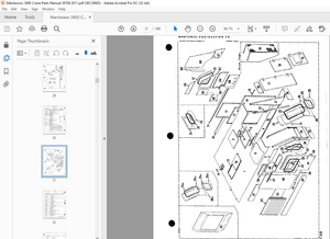
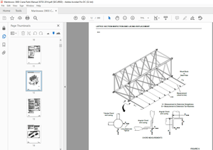
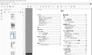
IMAGES PREVIEW OF THE MANUAL:
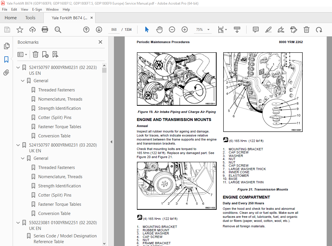
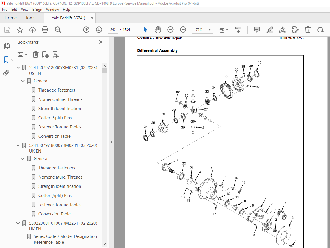
TABLE OF CONTENTS:
Yale Forklift B674 (GDP160EF9, GDP160EF12, GDP180EF7.5, GDP180EF9 Europe) Service Manual – PDF DOWNLOAD
524150797 8000YRM0231 (02 2023) US EN 1
General 7
Threaded Fasteners 7
Nomenclature, Threads 7
Strength Identification 8
Cotter (Split) Pins 9
Fastener Torque Tables 14
Conversion Table 16
524150797 8000YRM0231 (03 2020) UK EN 23
General 27
Threaded Fasteners 27
Nomenclature, Threads 27
Strength Identification 28
Cotter (Split) Pins 29
Fastener Torque Tables 34
Conversion Table 36
550223081 0100YRM2251 (02 2020) UK EN 43
Series Code / Model Designation Reference Table 49
General 49
Precautions 49
Section 1 – Cab Repair 50
Operator’s Cab Assembly 50
Tilting the Cab 50
Raising 50
Lowering 51
Remove 52
Install 54
Cab Tilt System 55
Hand Tilt Pump 55
Remove 55
Install 57
Electric Tilt Pump 57
Remove 57
Install 58
Cab Tilt Cylinder 59
Remove 59
Install 60
Latch 61
Remove 61
Install 62
Cab Windows 62
Window Replacement 62
Front Window 62
Remove 62
Install 62
Rear Window 63
Remove 63
Install 63
Top Window 63
Remove 63
Install 63
Door Window 63
Remove 63
Install 64
Sliding Window and Sliding Tracks 64
Remove 64
Install 65
Weather Strip Replacement 65
Window Stopper Replacement 65
Sliding Window Frame 65
Remove 65
Install 65
Window Wipers 66
Window Wiper Assembly Replacement 66
Remove 66
Install 66
Front Window Wiper Motor Assembly 66
Remove 66
Install 67
Rear Window Wiper Motor Assembly 67
Remove 67
Install 67
Top Window Wiper Motor Assembly 68
Remove 68
Install 68
Window Washer System 68
Window Washer Reservoir and Pumps 68
Remove 68
Install 69
Window Washer Hoses 69
Remove 69
Install 70
Window Washer Spray Nozzles 70
Front Window 70
Remove 70
Install 70
Rear Window 70
Remove 70
Install 70
Top Window 70
Remove 70
Install 70
Cab Door Assembly 71
Cab Door 71
Remove 71
Install 71
Door Hinge 72
Remove/Install 72
Door Latch 73
Remove 73
Install 73
Door Handle 73
Remove 73
Install 74
Door Release 74
Remove 74
Install 74
Door Push Button 75
Remove 75
Install 75
Steering Wheel and Steering Column Assembly 75
Steering Wheel and Horn 75
Remove 75
Install 77
Steering Column Assembly 77
Remove 77
Install 78
Shift Lever 78
Remove 78
Install 78
Gear Selection Lever 79
Remove 79
Install 79
Turn Signal Lever 79
Remove 79
Install 79
Pedals 79
Brake and Inching Pedal 79
Remove 79
Install 80
Accelerator Pedal and Sensor 80
Remove 80
Install 80
Adjust Sensor 81
Power Assist Armrest 81
Remove 81
Install 82
Armrest Components 83
Electrical Mini-Levers 83
Remove 83
Install 83
Armrest Switch Groups 84
Remove 84
Install 84
Ignition Key Switch and Start/Stop Button Switch 85
Remove 85
Install 85
Joystick 86
Remove 86
Install 86
USB Power Socket 87
Remove 87
Install 87
12V Power Socket 87
Remove 87
Install 88
Display Replacement 88
Seat Assembly 89
Remove 89
Install 89
Initialize New Seat 89
Cab Interior 90
Floor Mat 90
Remove 90
Install 90
Radio Console 91
Remove 91
Install 91
Air Duct Replacement 91
Remove 91
Install 92
Accessories 92
Mirror Replacement 92
Sunshade Replacement 93
Top 93
Rear 93
Map Light Replacement 93
Interior Fan Replacement 93
Training Seat 94
Field Installation 94
Remove 94
Checks and Adjustments 94
Label Check and Replacement 94
Cab Tilt System Oil Level Check 94
Door Striker Pin Adjustment 95
Section 2 – Cab Heater and Air Conditioner Repair 96
Heater Assembly 96
Access 96
Remove 97
Install 98
Heater Parts 99
Heater Core 99
Remove 99
Install 100
Water Valve 100
Remove 100
Install 101
Heater/Air Conditioning Assembly 101
Remove 101
Install 103
Filtration 103
Fresh Air Filter 103
Remove 103
Install 104
Air Conditioning Technical Detail 105
Maintenance, Service and Repairs 105
Safety Precautions 105
General Statements for Maintenance and Repairs 106
Residual Pressure 106
Refrigeration Circuit 106
Cooling Water Circuit 106
Maintenance Intervals 106
Repairs 107
Checklist 107
550223082 0700YRM2252 (02 2020) UK EN 111
Series Code / Model Designation Reference Table 115
General 115
Precautions 115
Cooling System 116
Cooling Core Assembly 116
Remove 117
Disassemble 122
Assemble 122
Install 123
Cooling System Components 125
Cooling Fan 125
Remove 125
Install 126
Checks and Adjustments 126
Cooling System Checks 126
Basic Checks 127
Coolant Quality Checks 127
Coolant Flow Checks 128
Thermostat 128
Water Pump 128
Cooling Core Efficiency 129
Cooling Core Flow Restrictions 129
Engine Leak Tests 129
External Leak Test 129
Check for Coolant Leak Into The Engine Oil Sump 130
Combustion Leak Test 131
Engine Cooling System Maintenance 131
Draining the Engine Cooling System 131
Filling the Engine Cooling System 132
Flushing the Engine Cooling System 132
Cleaning the Engine Cooling System 133
550223083 0900YRM2253 (03 2020) UK EN 135
Series Code / Model Designation Reference Table 143
General 143
Precautions 143
Special Tools 144
Section 1 – Drive Shaft Repair 145
Drive Shaft Assembly 145
Remove 145
Disassemble 147
Clean and Inspect 147
Assemble 147
Install 148
Section 2 – Engine and Transmission Repair 148
Engine and Transmission Assembly 148
Remove 148
Precautions 148
Remove Air Conditioning Compressor 149
Drain the Engine Cooling System 150
Drain Hydraulic Oil 151
Drain Transmission Oil 151
Disconnect Drive Shaft, Fan Clutch, Tubes, Pipes, Cables, Wires and Lines 151
Remove Engine and Transmission 156
Install 159
Install Engine and Transmission 159
Install Air Conditioning Compressor 160
Connect Drive Shaft, Fan, Tubes, Pipes, Cables, Wires and Lines 160
Refill the Systems 160
Starting the Engine 161
Engine Repair 162
Transmission Assembly 163
Remove 163
Install 165
Transmission Components 168
Disassemble 168
Transmission Case, Disassemble 168
Oil Pump, Disassemble 175
Clutch K3, Third Speed, Disassemble 177
Clutch K2, Second Speed, Disassemble 183
Clutch KR, Reverse, Disassemble 190
Clutch KV, Forward, Disassemble 197
Input Shaft, Disassemble 204
Clutch K1, First Speed, Disassemble 205
Clean and Inspect 211
Housings 211
Oil Seals and Gaskets 211
Bearings 212
Gears and Shafts 212
Assemble 213
Clutch K1, First Speed, Assemble 213
Input Shaft, Assemble 221
Clutch KV, Forward, Assemble 222
Clutch KR, Reverse, Assemble 231
Clutch K2, Second Speed, Assemble 240
Clutch K3, Third Speed, Assemble 249
Oil Pump, Assemble 257
Transmission Case, Assemble 259
Transmission Oil Filter Assembly 268
Clean 270
Inspect 270
Transmission Control Valve 271
Clean 276
Inspect 276
Transmission Test and Calibration 283
Precautions 283
Transmission Oil Sampling 283
Preparation 283
Sampling Procedure 283
Stall Test 283
Stall Test Procedure 283
Inch Pedal Calibration 284
Brake and Inch Pedal Adjustment 284
Inch Sensor Adjustment 285
Inch Pedal Calibration 285
Preparation 285
Calibration Procedure 286
Clutch Calibration 286
Control Valve Pressure Checks 286
Speed and Temperature Sensor Checks 289
Electrical Specifications 289
Section 3 – Engine Intake and Exhaust Repair 291
Air Filter Assembly 291
Remove 291
Install 291
Exhaust System (Tier 3/Stage IIIA) 293
Remove 293
Install 294
Exhaust System (Tier 4F/Stage IV) 294
Exhaust Pipes High Mount 294
Remove 294
Install 294
Exhaust Pipes and Diffuser Low Mount 296
Remove 296
Install 296
Engine After Treatment (EAS) System (Tier4F\Stage IV) 296
Engine After Treatment System Assembly 297
Preparation 297
Remove 298
Install 299
Engine After Treatment (EAS) System Components 299
Exhaust Seal Rings 299
Selective Catalytic Reducer (SCR) 300
Remove 300
Install 300
Decomposition Reactor Tube (DRT) 300
Remove 300
Install 301
Diesel Oxidation Catalyst (DOC) 301
Remove 301
Install 301
DEF System 302
DEF System Assembly 302
DEF System Components 302
DEF Tank 302
Remove 302
Install 303
DEF Tank Fill Cap 304
DEF Tank Unit 304
Remove 304
Install 304
DEF Tank Suction Filter 304
Replace 304
DEF Pump Assembly 305
Remove 305
Install 306
DEF Pump Filter 306
Replace 306
DEF Dosing Valve 307
Remove 307
Install 307
DEF System Checks and Adjustments 308
DEF Dosing Valve 308
DEF Pump 308
Fuel Tank 308
Remove 308
Clean and Repair 310
Install 310
Section 4 – Drive Axle Repair 311
Drive Axle Assembly 311
Remove 311
Install 313
Drive Axle Components 314
Planetary Gear Assembly 314
Preparations 315
Repairing and Replacing Parts 320
Welding 320
Clean 320
Ground or Polished Parts 320
Parts With Rough Finishes 321
Axle Assemblies 321
Drying Cleaned Parts 321
Preventing Corrosion 321
Inspect 321
Service Brake Assembly 326
Remove Service Brake 328
Clean 332
Ground and Polished Parts 333
Parts With Rough Finish 333
Wet Disc Brake and Axle Assembly 333
Inspect 333
Face Seals 333
Disc 334
Wear Limits 334
Replace Parts 335
Differential Assembly 341
Preparations 343
Remove 343
Differential Carrier From Axle Housing 343
Main Differential and Ring Gear Assembly From Differential Carrier 344
Drive Pinion and Pinion Carrier From Differential Carrier 346
Disassemble 349
Main Differential and Ring Gear Assembly 349
Drive Pinion, Bearings, and Pinion Carrier 350
Clean and Inspect 353
Assemble 353
Drive Pinion, Bearings, and Pinion Carrier 353
Pinion Bearings Preload Adjustment 355
Press Method 355
Flange Method 356
Triple-Lip Oil Seal 357
Pinion Carrier Shim Set Thickness Adjustment (Depth of Pinion) 358
Main Differential and Ring Gear Assembly 360
Differential Gears Rotating Torque 362
Install 363
Differential and Ring Gear Assembly 363
Differential Bearings Preload Adjustment 365
Method 1 365
Method 2 366
Ring Gear Runout Check 367
Ring Gear Backlash Adjustment 367
Tooth Contact Pattern Check 369
Thrust Screw Installation and Adjustment 372
Differential Carrier Into Axle Housing 372
Parking Brake 373
Preparations 374
Parking Brake Caliper 375
Remove 375
Disassemble 375
Clean and Inspect 376
Assemble 376
Install 376
Parking Brake Caliper Pads 377
Remove 377
Install 377
Drive Axle Checks and Adjustments 377
Oil Drain and Refill Procedures 377
Differential 377
Drain 377
(Re)Fill 378
Hub Assembly 378
Drain 378
(Re)Fill 378
Service Brake 379
Drain 379
(Re)Fill and De-aerate 379
Wheel Bearing Preload 379
Adjust 379
Parking Brake Adjustments 379
Parking Brake Bleed 379
Parking Brake Emergency Release 380
Park Brake Selector Valve Check 380
Park Brake Selector Valve Coil Check 380
Accumulator Pre-Charge Check 381
Parking Brake Pads Adjustment 381
Condition Check, Shuttle Valve L in the Main Control Valve 382
Condition Check, Shuttle Valve N in the Main Control Valve 382
Condition Check, Priority Valve on the Main Control Valve 383
Pressure Check, Port MLS1 383
Drive Axle Torque Specifications 384
Section 5 – Steering Axle Repair 386
Steering Axle Assembly 386
Remove 386
Install 387
Steering Axle Components 387
Tie Rod 387
Remove 387
Clean and Inspect 388
Install 388
Steering Cylinder 388
Remove 388
Clean and Inspect 391
Assemble and Install 391
Hubs 392
Remove and Disassemble 392
Clean and Inspect 392
Assemble and Install 393
Spindle 394
Remove 394
Clean and Inspect 394
Assemble and Install 395
Steering Axle Checks and Adjustments 395
Maximum Steering Angle Adjustment 395
Torque Specifications 396
Wheel Nuts 396
Steering Cylinder 396
Torque Specifications 396
Steering Axle 396
Wheel Nuts 396
Steering Cylinder 396
550223084 1900YRM2254 (02 2020) UK EN 399
Series Code / Model Designation Reference Table 407
General 407
Precautions 407
Section 1 – Hydraulic System Repair 407
Main Control Valve 407
Remove 407
Clean 410
Inspect 410
Assemble 410
Install 411
Priority Valve (A) 413
Remove 413
Clean 413
Inspect 414
Component Functionality Test 414
Install 414
Check Valve (K) 414
Remove 414
Clean 414
Inspect 414
Component Functionality Test 414
Install 414
Check Valve (I) 414
Remove 414
Clean 414
Inspect 415
Component Functionality Test 415
Install 415
Check Valve (Q) 415
Remove 415
Clean 415
Inspect 415
Component Functionality Test 415
Install 415
Screen Cartridge (O) 415
Disassemble 415
Component Functionality Test 415
Assemble 416
Shuttle Valves (L) and (M) 416
Remove 416
Clean 416
Inspect 416
Component Functionality Test 416
Install 416
Logic Valve (N) 417
Remove 417
Clean 417
Inspect 417
Component Functionality Test 417
Install 417
Full Flow Relief Valve (C) (Relief Spool) 417
Remove 417
Clean 417
Inspect 418
Assemble 418
Install 418
Pilot Supply Valve (F) 418
Remove 418
Clean 418
Inspect 418
Assemble 418
Component Functionality Test 418
Install 418
Load Sense (LS) Relief Valve (H) and Full Flow Relief Valve (G) 418
Remove 418
Clean 418
Inspect 419
Component Functionality Test 419
Install 419
Load Sense Relief Valve (H) Adjustment 419
Full Flow Relief Valve (G) Adjustment 419
Load Sense Selector Valve (D) 419
Remove 419
Clean 419
Inspect 420
Assemble 420
Install 420
Lift Pressure Selector Valve (B) 420
Remove 420
Clean 420
Inspect 421
Assemble 421
Install 421
Variable Displacement Pump (Primary and Secondary) 421
Remove 421
Clean 423
Inspect 423
Install 423
Electrical Actuation Module 425
Remove 425
Clean 425
Inspect 425
Assemble 425
Install 425
Emergency Lowering Valve (Left Slice Only) 427
Remove 427
Clean 427
Inspect 427
Install 427
Load Sense and Pressure Controller Valve on Pump 427
Remove 427
Clean 428
Inspect 428
Assemble 428
Install 428
Carriage Valve 428
Remove 429
Clean and Inspect 429
Assemble 429
Install 430
Manual End Cap 430
Remove 431
Clean 431
Inspect 431
Assemble 431
Install 431
Tilt Lock Valve 431
Remove 431
Clean 433
Inspect 433
Assemble 433
Install 433
Lowering Control Valve 433
Remove 433
Clean 434
Inspect 434
Install 434
Hydraulic Tank 435
Remove 435
Inspect 437
Clean 437
Steam Cleaning Method 437
Chemical Solution Cleaning Method 438
Repair 438
Small Leaks 438
Large Leaks 438
Inspection after Repair 438
Install 439
Hydraulic Checks and Adjustments 440
Adjustment of Pressure Controller on Pump 440
Adjustment of Load Sense Controller on the Secondary Variable Pump 441
Adjustment of Load Sense Controller on the Primary Variable Pump 442
Hydraulic System Torque Specifications 443
Section 2 – Steering System Hydraulics Repair 444
Steering Control Unit 444
Remove 444
Install 445
Steering Cylinder 445
Remove 445
Clean and Inspect 448
Assemble and Install 448
Steering System Torque Specifications 449
Steering Control Unit 449
Steering Cylinder 449
Section 3 – Brake System Hydraulics Repair 449
Brake Treadle Valve 449
Remove 449
Install 450
Accumulator 451
Remove 451
Disassemble 451
Clean 454
Inspect 454
Repair 454
Assemble 454
Install 455
Pre-Charge Filling 455
Parking Brake 456
Parking Brake Caliper 456
Remove 456
Disassemble 457
Clean and Inspect 457
Assemble 458
Install 458
Parking Brake Caliper Pads 459
Remove 459
Install 459
Parking Brake Bleed 459
Parking Brake Emergency Release 460
Brake Flow Distribution Manifold 460
Remove 460
Disassemble 462
Clean and Inspect 462
Assemble 462
Install 462
Brake Control Manifold 463
Remove 463
Install 464
Orifices (F) and (G) 464
Disassemble 464
Assemble 464
Orifice (H) 464
Disassemble 464
Assemble 465
Unloading Valve (B) 465
Disassemble 465
Assemble 465
Screen 465
Disassemble 465
Assemble 465
Check Valve (E) 465
Disassemble 465
Assemble 465
Pressure Reducer Valve (C) 466
Disassemble 466
Assemble 466
Park Brake Selector Valve (A) 466
Disassemble 466
Assemble 466
Brake System Checks and Adjustments 467
Hydraulic Pressure Checks Preparation 467
Park Brake Selector Valve Check 467
Park Brake Selector Valve Coil Check 467
Accumulator Pre-Charge Check 468
Parking Brake Adjustment 468
Condition Check, Shuttle Valve (L) in the Main Control Valve 469
Condition Check, Shuttle Valve (N) in the Main Control Valve 469
Condition Check, Priority Valve on the Main Control Valve 469
Pressure Check, Port MLS1 470
Hydraulic Brake Torque Specifications 470
Hydraulic Hose Torque Procedure 471
Section 4 – Cylinder Repair 471
Front End Cylinders 471
Side Shift Cylinder 471
Disassemble 471
Clean and Inspect 472
Assemble 472
Fork Positioner Cylinder 472
Disassemble 472
Clean and Inspect 473
Assemble 473
Tilt Cylinders 474
Disassemble 474
Clean and Inspect 474
Assemble 474
De-Aeration of the Tilt Cylinders before Start-up 476
Lift Cylinders 476
Disassemble 476
Clean and Inspect 477
Assemble 477
550223085 2200YRM2255 (02 2023) US EN 479
Series Code / Model Designation Reference Table 485
General 485
Section 1 – Electrical 485
General Fault Finding 485
Preparation 485
Define the Problem Area 485
Identify Possible Causes of Malfunction 485
Determine the Most Probable Cause 485
Fuse Check 485
Wiring Check 486
Component Check 486
Repair and Test 486
Harnesses and Connectors 486
Harnesses Overview 486
Harness Connectors and Terminals 488
Frame Harness Connectors 489
Cab Rear Wall Harness Connectors 493
Mast Harness Connectors 496
Mast Work Lights and Lights Extension Harness Connectors 496
Closed Cab Harness Connectors 497
Steering Column Harness Connectors 501
Cab Tilt Harness Connectors 502
Cab Lights Harness Connectors (LH harness shown) 504
ECM Harness Connectors (Tier 3/Stage IIIA Engine) 506
EAS/ECM Harness Connectors (Tier 4F/Stage IV Engine) 507
DEF Tank Harness Connectors (Only Tier 4F/Stage IV Engine) 509
Powertrain Harness Connectors 510
Hoodspine Harness Tier 3/Stage IIIA Connectors 512
Hoodspine Harness Tier 4F/Stage IV Connectors 512
Carriage Harness Connectors 513
Rear Harness Connectors 514
Wire Harness Identification and Connector Location 517
Fuses and Relays 517
Fuse Relay Board 522
CANbus Circuit 524
Greasing System Electrical 525
Section 2 – Controls 527
Information Display 527
General 527
Information Display Overview 528
Information Display Diagram and Connectors 529
Fault Codes 531
Transmission Calibration 531
Section 3 – User Interface Display 532
Navigation Key 532
Startup Sequence 533
Home Screen 534
Screen Brightness Menu 535
HVAC Controls Menu 536
Logging in 537
Log In/Out 537
View the fault log 538
Fault Log 538
View the hardware and software versions 539
Calibrations 540
Calibrate the clutch pack 540
Calibrate the brake pedal 541
Calibrate the accelerator pedal 541
Calibrate the load weight sensor 541
Diagnostics Menu 542
Hydraulics 542
H1d 1st Hyd Function 543
H2d 2nd Hyd Function 543
Aux Hyd Functions 543
Drive 543
D1 Engine 544
D9 Transmission 544
Controllers 544
C1d VSM 544
C10d Hydraulic Controller 1 544
C11d Armrest Module 544
C12d High Current Module 545
C99d Light module 545
Overview 545
Settings 545
Hydraulics 545
Operators 546
Truck Setup 546
T1 Display 547
T2 Lights 547
T5 Switches 547
Display Flow Chart 547
550223085 2200YRM2255 (03 2020) UK EN 557
Series Code / Model Designation Reference Table 561
General 561
Section 1 – Electrical 561
General Fault Finding 561
Preparation 561
Define the Problem Area 561
Identify Possible Causes of Malfunction 561
Determine the Most Probable Cause 561
Fuse Check 561
Wiring Check 562
Component Check 562
Repair and Test 562
Harnesses and Connectors 563
Harnesses Overview 563
Harness Connectors and Terminals 563
Frame Harness Connectors 564
Cab Rear Wall Harness Connectors 567
Mast Harness Connectors 570
Mast Work Lights and Lights Extension Harness Connectors 570
Closed Cab Harness Connectors 571
Steering Column Harness Connectors 575
Cab Tilt Harness Connectors 576
Cab Lights Harness Connectors (LH harness shown) 578
ECM Harness Connectors (Tier 3/Stage IIIA Engine) 580
EAS/ECM Harness Connectors (Tier 4F/Stage IV Engine) 581
DEF Tank Harness Connectors (Only Tier 4F/Stage IV Engine) 583
Powertrain Harness Connectors 584
Hoodspine Harness Tier 3/Stage IIIA Connectors 586
Hoodspine Harness Tier 4F/Stage IV Connectors 586
Carriage Harness Connectors 587
Rear Harness Connectors 589
Wire Harness Identification and Connector Location 591
Fuses and Relays 591
Fuse Relay Board 596
CANbus Circuit 598
Greasing System Electrical 599
Section 2 – Controls 601
Information Display 601
General 601
Information Display Overview 602
Information Display Diagram and Connectors 603
Fault Codes 605
Transmission Calibration 605
Section 3 – User Interface Display 606
Navigation Key 606
Startup Sequence 607
Home Screen 608
Screen Brightness Menu 609
HVAC Controls Menu 610
Logging in 612
Log In/Out 612
View the fault log 613
Fault Log 613
View the hardware and software versions 614
Calibrations 614
Calibrate the clutch pack 615
Calibrate the brake pedal 615
Calibrate the accelerator pedal 616
Calibrate the load weight sensor 616
Diagnostics Menu 616
Hydraulics 617
H1d 1st Hyd Function 617
H2d 2nd Hyd Function 618
Aux Hyd Functions 618
Drive 618
D1 Engine 618
D9 Transmission 618
Controllers 619
C1d VSM 619
C10d Hydraulic Controller 1 619
C11d Armrest Module 619
C12d High Current Module 619
C99d Light module 619
Overview 619
Settings 620
Hydraulics 620
Operators 621
Maintenance 621
Truck Setup 621
T1 Display 621
T2 Lights 622
T5 Switches 622
Display Flow Chart 622
550223086 2400YRM2256 (02 2020) UK EN 633
Series Code / Model Designation Reference Table 637
General 637
Greasing System 638
Grease Pump Assembly 638
Remove 639
Install 639
Greasing System Components 639
Grease Line Identification 639
Grease Reservoir 643
Disassemble 643
Assemble 644
Refilling the Grease Reservoir 644
Test Cycles Using the Button on the Pump 645
Bleeding the Pump 645
Bleeding the System 646
Checks and Adjustments 661
Test Procedures 661
Check pressure switch (valve) and cable 661
Check pump and 5/2-way valve 661
Check for Internal System Leaks 662
Technical Data 663
Pump Unit 663
Grease Recommendations 663
Electrical 663
Torque Specifications 665
550223087 4000YRM2257 (02 2020) UK EN 667
Series Code / Model Designation Reference Table 673
General 673
Safety Procedures 673
When Working Near The Mast Always 673
When Working on the Hydraulic System 673
Section 1 – Forks and Carriage Repair 674
Forks 674
Pin-Type Forks 675
Remove 675
Install 677
Quick Disconnect DFSSFP Forks 677
Remove 677
Install 678
Integrated DFSSFP Forks 678
Remove 678
Clean and Inspect 679
Install 680
Fork Hanger for Quick Disconnect Forks 680
Remove 680
Clean and Inspect 680
Install 680
Carriage Assembly 681
Carriage Types 681
Remove 684
Install 685
Carriage Components 686
Carriage Bearing Blocks 686
Remove 686
Install 686
Carriage Load Rollers 687
Remove 687
Install 688
Apron Wear Pads (DFSSFP Carriage) 688
Replace 688
Fork Position Cylinder 689
Remove 689
Install 691
Side Shift Cylinder 691
Remove 691
Install 692
Carriage Valve 692
Remove 692
Install 693
Section 2- Mast Repair 694
Mast Assembly 694
Remove 694
Disassemble 696
Assemble 698
Install 698
Inner Mast Load Rollers 700
Remove and Disassemble 700
Assemble and Install 701
Mast Bearing Blocks 701
Remove 701
Install 701
Lift Cylinders 702
Remove 702
Install 703
Mast Components 704
Lift Chains 704
Remove 704
Install 705
Chain Anchor On Carriage 705
Remove 705
Install 706
Top Chain Anchor 706
Remove 706
Install 706
Chain Sheave 706
Remove 706
Install 707
Header Hoses 708
Remove 708
Install 709
Electric Mast Cable 709
Remove 709
Install 710
Hose Sheave 710
Remove and Disassemble 710
Assemble and Install 711
Tilt Cylinder 711
Remove 711
Install 712
Mast Checks and Adjustments 713
General Checks 713
Mast Condition Check 713
Mast Operation Check 713
Fork Inspection 713
Lift Chains 714
Lift Chains Cleaning 714
Lift Chain Inspection 715
Lift Chain Lubricant Requirements 716
Lift Chain Lubrication Procedure 716
Leak Checks 716
Mast Vertical Creep 716
Mast Tilt Drift 717
Adjustments 717
Lift Cylinder Shimming 717
Lift Chain and Fork Height Adjustment 719
Dual Function Fork Guide Shimming 720
Header Hose Tension Adjustment 721
Electric Mast Cable Tension Adjustment 721
Tilt Cylinder Backward Tilt Adjustment 721
Mast Support Pad Adjustment 722
Torque Specifications 723
Torque Values for Mast and Carriage 723
Tightening Torques 724
550223088 8000YRM2258 (01 2020) UK EN 729
Series Code / Model Designation Reference Table 733
Counterweight Weights 733
Lift Truck Weights 733
Capacities 733
Electrical System 734
Engine Specifications 734
Mast Speeds 735
Tire Sizes 735
Hydraulic System 736
Torque Specifications, General 736
Transmission ZF 736
Counterweight 736
Steering 736
Wheel Nuts 737
Hydraulic System 737
Mast 737
Carriage 737
Tilt Cylinders 737
Torque Specifications, Cummins Diesel 738
Lubrication System 738
550223089 8000YRM2259 (03 2020) UK EN 741
Series Code / Model Designation Reference Table 745
Electrical Schematic T3/T4 Final 746
Hydraulic Schematic 774
550223089 8000YRM2259 (10 2022) US EN 781
Series Code / Model Designation Reference Table 787
Electrical Schematic T3/T4 Final 788
Hydraulic Schematic 816
550223090 8000YRM2260 (03 2020) UK EN 823
Series Code / Model Designation Reference Table 827
General 827
Precautions 827
Main Components 828
Hood Assembly 828
Remove 828
Install 829
Running Boards, Steps and Mud Flaps 830
Counterweight 831
Remove 831
Install 833
Label Replacement 834
550223092 8000YRM2262 (07 2020) UK EN 837
Series Code / Model Designation Reference Table 843
General 843
Serial Number Data 843
Truck Handling Procedures 844
Moving and Towing a Lift Truck 844
Precautions 844
Towing the Truck 845
Putting a Lift Truck on Blocks 845
Raising the Drive Tires 845
Raising the Steering Tires 846
Cleaning a Lift Truck 847
Safety Procedures Before Starting Maintenance 848
Making Checks From the Driver Seat with Engine Running 848
Fire Hazard 848
Wait 100 Seconds Before Disconnecting Battery 848
Periodic Maintenance Schedule 849
Daily Inspection 850
Daily Condition Checks 850
Daily Fluid Level Checks 850
Daily Checks from the Driver Seat with Engine Running 851
Initial Inspection 852
First Inspection after First 20 and First 40 Hours of Operation 852
First Inspection after First 100 Hours of Operation 852
First Inspection after First 250 Hours of Operation 853
Periodic Maintenance 853
Inspect and Adjust 853
Annual Inspection 855
Lubricate 857
Change 858
Periodic Maintenance Procedures 860
Air Conditioning System 860
Automatic Greasing System (Optional) 860
Greasing System 860
Greasing System Filter 860
Brake Cooling Filter 861
Brake System Accumulator 861
Cab Air Filter 862
Control Levers, Switches, and Pedals 862
Cooling System 862
Coolant Hoses 862
Coolant Level 863
Coolant Quality 863
Cooling Fan 863
Crankcase Breather Element (Tier 4F/Stage IV Only) 863
Diesel Exhaust Fluid (DEF) System 864
DEF Pump Filter 864
DEF Tank Fill Cap 865
DEF Tank Suction Filter 865
Drive Axle, Differential and Axle Hub Assembly 866
Check Oil level 866
Change Oil 866
Drive Wheel Hub Bearing Preload 866
Drive Shaft 866
Engine Air Filter 867
Engine Air Intake Piping and Charge Air Piping 867
Engine and Transmission Mounts 868
Engine Compartment 868
Engine Drive Belt 869
Engine Drive Belt Tensioner and Pulleys 869
Bearing Condition 869
Pulley Alignment 869
Tensioner Condition 869
Engine Oil 871
Engine Oil Level 871
Engine Oil and Engine Oil Filter 871
Engine Valve Adjustment 872
Fault Codes 874
Forks 874
Fork Guide Bearing Blocks 875
Fork Guide Wear Pads 876
Fork Pins, Carriage Pins, and Carriage Sliding Surfaces 876
Frame, Mast and Carriage 876
Fuel, Oil, DEF, or Coolant Leaks 877
Fuel/Water Separator and Final Fuel Filter 877
Fuel Tank Breather 878
Header Hose Assembly 878
Horn, Gauges, Lights, Alarms and Control System 878
Hydraulic System Oil 878
Hydraulic Oil Testing Procedures 879
Hydraulic Oil Replacement 879
Hydraulic Tank Breather 881
Hydraulic Tank Return Filter 881
Inching Pedal Sensor Calibration 881
Lift Chains 881
Check and Lubricate Lift Chains 881
Adjust Lift Chains 882
Inspect Lift Chains 883
Chain Elongation 883
Lift Chain Wear and Damage 884
Lift System Accumulator (Optional) 884
Load Rollers 884
Carriage Load Rollers 884
(Inner) Mast Load Rollers 885
Mast and Carriage 885
Mast Pivot Pins 885
Operator Presence System 886
Operator Restraint System 886
Seat Belt and Seat Rails 886
Steering Column Pedal 887
Parking and Service Brakes 887
Radiator Assembly 887
Steering Axle Grease Fittings 887
King Pins 887
Tie Rod Pins 887
Pivot Pin 887
Steering System 888
Steering Wheel Hub Bearings 888
Remove and Disassemble 888
Clean and Inspect 889
Assemble and Install 889
Tilt Cylinder Pivot Pins 890
Transmission 891
Transmission Clutch Calibration 891
Transmission Oil Level 891
Transmission Oil and Oil Filter 891
Turbo Charger 892
Vibration Damper (Viscous) 892
Warning and Safety Labels 893
Windows and Mirrors 893
Windshield Washer Fluid Level 893
Wheels and Tires 893
Wheels, Tires, and Tire Pressure 893
Remove Wheels from Lift Truck 894
Adding Air Pressure to Pneumatic Tires 900
Install Wheels on Lift Truck 904
Capacities and Specifications 906
Approved Fuel and Engine Oils 906
Approved Oils, Fluids, and Grease 906
Engine Oil Viscosity 907
Lift Chain Lubricant Requirements 908
Electrical Components 908
Cab Electric Group 908
Check the Fuses 908
Power Distribution Group 911
550223093 8000YRM2263 (04 2020) UK EN 917
Series Code / Model Designation Reference Table 921
General 921
Weight and Dimensions 922
Loading Procedures 926
Loading A Truck on a Transport 926
Loading Disassembled Components 926
Unloading Procedures 927
Unloading A Truck From Transport 927
Lifting a Truck 927
Driving a Truck Off a Trailer 927
Unloading Disassembled Components 927
Moving and Towing 928
Moving a Disabled Lift Truck 928
Precautions 928
Towing A Lift Truck 928
Safety Procedures When Working Near The Mast 929
When Working Near The Mast Always 929
Before Starting Repairs To The Hydraulic System Always 930
Truck Assembly 931
Mast Installation 931
Preparations 931
Installing the Mast 931
Installing the Tilt Cylinders 932
Adjusting the Tilt Cylinders 933
Connecting the Lift Cylinders 934
Connecting the Mast Supply Hoses 934
Carriage and Forks 935
Installing the Carriage 935
Connecting the Header Hoses to the Carriage 935
Install the Forks 936
Installing Pin-Type Forks 936
Installing Quick Disconnect DFSSFP Forks 938
Installing Integrated DFSSFP Forks 939
Adjusting the Carriage 939
Adjusting Header Hose Tension 940
Adjusting the Electrical Cable Tension 941
Installing the Cab Lights 941
Lubrication Points 942
General Checks After Assembly 942
Plumbing Check 942
Lubrication Check 942
Fluid Level Check 942
Functionality Check 942
Literature Package Check 942
Cleaning 942
Labels 942
Wheels and Tires 943
Remove Wheels From Lift Truck 943
Remove Tire From Wheel 944
Install Tire on Wheel 945
Adding Air Pressure to Tires 946
Install Wheels on Lift Truck 947
Capacities and Specifications 948
Torque Values 948
Pre-Delivery 948
Perform Pre-Delivery Inspection 948
Delivery 948
Instructions Operating Manual 948
Instructions Daily Maintenance 948
Handing Over Truck 948
550223094 8000YRM2264 (02 2020) UK EN 951
Model Designation / Series Code 955
General 955
Section 1 – Troubleshooting 955
Cab Heater and Air Conditioning 955
Preliminary Checks 955
Checking System Air Output 955
Check The Sight Glass for Bubbles 955
Troubleshooting Procedures 955
General System 956
Climate Control Display Diagnostics Menu Errors 958
Mast 959
Section 2 – Error Codes 962
Cummins Engine 962
General 962
Fault Code Descriptions 962
Finding Fault Code Information 962
Electronic Throttle Calibration 962
Stationary Regeneration Procedure 963
ZF Transmission Codes 1016
Hydraulic Control System Fault Codes 1059
VSM 1063
Automatic Greasing System 1075
General Instructions and Safety Information 1075
Test Procedures 1080
Procedure to check pressure switch (valve) and its cable 1080
Procedure to check pump and 5/2-way valve 1081
Procedure when an internal system leak is suspected 1081
550223094 8000YRM2264 (08 2022) US EN 1085
Model Designation / Series Code 1091
General 1091
Section 1 – Troubleshooting 1091
Cab Heater and Air Conditioning 1091
Preliminary Checks 1091
Checking System Air Output 1091
Check The Sight Glass for Bubbles 1091
Troubleshooting Procedures 1092
General System 1092
Climate Control Display Diagnostics Menu Errors 1094
Mast 1095
Section 2 – Error Codes 1098
Armrest 1098
Cabin Tip 1106
Communications 1107
Engine (Cummins) 1109
Cummins Engine 1109
General 1109
Fault Code Descriptions 1110
Finding Fault Code Information 1110
Electronic Throttle Calibration 1110
Stationary Regeneration Procedure 1110
Engine (Mercedes-Benz) 1154
General 1154
Finding Fault Code Information 1154
ACM Faults 1154
CPC4 Faults 1177
MCM Faults 1204
Greasing (Frame) 1245
Greasing (Spreader) 1246
Heating Ventilation and Air Conditioning (HVAC) 1247
Hydraulic Controller 1249
Hydraulic Controller 1 1249
Hydraulic Controller 2 1250
Spreader 1250
Telemetry 1261
TPMS 1261
Transmission (ZF) 1262
VSM 1304
Other 1332
More products