$36.95
Yale Forklift B810 (GDP030-040AF) Service Manual - PDF
Yale Forklift B810 (GDP030-040AF) Service Manual – PDF DOWNLOAD
FILE DETAILS:
Yale Forklift B810 (GDP030-040AF) Service Manual – PDF DOWNLOAD
Language : English
Pages : 756
Downloadable : Yes
File Type : PDF
PART NO. 524150775
IMAGES PREVIEW OF THE MANUAL:
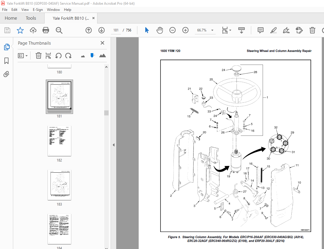
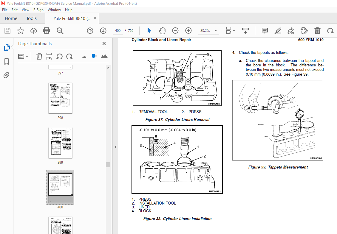
TABLE OF CONTENTS:
Yale Forklift B810 (GDP030-040AF) Service Manual – PDF DOWNLOAD
524150775 0700YRM0626 (03 2003) US EN 1
toc 1
Cooling System 1
Safety Precautions Maintenance and Repair 2
General 5
Description 6
Radiator 6
Radiator Cap 6
Thermostat 6
Water Pump 7
Fan and Fan Shroud 7
Cooling System Checks 7
Radiator 7
Thermostat 7
Water Pump 8
Exhaust Leaks 8
Fan and Fan Shroud 8
Radiator Cleaning 8
Drain 8
Clean 8
Fill 9
Troubleshooting 10
524150790 2100YRM0103 (03 2007) US EN 13
toc 13
Tilt Cylinders 13
Safety Precautions Maintenance and Repair 14
General 17
Description 17
Tilt Cylinder Repair 17
Remove 17
Disassemble 17
Clean 17
Assemble 18
Tilt Cylinders With O-Ring or Single-Lip Seals 18
Tilt Cylinders 19
Install 20
Tilt Cylinder Leak Check 22
Tilt Cylinder Stroke and Mast Tilt Angle Adjustment 23
Torque Specifications 23
Piston Rod Nut 23
Retainer 23
Troubleshooting 24
tables 13
Table 1 Movement Rates (Maximum) for Tilt Cylinders 22
524150797 8000YRM0231 (02 2023) US EN 29
General 35
Threaded Fasteners 35
Nomenclature, Threads 35
Strength Identification 36
Cotter (Split) Pins 37
Fastener Torque Tables 42
Conversion Table 44
524150797 8000YRM0231 (03 2020) US EN 51
General 55
Threaded Fasteners 55
Nomenclature, Threads 55
Strength Identification 56
Cotter (Split) Pins 57
Fastener Torque Tables 62
Conversion Table 64
524158742 0600YRM0496 (01 2011) US EN 71
toc 71
Mazda Engine 71
Safety Precautions Maintenance and Repair 72
General 75
Description 75
Engine Removal and Installation 75
Cylinder Head, Camshaft, and Valve Mechanism Repair 76
Remove 76
Clean 77
Inspect and Repair 78
Cylinder Head 78
Rocker Shaft Assembly 78
Camshaft 78
Valve Guides 79
Valve Seats 80
Valves 80
Valve Springs 81
Install 81
Crankshaft and Main Bearings Repair 84
Remove 84
Inspect and Repair 84
Crankshaft 84
Main Bearings 84
Install 85
Pistons and Connecting Rods Repair 86
Remove and Disassemble 86
Clean 86
Inspect and Repair 86
Pistons 86
Piston Rings 87
Connecting Rods and Bearings 87
Assemble and Install 88
Cylinder Block Repair 89
Oil Pump Repair 89
Remove 89
Disassemble 90
Clean 90
Inspect 90
Assemble 91
Install 92
Cooling System Repair 92
Thermostat 92
Replace 92
Fan Assembly 92
Remove and Disassemble 92
Assemble and Install 93
Water Pump 93
Remove and Disassemble 93
Assemble and Install 94
Distributor Repair 95
Remove 95
Install 95
Flywheel and Ring Gear Repair 96
Remove 96
Ring Gear, Replace 96
Install 96
Flywheel Repair 97
Remove 97
Install 97
Valve Adjustment 98
Compression Pressure Check 98
Engine Timing Adjustment 99
Throttle Linkage Adjustment 99
Gasoline Engines 99
LPG Engines (IMPCO) 99
LPG Engines (AISAN) 100
Engine Specifications 100
Engine Data 100
Thermostat 100
Cylinder Head 100
Valve Mechanism 100
Camshaft 101
Crankshaft 101
Connecting Rods 102
Cylinder Block 102
Pistons 102
Oil Pump 102
Torque Specifications 103
Troubleshooting 104
524158747 0900YRM0925 (12 2003) US EN 109
toc 109
LPG Fuel System 109
Safety Precautions Maintenance and Repair 110
General 113
Description and Operation 113
Fuel Tank 114
Regulator 114
Start Mode 116
Idle Mode 116
Run Mode 116
Resonator 116
Carburetor 117
Start Mode 117
Idle Mode 117
Run Mode 117
Governor 118
Hoses Replacement 119
LPG Tank Repair 119
Remove 119
Install 119
Relief Valve Repair 120
Remove and Install 120
Carburetor Repair 120
Remove 120
Disassemble 120
Clean 121
Assemble 121
Install 122
Governor Repair 122
Remove 122
Inspect 122
Install 122
Regulator Repair 123
Remove 123
Disassemble 123
Clean 123
Inspect 123
Assemble 125
Install 126
Regulator Adjustment 126
Regulator Height Adjustment 126
Regulator Assembly Air Tightness Test 127
Carburetor Adjustment 128
Idle Speed and Fuel Mixture 128
Idle Control Adjustment 128
Governor Adjustment 129
Checks 129
Adjustments 129
Throttle Linkage Adjustment 130
Foot Directional Control Pedal Check 131
Throttle Linkage Adjustment 132
Troubleshooting 133
tables 109
Table 1 Power Adjusting Screw 122
Table 2 Air Adjusting Screw 122
Table 3 Idle Mixture Adjusting Screw 125
Table 4 Idle Mixture Adjusting Screw 128
524158748 0900YRM0948 (10 2006) US EN 141
toc 141
LPG Fuel System 141
Safety Precautions Maintenance and Repair 142
General 145
Description and Operation 145
Fuel Tank 145
Oxygen Sensor 145
Regulator 145
Start Mode 148
Idle Mode 151
Run Mode 151
Resonator 151
Carburetor 151
Start Mode 151
Idle Mode 152
Run Mode 152
Governor 153
Hoses Replacement 153
LPG Tank Repair 154
Remove 154
Install 154
Relief Valve Repair 155
Remove and Install 155
Carburetor Repair 155
Remove 155
Disassemble 155
Clean 156
Assemble 156
Install 157
Fuel Injector Repair 157
Remove 157
Clean and Inspect 157
Install 157
Governor Repair 158
Remove 158
Inspect 158
Install 158
Regulator Repair 158
Remove 158
Install 158
Oxygen Sensor Repair 158
Remove and Install 158
Vacuum Switches Repair 159
Remove and Install 159
Inspect 159
Resistor Repair 159
Remove and Install 159
Inspect 159
Carburetor and New Regulator Adjustment 159
Idle Speed and Fuel Mixture 159
Idle Control Adjustment 160
Governor Checks and Adjustments 161
Checks 161
Adjustments 161
Throttle Linkage Adjustment 161
Foot Directional Control Pedal Check 163
Check Engine Light 163
Inspect Warning Lamp 163
Check Feedback Operation 163
Check VAC1 and VAC2 Signals 163
Check Resistor 163
Check Fuel Injector 163
Check Oxygen Sensor 164
Check Vacuum Switch 1 164
Check Vacuum Switch 2 164
After Completing Checks 164
Troubleshooting 164
tables 141
Table 1 Adjusting Screw 157
524158753 1600YRM0720 (11 2006) US EN 173
toc 173
Steering Housing and Control Unit 173
Safety Precautions Maintenance and Repair 174
General 177
Description 177
Operation 178
Steering Wheel and Column Assembly Repair 179
Assembly Components, Remove 179
Steering Control Unit, Disassemble 184
Steering Control Unit, Clean 184
Steering Control Unit, Assemble 184
Assembly Components, Install 186
System Air Removal 188
Troubleshooting 188
524158757 2200YRM0514 (01 2004) US EN 193
toc 193
Instrument Cluster 193
Safety Precautions Maintenance and Repair 194
General 197
Description 197
Instrument Cluster Display Panel, Internal Combustion Lift Truck 197
Instrument Cluster Display Panel, Electric Lift Truck Models 204
Optional Basic Display Panel 204
Features of the Optional Basic Display Panel 204
Description of Features on the Optional Basic Display Panel 204
Standard Display Panel 205
Features of the Standard Display Panel 205
Description of Features on the Standard Display Panel 205
Premium Display Panel 206
Features on the Premium Display Panel 206
Description of Features on the Premium Display Panel 207
Curtis 1215 Display Panel 209
Description and Features 209
Operation 210
Cluster-Type Display Panel (Internal Combustion) Replacement 211
Remove 211
Install 211
Cluster Display Panel (Electric Lift Truck) Replacement 214
Curtis 1215 Display Panel Replacement 219
Remove 219
Install 219
tables 193
Table 1 Instrument Cluster, Internal Combustion 198
524158758 2200YRM0524 (12 2003) US EN 223
toc 223
Electrical System 223
Safety Precautions Maintenance and Repair 224
General 227
Description 227
Starting System 227
Ignition System 227
Charging System 228
Starter Repair 229
Remove and Disassemble 229
Assemble and Install 229
Coil Replacement 231
Distributor Repair 232
Remove and Disassemble 232
Assemble and Install 232
Distributor Repair 234
Remove and Disassemble 234
Assemble and Install 236
Alternator Repair 236
Remove and Disassemble 236
Assemble and Install 237
General Checks and Adjustments 238
Starter Checks 238
Operation, Check 238
Brush Holder, Check 239
Armature, Check 239
Field Windings, Check 239
Clutch and Bearing, Check 239
Ignition System Check and Adjustment 240
Engine Timing, Adjust 240
Spark Plugs, Check 240
Charging Circuit Checks 241
Low Output, Check 241
High Output, Check 242
Diodes, Check 242
Rotor Field Winding, Check 243
Stator Windings, Check 243
Brushes and Bearings, Check 243
Voltage Regulator, Check 243
Troubleshooting 244
524158890 4000YRM0521 (03 2006) US EN 249
toc 249
Mast 249
Safety Precautions Maintenance and Repair 250
General 253
Description and Operation 253
Carriages 253
Mast Mounts 255
Two-Stage Mast, Limited Free-Lift (LFL) 256
Description and Operation 256
Two-Stage Mast, Full Free-Lift (FFL) 258
Description and Operation 258
Three-Stage Mast, Full Free-Lift (FFL) 260
Description and Operation 260
Four-Stage Mast 262
Description and Operation 262
Cylinder Cushion During Lifting Sequence 266
Cylinder Cushion During Lowering Sequence 267
524158891 4000YRM0522 (07 2010) US EN 271
toc 271
Mast 271
Safety Precautions Maintenance and Repair 272
General 275
Safety Procedures When Working Near Mast 276
Fork Repair 278
Remove 278
Install 278
Carriages Repair 280
Standard Carriage, Remove 280
Hang-On Sideshift Carriage, Remove 281
Standard Carriage and Hang-On Sideshift Carriage, Repair 282
Standard Carriage, Install 283
Hang-On Sideshift Carriage, Install 284
Integral Sideshift Carriage 284
Remove 284
Clean and Inspect 288
Repair 289
Install 290
Mast Repair 291
Remove 291
Two-Stage LFL and Two-Stage FFL Masts, Disassemble 293
Three-Stage FFL Mast 301
Disassemble 301
Mast and Chains, Clean and Inspect 304
Two-Stage LFL and Two-Stage FFL Mast, Assemble 305
Three-Stage FFL Mast, Assemble 306
Install 307
Lift Cylinders Repair 309
Main Lift Cylinders, Remove 309
Free-Lift Cylinder, Remove 309
Cylinders, Disassemble 310
Two-Stage Full Free-Lift Mast, Right-Hand Main Lift Cylinder 310
Two-Stage Full Free-Lift Mast, Left-Hand Main Lift Cylinder 312
Two-Stage Limited Free-Lift Mast and Three-Stage Full Free-Lift 312
Two-Stage Limited Free-Lift Mast and Three-Stage Full Free-Lift 313
Two-Stage Full Free-Lift Mast and Three-Stage Full Free-Lift Mas 314
Clean and Inspect 315
Cylinders, Assemble 315
Two-Stage Full Free-Lift Mast, Right-Hand Main Lift Cylinder 315
Two-Stage Full Free-Lift Mast, Left-Hand Main Lift Cylinder 316
Two-Stage Limited Free-Lift Mast and Three-Stage Full Free-Lift 317
Two-Stage Limited Free-Lift Mast and Three-Stage Full Free-Lift 317
Two-Stage Full Free-Lift Mast and Three-Stage Full Free-Lift Mas 318
Main Lift Cylinders, Install 319
Free-Lift Cylinder, Install 319
Header Hose Arrangements 320
Two-Stage LFL Mast, New Hose Install 320
Two-Stage LFL Mast, Adjust Hoses After Installation 325
Two-Stage FFL Mast, New Hose Install 325
Two-Stage FFL Mast, Adjust Hoses After Installation 333
Three-Stage FFL Mast, New Hose Install 333
Three-Stage FFL Mast, Adjust Hoses After Installation 344
Header Hose Arrangement 345
Two-Stage LFL Mast, New Hose Install 345
Two-Stage LFL Mast, Adjust Hoses After Installation 350
Two-Stage FFL Mast, New Hose Install 350
Two-Stage FFL Mast, Adjust Hoses After Installation 356
Three-Stage FFL Mast, New Hose Install 356
Three-Stage FFL Mast, Adjust Hoses After Install 365
Lift and Tilt System Leak Check 366
Lift Cylinders Leak Check 366
Tilt Cylinders Leak Check 366
Tilt Cylinders Adjustment 367
Lift Chains Adjustment 369
Mast Adjustment 371
Carriage Adjustment 373
Troubleshooting 374
tables 271
Table 1 Hook-Type Carriage Chain Adjustment 369
Table 2 Pin-Type Carriage Chain Adjustment 370
524162461 0600YRM1019 (01 2011) US EN 377
toc 377
Mazda XA and HA Diesel Engines 377
Safety Precautions Maintenance and Repair 378
General 383
Description 383
Engine Removal and Installation 383
Cylinder Head and Valve Mechanism Repair 385
Remove 385
Clean 385
Inspect and Repair 386
Cylinder Head 386
Rocker Shaft Assembly 386
Valve Guides 387
Valve Seats 387
Valves 388
Valve Springs 388
Push Rods 389
Cylinder Head, Assemble 389
Cylinder Head, Install 390
Timing Gears Repair 391
Remove 391
Clean and Inspect 391
Install 392
Camshaft Repair 393
Remove 393
Inspect and Repair 393
Install 394
Crankshaft and Main Bearings Repair 394
Remove 394
Inspect and Repair 394
Crankshaft 394
Main Bearings 395
Install 395
Piston and Connecting Rods Repair 396
Remove and Disassemble 396
Clean 396
Inspect and Repair 396
Pistons 396
Piston Rings 397
Connecting Rods and Bearings 397
Assemble and Install 398
Cylinder Block and Liners Repair 399
Inspect and Repair 399
Lubrication System Repair 401
Oil Pump 401
Remove 401
Disassemble 401
Clean 401
Inspect 401
Assemble 402
Install 403
Oil Filter Mount 403
Remove 403
Install 403
Oil Cooler 404
Remove 404
Clean and Inspect 404
Install 404
Cooling System Repair 404
Thermostat 404
Remove and Install 404
Water Pump 405
Remove 405
Disassemble 405
Inspect 406
Assemble 406
Install 407
Fuel System Repair 408
Description and Operation 408
Fuel Injection Pump 408
Remove 408
Install 409
Fuel Filter 410
Filter, Replace 410
Water Sensor Check 411
Fuel System Air Removal 411
Fuel Injectors 412
Remove and Disassemble 412
Clean and Inspect 412
Assemble 412
Inspect and Adjust 412
Install 413
Flywheel and Ring Gear Repair 413
Flywheel, Remove 413
Ring Gear, Replace 413
Flywheel, Install 414
Flywheel, Remove 414
Flywheel, Install 414
Alternator Repair 415
Starting System Repair 416
Cold Start Aid 416
Description and Operation 416
Glow Plugs, Replace 416
Glow Plugs, Check 417
Fuse 417
Relay and Controller 417
Checks and Adjustments 418
Valves, Adjust 418
Compression Pressure Check 418
Throttle Linkage, Adjust 419
Fuel Injection Pump Timing Check 420
Engine Specifications 421
Engine Data 421
Cylinder Head 421
Camshaft 422
Crankshaft 423
Connecting Rods 424
Cylinder Block 425
Pistons 425
Oil Pump 425
Torque Specifications 426
Special Tools 427
Troubleshooting 429
tables 377
Table 1 Camshaft Journal Diameters 393
Table 2 Crankshaft Journal Diameters 395
Table 3 Piston Diameters 397
Table 4 Cylinder Liner Diameters 399
524168415 0100YRM0545 (06 2004) US EN 437
toc 437
Frame 437
Safety Precautions Maintenance and Repair 438
General 441
Description 441
Operator Module Repair 441
Remove 441
Install 443
Hood and Side Covers Repair 444
Remove 444
Install 445
Overhead Guard Repair 446
Remove and Install 446
LED Backup and Brake Lights, Replace 446
Remove 446
Install 446
Counterweight Repair 447
Remove 448
Install 449
Exhaust System Repair 449
Muffler, Replace 449
Radiator and Cooling System Repair 453
Remove 453
Install 453
Operator Restraint System Repair 454
Engine Repair 455
Remove (Engine Only) 455
Remove (Engine and Transmission) 456
Install (Engine Only) 456
Install (Engine and Transmission) 457
Fuel and Hydraulic Tanks Repair 457
Clean 457
Steam Method of Cleaning 457
Chemical Solution Method of Cleaning 458
Inspect 458
Repair 458
Small Leaks 458
Large Leaks 458
Safety Labels 459
tables 437
Table 1 Weight of Counterweights 447
524168416 0900YRM0547 (05 2002) US EN 467
toc 467
Gasoline Fuel System 467
Safety Precautions Maintenance and Repair 468
Description 471
Governor 471
Carburetor Repair 472
Remove 472
Disassemble 474
Clean 476
Inspect 476
Assemble 477
Install 480
Carburetor Checks and Adjustments 480
Idle Speed and Mixture, Adjust 480
Throttle Linkage, Adjust 481
Governor Checks and Adjustments 482
Troubleshooting 484
524168417 1300YRM0543 (12 2003) US EN 489
toc 489
Single-Speed Powershift Transmission 489
Safety Precautions Maintenance and Repair 490
General 493
Torque Converter Description and Operation 494
Description 494
Operation 494
Clutch Assemblies Description and Operation 496
Description 496
Operation 497
Hydraulic System Operation 498
Control Valve Operation 500
Regulator for Clutch Pressure 500
Inching Spool Assembly 500
Direction Spool 500
Modulator Circuit 500
Regulator for the Torque Converter 500
Foot Directional Control Pedal Operation 501
Start Circuit For The Foot Directional Control Pedal 501
Direction Control Lever Operation 502
Differential Operation 502
Torque Converter and Transmission Pump Repair 502
Remove and Disassemble 502
Inspect 502
Assemble and Install 503
Clutch Assemblies Repair 504
Remove and Disassemble 504
Inspect 507
Assemble and Install 507
Differential Repair 508
Remove and Disassemble 508
Inspect 508
Assemble and Install 508
New Ring and Pinion Assembly, Install 509
Pinion Assembly, Install 512
Differential and Ring Gear Assembly, Assemble 513
Control Valve Repair 514
Remove 514
Disassemble, Earlier Models 514
Disassemble, Later Models 515
Inspect 515
Assemble, Earlier Models 516
Assemble, Later Models 516
Install 516
Foot Directional Control Pedal Repair 517
Remove and Disassemble 517
Assemble and Install 517
Direction Control Lever Repair 520
Remove and Disassemble 520
Assemble and Install 521
Torque Converter Stall Test 522
Transmission Pressure Tests 522
Transmission Pump Pressure Check, Test Port No 1 523
Torque Converter Inlet Pressure Check, Test Port No 2 523
Clutch Pressure Check, Test Port No 3 523
Inching/Brake Pedal Adjustment 523
Troubleshooting 524
tables 489
Table 1 Pinion Assembly Shims Adjustment 510
Table 2 Ring and Pinion Tooth Contact Adjustment 511
Table 3 Stall Speeds 522
Table 4 Pressure Test Ports 523
524168418 1400YRM0542 (12 2003) US EN 533
toc 533
Drive Axle 533
Safety Precautions Maintenance and Repair 534
General 537
Description 538
Drive Axle Repair 538
Remove and Disassemble 538
Clean and Inspect 539
Assemble and Install 539
Torque Specifications 541
Troubleshooting 541
524168419 1600YRM0532 (10 2004) US EN 545
toc 545
Steering Axle 545
Safety Precautions Maintenance and Repair 546
General 549
Description 549
Steering Axle Assembly Repair 550
Remove 550
Install 550
Wheels and Hubs Repair 550
Pneumatic Tires, Remove and Disassemble 550
Cushion Tires, Remove and Disassemble 552
Pneumatic Tires, Assemble and Install 552
Cushion Tires, Assemble and Install 552
Spindles, Bearings, and Tie Rods Repair 553
Pneumatic Tires, Remove 553
Cushion Tires, Remove 553
Pneumatic Tires, Install 553
Cushion Tires, Install 554
Steering Cylinder Repair 554
Remove and Disassemble 554
Clean and Inspect 554
Assemble and Install 554
Torque Specifications 555
Troubleshooting 556
524168420 1800YRM0540 (05 2002) US EN 559
toc 559
Brake System 559
Safety Precautions Maintenance and Repair 560
General 563
Description and Operation 563
Service Brake 563
Parking Brake 564
Service Brakes Repair 564
Remove and Disassemble 564
Clean 567
Inspect 567
Assemble and Install 567
Adjust 570
Parking Brake Repair 571
Remove and Disassemble 571
Assemble and Install 572
Adjust 572
Master Cylinder Repair 572
Remove 572
Disassemble 572
Clean and Inspect 574
Assemble 574
Install 574
Service Brakes Adjustment 574
Brake System Air Removal 575
Parking Brake Not Applied Switch Test 575
Parking Brake Switch Test (Foot Directional Control Pedal Only) 575
Inching/Brake Pedal Adjustment 576
Torque Specifications 576
Troubleshooting 578
524168421 1900YRM0539 (05 2002) US EN 583
toc 583
Hydraulic System and Gear Pump Assembly 583
Safety Precautions Maintenance and Repair 584
General 587
Description and Operation 587
Hydraulic System 587
Gear Pump Assembly 589
Pump Drive Shaft 591
Steering Flow Divider 592
Relief Valve (Steering) 592
Relief Valve (Main Hydraulic) 593
Gear Pump Assembly Repair 594
Remove and Disassemble 594
Assemble and Install 594
Pump Drive Shaft Repair 594
Disassemble 594
Assemble and Install 595
Steering Relief Pressure Check and Adjust 595
Gear Pump Flow Check 595
Troubleshooting 596
524168422 2000YRM0541 (05 2002) US EN 601
toc 601
Main Control Valve 601
Safety Precautions Maintenance and Repair 602
General 605
Description 605
Operation 606
Lift Section 607
Tilt Section 607
Tilt Backward 607
Tilt Forward 607
Steering Flow Divider 610
Relief Valve (Steering) 610
Relief Valve (Main Hydraulic) 610
Main Control Valve Repair 611
Remove 611
Disassemble 611
Clean and Inspect 611
Assemble 611
Install 611
Pressure Relief Valve Check and Adjustment 615
Steering Relief Valve 615
Main Hydraulic Relief Valve 616
Troubleshooting 616
524168423 2200YRM0550 (05 2002) US EN 621
toc 621
Electrical System 621
Safety Precautions Maintenance and Repair 622
General 625
Description 625
Starting Circuit 625
Charging System 626
Starter Repair 627
Remove and Disassemble 627
Assemble and Install 627
Alternator Repair 629
Remove and Disassemble 629
Assemble and Install 630
General Checks and Adjustments 631
Starter Checks 631
Operation Check 631
Solenoid Coil Checks 632
Brush Holder Check 632
Armature Check 632
Field Windings Check 632
Clutch and Bearing Check 632
Cold Start Aid Checks 633
Glow Plugs 633
Fuse 633
Relay and Controller 633
Charging Circuit Checks 634
Low-Output Check 634
High-Output Check 634
Diodes Check 635
Rotor Field Winding Check 636
Stator Windings Check 636
Brushes and Bearings 637
Voltage Regulator Check 637
Troubleshooting 637
524168424 8000YRM0959 (06 2009) US EN 643
toc 643
Periodic Maintenance 643
Safety Precautions Maintenance and Repair 644
General 649
Serial Number 649
How to Move Disabled Lift Truck 649
How to Tow Lift Truck 649
How to Put Lift Truck on Blocks 650
How to Raise Drive Tires 650
How to Raise Steering Tires 650
Maintenance Schedule 651
Maintenance Procedures Every 8 Hours or Daily 659
How to Make Checks With Engine Stopped 659
Tires and Wheels 659
Forks 660
Adjust 660
Remove 661
Install 661
Inspection of Forks, Mast, and Lift Chains 661
Safety Labels 662
Operator Restraint System 662
Steering Column Latch 663
Fuel, Oil, or Coolant Leaks Check 663
Drive Belts 663
Engine Oil Level 664
Brake Fluid 664
Hydraulic Oil Level 665
Transmission Oil 665
Gasoline and LPG Fuel Filters 665
Diesel Fuel Filter 665
How to Drain Water From Fuel Filter 665
Battery Electrolyte 666
How to Make Checks With Engine Running 666
Gauges, Indicator Lights, Horn, Fuses, and Relays 666
Control Levers and Pedals 666
Steering System 666
Service Brakes 666
Parking Brake 668
Cooling System 668
Lift System Operation 669
Maintenance Procedures Every 250 Hours or 6 Weeks 669
Engine Oil and Filter 669
Changing Engine Oil and Filter 669
Air Filter 669
Transmission Oil Level 670
Battery 670
Wheel Nuts 671
Engine Speed 671
LPG Engine 671
Gasoline Engine 671
Diesel Engine 671
Lift Chains 671
Lubrication 671
Wear Check 671
Mast 672
Spark Plugs, Mazda FE Engine 672
Differential 672
Drive Belts 673
Mazda FE Gasoline and LPG Engines 673
Mazda XA Diesel Engine 673
Inching/Brake Pedal 674
Forks 674
Maintenance Procedures Every 500 Hours or 3 Months 674
PCV Valve 674
Diesel Fuel System 674
Replace Diesel Fuel Filter 674
Remove Air From Fuel System 675
Drain Tar From LPG Regulator 675
Steering Axle 675
Maintenance Procedures Every 1000 Hours or 6 Months 676
Pedals, Levers, Cables, and Other Linkages 676
Air Filter 676
LPG Fuel Filter 676
IMPCO Fuel Filter 676
Regulator Pressure/Diaphragm and O-Ring Checks 676
Spark Plugs 676
Ignition System, Mazda FE Engines 676
Injection Pump Timing, Mazda XA Diesel Engine 677
Valve Clearance Adjustment 678
Integral Sideshift Carriage, Check Bearings 678
Hydraulic Pump Drive Shaft 678
Idle Circuit/Injector Filter Replace, Aisan Fuel System 679
Maintenance Procedures Every 2000 Hours or Yearly 679
Throttle Cable 679
Differential 679
Main Solenoid Valve (LPG Engine) 679
Hydraulic System 680
Replace Hydraulic Oil and Filter 680
Clean Hydraulic Tank Breather 680
Cooling System 680
Transmission 681
Replace Transmission Oil and Filter 681
Fuel Injectors 681
LPG Engine (Closed-Loop) 681
Integral Sideshift Carriage, Replace Bearings 681
Gasoline Fuel Filter 681
LPG Fuel Filter 681
Aisan Fuel Filter 681
Hood Latch Check 682
Safety Procedures When Working Near Mast 683
Lift and Tilt System Leak Check 684
Lift Cylinders, Leak Check 684
Tilt Cylinders, Leak Check 686
Tilt Cylinder Adjustment 686
Lift Chain Adjustments 687
Service Brake Check 689
Diesel Engine Fuel Injector Check 689
Welding Repairs 690
Overhead Guard Changes 690
Wheel and Tire Replacement 690
General 690
How to Change Solid Rubber Tire (GC Series) 690
Remove and Install Tire on Wheel 690
Pneumatic Tire, Repair 692
Remove Wheels From Lift Truck 692
Remove Tire From Wheel 692
Remove Tire From Two-Piece Wheel 693
Remove Tire From Three- and Four-Piece Wheels 694
Install Wheel in Tire 695
Install Two-Piece Wheel in Tire 696
Install Three- or Four-Piece Wheel in Tire 697
Add Air to Pneumatic Tires 698
Wheels, Install 698
Solid Rubber Tires on Pneumatic Wheels, Change 698
Remove Tire From Wheel 699
Install Tire on Wheel 700
Operating Procedures for New or Rebuilt Engine 702
tables 643
Table 1 Maintenance Schedule 651
Table 2 Hook-Type Carriage Chain Adjustment 688
Table 3 Pin-Type Carriage Chain Adjustment 688
524168425 8000YRM0546 (01 2011) US EN 705
toc 705
Capacities and Specifications 705
Safety Precautions Maintenance and Repair 706
Engine Specifications 709
Electrical System 709
Hydraulic System 710
Lift Truck Weights 710
Torque Converter Stall Speeds 711
Tire Pressure 711
Capacities 712
Mast Speeds 713
Mazda D5 Engine Mast Speeds 713
Mazda FE Engine Mast Speeds 713
Mazda XA Engine Mast Speeds 714
Transmission Oil Pressures 714
Torque Specifications 715
Brake System 715
Drive Axle 715
Engine – Mazda D5 715
Engine – Mazda FE 715
Engine – Mazda XA 716
Frame 716
Mast 717
Steering System 717
Transmission and Differential 717
524168426 8000YRM0544 (06 2004) US EN 721
toc 721
Diagrams 721
Safety Precautions Maintenance and Repair 722
More products