$40.95
Yale Forklift B814 (ERC030-40AH) Service Manual – PDF DOWNLOAD
Yale Forklift B814 (ERC030-40AH) Service Manual – PDF DOWNLOAD
FILE DETAILS:
Yale Forklift B814 (ERC030-40AH) Service Manual – PDF DOWNLOAD
Language : English
Pages : 1156
Downloadable : Yes
File Type : PDF
IMAGES PREVIEW OF THE MANUAL:
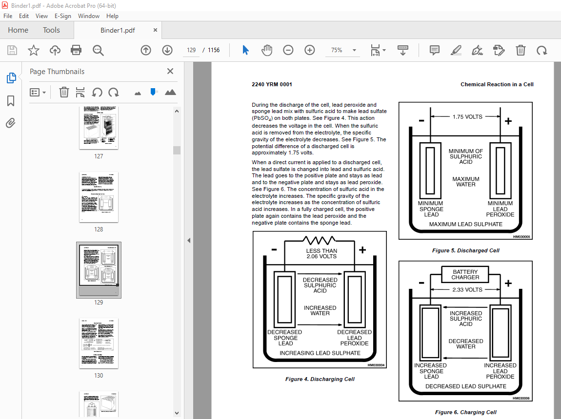
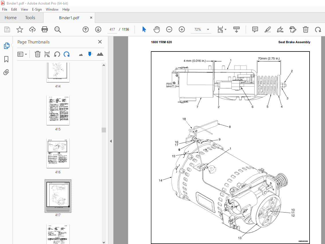
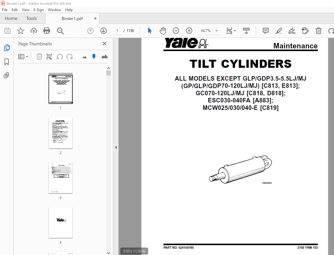
TABLE OF CONTENTS:
Yale Forklift B814 (ERC030-40AH) Service Manual – PDF DOWNLOAD
524150790-2100YRM0103-(03-2007)-UK-EN 1
toc 1
Tilt Cylinders 1
Safety Precautions Maintenance and Repair 2
General 5
Description 5
Tilt Cylinder Repair 5
Remove 5
Disassemble 5
Clean 5
Assemble 6
Tilt Cylinders With O-Ring or Single-Lip Seals 6
Tilt Cylinders 7
Install 8
Tilt Cylinder Leak Check 10
Tilt Cylinder Stroke and Mast Tilt Angle Adjustment 11
Torque Specifications 11
Piston Rod Nut 11
Retainer 11
Troubleshooting 12
tables 1
Table 1 Movement Rates (Maximum) for Tilt Cylinders 10
524150797-8000YRM0231-(02-2023)-UK-EN 17
General 23
Threaded Fasteners 23
Nomenclature, Threads 23
Strength Identification 24
Cotter (Split) Pins 25
Fastener Torque Tables 30
Conversion Table 32
524150797-8000YRM0231-(03-2020)-UK-EN 39
General 43
Threaded Fasteners 43
Nomenclature, Threads 43
Strength Identification 44
Cotter (Split) Pins 45
Fastener Torque Tables 50
Conversion Table 52
524158039-0620YRM0294-(09-2016)-UK-EN 59
General 63
Brush and Commutator Inspection 64
Hydraulic Pump Motor and Traction Motor 64
Steering Pump Motor 67
Normal Commutator Surface 67
Commutator Problems 67
Brush Replacement 72
Stoning the Commutator 75
Motors Repair 76
Disassemble 77
Traction Motor and Hydraulic Pump Motor 77
Steering Pump Motor 78
Assemble 82
Traction Motor and Hydraulic Pump Motor 82
Steering Pump Motor 84
Brush Alignment, Traction and Hydraulic Motors 86
Tests for Damaged Field and Armature 87
Test for an Open Circuit in One Armature Winding 87
Test for Short Circuit in One Armature Winding 87
Test for Short Circuit to Armature Shaft 88
Test for Open Circuit in Field Coil 88
Test for Short Circuit in Field Coil 89
Test for Short Circuit Between Field and Motor Case 89
Brush Holder Test 89
Troubleshooting 90
524158040-2240YRM0001-(01-2023)-UK-EN 95
General 101
Battery Type 101
Lead-Acid Batteries 101
Lithium-Ion Batteries 102
Specific Gravity 102
Chemical Reaction in a Cell 102
Electrical Terms 104
Battery Selection 105
Battery Voltage 106
Battery as a Counterweight 106
Battery Ratings 106
Kilowatt-Hours 106
Battery Maintenance 107
Safety Procedures 107
Maintenance Records 107
New Battery 107
Cleaning Battery 108
Adding Water to Battery 110
Hydrometer 110
Battery Temperature 111
Charging Battery 112
Types of Battery Charges 113
Methods of Charging 114
Troubleshooting Charger 115
Knowing When Battery Is Fully Charged 115
Where to Charge Batteries 115
Equipment Needed 115
Battery Connectors 116
Battery Care 116
Troubleshooting 118
524158040-2240YRM0001-(03-2020)-UK-EN 123
General 127
Battery Type 127
Lead-Acid Batteries 127
Lithium-Ion Batteries 128
Specific Gravity 128
Chemical Reaction in a Cell 128
Electrical Terms 130
Battery Selection 130
Battery Voltage 131
Battery as a Counterweight 132
Battery Ratings 132
Kilowatt-Hours 132
Battery Maintenance 132
Safety Procedures 132
Maintenance Records 133
New Battery 133
Cleaning Battery 133
Adding Water to Battery 135
Hydrometer 136
Battery Temperature 137
Charging Battery 138
Types of Battery Charges 138
Methods of Charging 140
Troubleshooting Charger 140
Knowing When Battery Is Fully Charged 141
Where to Charge Batteries 141
Equipment Needed 141
Battery Connectors 142
Battery Care 142
Troubleshooting 144
524158753-1600YRM0720-(11-2006)-UK-EN 149
toc 149
Steering Housing and Control Unit 149
Safety Precautions Maintenance and Repair 150
General 153
Description 153
Operation 154
Steering Wheel and Column Assembly Repair 155
Assembly Components, Remove 155
Steering Control Unit, Disassemble 160
Steering Control Unit, Clean 160
Steering Control Unit, Assemble 160
Assembly Components, Install 162
System Air Removal 164
Troubleshooting 164
524158890-4000YRM0521-(03-2006)-UK-EN 169
toc 169
Mast 169
Safety Precautions Maintenance and Repair 170
General 173
Description and Operation 173
Carriages 173
Mast Mounts 175
Two-Stage Mast, Limited Free-Lift (LFL) 176
Description and Operation 176
Two-Stage Mast, Full Free-Lift (FFL) 178
Description and Operation 178
Three-Stage Mast, Full Free-Lift (FFL) 180
Description and Operation 180
Four-Stage Mast 182
Description and Operation 182
Cylinder Cushion During Lifting Sequence 186
Cylinder Cushion During Lowering Sequence 187
524158891-4000YRM0522-(07-2010)-UK-EN 191
toc 191
Mast 191
Safety Precautions Maintenance and Repair 192
General 195
Safety Procedures When Working Near Mast 196
Fork Repair 198
Remove 198
Install 198
Carriages Repair 200
Standard Carriage, Remove 200
Hang-On Sideshift Carriage, Remove 201
Standard Carriage and Hang-On Sideshift Carriage, Repair 202
Standard Carriage, Install 203
Hang-On Sideshift Carriage, Install 204
Integral Sideshift Carriage 204
Remove 204
Clean and Inspect 208
Repair 209
Install 210
Mast Repair 211
Remove 211
Two-Stage LFL and Two-Stage FFL Masts, Disassemble 213
Three-Stage FFL Mast 221
Disassemble 221
Mast and Chains, Clean and Inspect 224
Two-Stage LFL and Two-Stage FFL Mast, Assemble 225
Three-Stage FFL Mast, Assemble 226
Install 227
Lift Cylinders Repair 229
Main Lift Cylinders, Remove 229
Free-Lift Cylinder, Remove 229
Cylinders, Disassemble 230
Two-Stage Full Free-Lift Mast, Right-Hand Main Lift Cylinder 230
Two-Stage Full Free-Lift Mast, Left-Hand Main Lift Cylinder 232
Two-Stage Limited Free-Lift Mast and Three-Stage Full Free-Lift 232
Two-Stage Limited Free-Lift Mast and Three-Stage Full Free-Lift 233
Two-Stage Full Free-Lift Mast and Three-Stage Full Free-Lift Mas 234
Clean and Inspect 235
Cylinders, Assemble 235
Two-Stage Full Free-Lift Mast, Right-Hand Main Lift Cylinder 235
Two-Stage Full Free-Lift Mast, Left-Hand Main Lift Cylinder 236
Two-Stage Limited Free-Lift Mast and Three-Stage Full Free-Lift 237
Two-Stage Limited Free-Lift Mast and Three-Stage Full Free-Lift 237
Two-Stage Full Free-Lift Mast and Three-Stage Full Free-Lift Mas 238
Main Lift Cylinders, Install 239
Free-Lift Cylinder, Install 239
Header Hose Arrangements 240
Two-Stage LFL Mast, New Hose Install 240
Two-Stage LFL Mast, Adjust Hoses After Installation 245
Two-Stage FFL Mast, New Hose Install 245
Two-Stage FFL Mast, Adjust Hoses After Installation 253
Three-Stage FFL Mast, New Hose Install 253
Three-Stage FFL Mast, Adjust Hoses After Installation 264
Header Hose Arrangement 265
Two-Stage LFL Mast, New Hose Install 265
Two-Stage LFL Mast, Adjust Hoses After Installation 270
Two-Stage FFL Mast, New Hose Install 270
Two-Stage FFL Mast, Adjust Hoses After Installation 276
Three-Stage FFL Mast, New Hose Install 276
Three-Stage FFL Mast, Adjust Hoses After Install 285
Lift and Tilt System Leak Check 286
Lift Cylinders Leak Check 286
Tilt Cylinders Leak Check 286
Tilt Cylinders Adjustment 287
Lift Chains Adjustment 289
Mast Adjustment 291
Carriage Adjustment 293
Troubleshooting 294
tables 191
Table 1 Hook-Type Carriage Chain Adjustment 289
Table 2 Pin-Type Carriage Chain Adjustment 290
524179936-0100YRM0617-(03-2006)-UK-EN 297
toc 297
Frame 297
Safety Precautions Maintenance and Repair 298
General 301
Description 301
Main Frame 301
Other Frame Weldments 311
Overhead Guard 312
Overhead Guard Replacement 317
Remove 317
Install 318
Battery and Operator Restraint System, Hood and Seat Brake, and 318
Battery Restraint System 318
Hood and Seat Brake 320
Hood With E-Hydraulics 321
Operator Restraint System and Seat Assembly 322
Automatic Locking Retractor (ALR) 322
Emergency Locking Retractor (ELR) 322
Counterweight Replacement 323
Remove 323
Install 325
Traction Motor Replacement 326
Remove 326
Install 328
Hydraulic Tank Repair 329
Inspect 329
Clean 330
Steam Method 330
Chemical Solution Method 330
Additional Preparations for Repair 331
Small Leaks, Repair 331
Large Leaks, Repair 331
Preparations for Usage After Repair 331
Painting Instructions 331
Safety Label Replacement 333
Battery Specifications 335
tables 297
Table 1 Counterweights 324
524179939-1400YRM0618-(03-2006)-UK-EN 339
toc 339
Drive Axle, Speed Reducer, and Differential 339
Safety Precautions Maintenance and Repair 340
General 343
Description 343
Drive Unit Assembly Repair 343
Remove Complete Drive Unit Assembly as a Unit 343
Traction Motor, Remove 344
Drive Unit and Speed Reducer, Remove 346
Drive Axle, Disassemble 347
Differential and Speed Reducer, Disassemble 347
Clean 350
Inspect 350
Assembly of Drive Unit 350
Find Correct Shim Set for Hypoid Gear 350
Pinion, Assemble and Install 351
Differential and Ring Gear, Assemble and Install 352
Input Gear for Speed Reducer, Assemble 356
Drive Axle and Hub Assembly, Assemble 357
Installation of Drive Unit 358
Drive Unit, Install 358
Traction Motor, Install 359
Torque Specifications 360
Troubleshooting 361
tables 339
Table 1 Shims Adjustment for Pinion 351
Table 2 Ring and Pinion Tooth Contact Adjustment 355
524179940-1600YRM0619-(03-2006)-UK-EN 365
toc 365
Steering Axle 365
Safety Precautions Maintenance and Repair 366
General 369
Description 369
Steering Axle Assembly Repair 370
Remove 370
Install 370
Wheels and Hubs Repair 371
Remove and Disassemble 371
Clean 371
Assemble and Install 371
Spindles, Bearings, and Links Repair 375
Remove and Disassemble; Lift Truck Models ERC/P16-20AAF (A814/B8 375
Clean 375
Assemble and Install; Lift Truck Models ERC/P16-20AAF (A814/B814 375
Remove and Disassemble; Lift Truck Models ERC030-040AF and ERC03 377
Clean 377
Inspect 377
Assemble and Install; Lift Truck Models ERC030-040AF and ERC030- 377
Steering Cylinder Repair 379
Remove and Disassemble 379
Clean and Inspect 379
Assemble and Install 379
Torque Specifications 380
Troubleshooting 381
524179944-1800YRM0620-(03-2008)-UK-EN 385
toc 385
Brake System 385
Safety Precautions Maintenance and Repair 386
General 389
Description and Operation 389
Service Brakes 389
Master Cylinder 389
Parking Brake 391
Service Brakes Repair 391
Remove and Disassemble 391
Clean 394
Inspect 394
Assemble and Install 395
Master Cylinder Repair 398
Remove 398
Disassemble 399
Clean and Inspect 401
Assemble 401
Install 404
Parking Brake Repair 404
Remove and Dissemble 404
Assemble and Install 404
Parking Brake Switch Replacement 408
Brake System Air Removal 408
Service Brakes Adjustment 409
Brake Pedal Adjustment 409
Master Cylinder Adjustment 410
Parking Brake Adjustment 410
Parking Brake Switch Adjustment 410
Parking Brake Not Applied Switch Test 410
Seat Brake Assembly 410
Seat Brake, Adjust – Lift Truck Models ERC/P16-20AAF (ERC030-040 410
Brake Switch, Adjust – Lift Truck Models ERC/P16-20AAF (ERC030-0 411
Electric Seat Brake Without Handle, Adjust for Lift Truck Model 412
Electric Seat Brake With Handle for Lift Truck Model ERC/P16-20A 413
Remove 413
Clean 413
Inspect 413
Install 415
Adjustments 415
Solenoid Adjustment 415
Traction cutoff Switch Adjustment 415
Cable Adjustment 416
Torque Specifications 418
Troubleshooting 418
524179945-1900YRM0559-(04-2009)-UK-EN 425
toc 425
Hydraulic System 425
Safety Precautions Maintenance and Repair 426
General 429
Description 429
Hydraulic System 429
Operation 437
Hydraulic System 437
Hydraulic Gear Pump 443
Steering Pump 443
Hydraulic Tank Repair 451
Tank, Remove [ERC/P16-20AAF (ERC030-040AF, AG/BG) (A814); ERC/P1 451
Tank, Remove [ERP20-30ALF (B216) and ERP20-30ALF (ERP040-060DH) 453
Tank, Remove [ERP20-32ALF (ERP040-065DH) (E216)] 454
Hydraulic Tank [ERC35-55HG (ERC70-120HH) (B839/C839)] 454
Inspect 455
Small Leaks, Repair 456
Large Leaks, Repair 456
Clean 456
Steam Method 456
Chemical Solution Method 457
Additional Methods for Tank Repair 457
Tank, Install [ERC/P16-20AAF (ERC030-040AF, AG/BG) (A814); ERC/P 457
Tank, Install [ERP20-30ALF (B216) and ERP20-30ALF (ERP040-060DH) 458
Tank, Install [ERP20-32ALF (ERP040-065DH) (E216)] 458
Filter Replacement 459
All Lift Trucks Except [ERC35-55HG (ERC70-120HH) (B839/C839); ER 459
Remove 459
Install 460
Lift Truck Models [ERC35-55HG (ERC70-120HH) (B839/C839)] 460
Remove 460
Install 460
Lift truck Models [ERC20-32AGF (ERC040-065GH) (A908) and ERC/P16 461
Remove 461
Install 461
Lift Truck Models [ERP20-32ALF (ERP040-065DH) (E216)] 463
Remove 463
Install 463
Hydraulic Pump Repair 466
Hydraulic Pump, Remove [ERC/P16-20AAF (ERC030-040AF, AG/BG) (A81 466
Hydraulic Pump, Disassemble ERC/P16-20AAF (ERC030-040AF, AG/BG) 466
Inspect 468
Clean 468
Pump Seal Replace and Pump Assemble 468
Assemble Pump on Motor 468
Hydraulic Pump and Motor, Install [ERC/P16-20AAF (ERC030-040AF, 470
Hydraulic Pump, Remove [ERP20-30ALF (B216); ERP20-30ALF (ERP040- 471
Hydraulic Pump, Disassemble [ERC35-55HG (ERC70-120HH) (B839/C839 472
Hydraulic Pump, Inspect [ERC35-55HG (ERC70-120HH) (B839/C839) an 474
Hydraulic Pump, Clean [ERC35-55HG (ERC70-120HH) (B839/C839) and 474
Hydraulic Pump, Assemble [ERC35-55HG (ERC70-120HH) (B839/C839) a 474
Hydraulic Pump and Motor, Install [ERP20-30ALF (B216); ERP20-30A 474
Main Control Valve Repair 476
Steering Pump Repair 476
Pump, Remove and Disassemble [ERC/P16-20AAF (ERC030-040AF, ERC03 476
Pump, Remove and Disassemble [ERP20-30ALF (B216); ERP20-30ALF (E 478
Pump, Assemble and Install 480
Steering Control Unit Replacement 481
Remove 481
Install 481
Steering Cylinder Repair 487
Main Control Valve Check and Adjust 487
Steering Relief Valve Check and Adjust 488
Specifications 488
Relief Valve Pressures* 488
Hydraulic Tank Capacity (dipstick full mark) 489
Hydraulic Pump Capacities – All Models Except ERC35-55HG (ERC70- 489
Hydraulic Pump Capacities – Models ERC35-55HG (ERC70-120HH) (B83 489
Troubleshooting 489
Steering 489
Steering Housing and Steering Control Unit 490
Hydraulic System 491
524179946-2000YRM0562-(02-2009)-UK-EN 497
toc 497
Manual hydraulic Control Valve 497
Safety Precautions Maintenance and Repair 498
General 501
Description 501
Operation 504
ERC/P16-20AAF (ERC030-040AF, AG/BG) (A814); ERC/P16-20AAF (ERC03 504
ERP20-30ALF (B216), ERP20-30ALF (ERP040-060DH) (D216) and ERP20- 504
Lift Section 506
Tilt Section 506
Tilt Backward 506
Tilt Forward 506
Relief Valve 508
Main Control Valve Repair 509
Main Control Valve Without OPS Solenoid 509
Remove 509
Disassemble 509
Clean and Inspect 513
Assemble 513
Install [ERC/P16-20AAF (ERC030-040AF, AG/BG) (A814); ERC/P16-20A 514
Install [ERP20-30ALF (B216), ERP20-30ALF (ERP040-060DH) (D216) a 514
Main Control Valve With OPS Solenoid 515
Remove 515
Disassemble 515
Clean and Inspect 517
Relief Valve Repair 519
Assemble 520
Install 521
Control Lever Linkage Repair 521
Remove [ERC/P16-20AAF (ERC030-040AF, AG/BG) (A814),ERC/P16-20AAF 521
Disassemble [ERC/P16-20AAF (ERC030-040AF, AG/BG) (A814),ERC/P16- 521
Assemble and Install [ERC/P16-20AAF (ERC030-040AF, AG/BG) (A814) 523
Control Valve Linkage Repair 523
Remove and Disassemble [ERC/P16-20AAF (ERC030-040AF, AG/BG) (A81 523
Assemble and Install [ERC/P16-20AAF (ERC030-040AF, AG/BG) (A814) 524
Control Lever Linkage Repair 524
Remove [ERP20-30ALF (B216), ERP20-30ALF (ERP040-060DH) (D216) an 524
Disassemble [ERP20-30ALF (B216), ERP20-30ALF (ERP040-060DH) (D21 526
Assemble and Install [ERP20-30ALF (B216), ERP20-30ALF (ERP040-06 526
Pressure Relief Valve Check and Adjustment 527
Primary Relief Valve 527
Secondary Relief Valve 528
Troubleshooting 529
524183081-1600YRM1054-(11-2006)-UK-EN 533
toc 533
Steering System for AC Electric Lift Trucks 533
Safety Precautions Maintenance and Repair 534
General 537
Description 538
Steering Wheel and Column Assembly Repair 539
General 539
Assembly Components, Remove 541
Assembly Components, Install 542
Power Steering Motor and Pump 543
Description 543
Remove 543
Disassemble 546
Install 546
Power Steering Pump, Repair 546
Seal, Replace 547
Steering System Air Removal 548
Steering Pressure Check 548
Steering Motor Circuits Check 549
Troubleshooting 550
524183082-2200YRM1055-(10-2009)-UK-EN 555
toc 555
Electrical System (Trucks With AC Controllers) 555
Safety Precautions Maintenance and Repair 556
General 559
Description 560
Features of the Display Panels 560
Other Control Components 561
Display Panel and Key Switch Replacement 562
Display Panel, Replace 562
Key Switch, Replace 564
Controller Replacement 564
Traction and Pump Motor Controller Replacement 564
Master Controller, Replace 570
Master Controller, Remove ERP20-30ALF (ERP040-060DH) (D216), ERP 570
Master Controller, Install ERP20-30ALF (ERP040-060DH) (D216), ER 570
Master Controller, Remove ERC/P16-20AAF (ERC030-040AH) (B814/C81 572
Master Controller, Install ERC/P16-20AAF (ERC030-040AH) (B814/C8 572
Master Controller, Remove ERC35-55HG (ERC070-120HH) (B839/C839) 574
Master Controller, Install ERC35-55HG (ERC070-120HH) (B839/C839) 574
Control Components Replacement 575
General 575
Start Switch, Replace 575
Brake Light Switch, Replace 576
Seat Switch, Replace 576
Parking Brake Switch, Replace 577
Foot Directional Control Pedal Direction Switches, Replace 579
Steering Column Direction Control Switches, Replace 582
Remove 582
Install 582
Brake Fluid Switch, Replace 584
Brush Wear and Over Temperature Sensors (DC Pump Motor Only) 584
Rocker Switches for Lights, Replace 584
Accelerator Position Sensor, Replace 585
On-Demand Steering Sensor, Replace 586
Lights, Converter, Relay, and Reverse Alarm 586
Brake, Tail, and Reverse Light Assembly, Replace 587
Incandescent Assembly 587
LED Assembly – Remove 589
LED Assembly – Install 589
Strobe Light Assembly, Replace 592
Wire Harness Repair 593
Del-City Crimp-Solder-Shrink Splice 593
Front, Rear Driving Light or Spot Light Assemblies, Replace 594
Converter, Replace 594
Remove, Lift Truck Models ERP20-30ALF (ERP040-060DH) (D216), ERP 594
Install, Lift Truck Models ERP20-30ALF (ERP040-060DH) (D216), ER 596
Remove, Lift Truck Models ERC20-32AGF (ERC040-065GH) (A908) and 596
Install, Lift Truck Models ERC20-32AGF (ERC040-065GH) (A908) and 596
Remove, Lift Truck Models ERC35-55HG (ERC70-120HH) (B839/C839) 598
Install, Lift Truck Models ERC35-55HG (ERC70-120HH) (B839/C839) 598
Reverse Relay, Replace 599
Lift Truck Models ERC20-32AGF (ERC040-065GH) (A908), ERC/P16-20A 599
Lift Truck Models ERC35-55HG (ERC70-120HH) (B839/C839) 599
Backup Alarm, Replace 601
Horn and Horn Button, Replace 601
Horn Replacement for Lift Trucks ERP20-30ALF (ERP040-060DH) (D21 601
Horn Replacement for Lift Trucks ERC35-55HG (ERC70-120HH) (B839/ 603
Horn Switch and Cover, Replace 604
Hydraulic Pump Switches 605
Fan Power Supply, Replace 605
Remove, Lift Truck Models ERC35-55HG (ERC70-120HH) (B839/C839) 605
Install, Lift Truck Models ERC35-55HG (ERC70-120HH) (B839/C839) 605
Remove, Lift Truck Models ERP20-30ALF (ERP040-060DH) (D216) and 606
Install, Lift Truck Models ERP20-30ALF (ERP040-060DH) (D216) and 607
Remove, Lift Truck Models ERC20-32AGF (ERC040-065GH) (A908) 607
Install, Lift Truck Models ERC20-32AGF (ERC040-065GH) (A908) 607
Control and Power Fuse Check 608
Fuse Locations 608
Brake Light Switch Adjustment 614
Seat Switch Check 615
Seat Brake Adjustment 615
Parking Brake Switch Adjustment 616
Direction Switches Check 616
Foot Directional Control Pedal 616
Steering Column 617
Foot Directional Control Pedal or Accelerator Pedal Adjustment 617
Accelerator Position Sensor Adjustment and Start Switch Adjustme 618
Acceleration Position Sensor, Adjust 618
Start Switch, Adjust 620
tables 555
Table 1 Wire Splice Size 593
524183083-2200YRM1056-(03-2009)-UK-EN 623
toc 623
AC Motor Controllers/Display Panel 623
Safety Precautions Maintenance and Repair 624
Description 627
General 627
AC Motors 627
Motor Controllers 627
Master Controller 627
Dash Display 627
Controller Area Network Bus (CANbus) 627
Master Controller Checks and Adjustments 628
Function Settings 629
General 629
Function Numbers 629
Function Descriptions 632
General 632
Function Number 1 BATTERY VOLTAGE 632
Function Number 2 EXTENDED SHIFT 632
Function Number 3 ACCELERATION 1 632
Function Number 4 ACCELERATION 2 632
Function Number 5 TOP SPEED LIMIT 632
Function Number 6 REGEN BRAKING 632
Function Number 7 AUTO DECELERATION 633
Function Number 8 BDI ADJUSTMENT 633
Function Number 9 LIFT INTERRUPT 633
Function Number 10 POWER STEERING TIME DELAY 633
Function Number 11 SERVICE REMINDER 633
Function Number 12 CUSTOM 633
Function Number 13 PUMP SPEED 1 633
Function Number 14 PUMP SPEED 2 634
Function Number 15 PUMP SPEED 3 634
Function Number 16 PUMP ACCELERATION 634
Troubleshooting 634
General 634
Controller Status Light Emitting Diodes (LEDs) 635
Master Controller 635
AC Motor Controllers 635
Status Codes 641
AC Motor Controllers Status Code Charts 643
Troubleshooting When Dash and/or Lift Truck is not Operational 664
Typical Symptoms 664
Truck Runs but Dash Display is not Operational, or Only Displays 664
Truck Does Not Run and Dash is Not Operational or Only Displays 665
Hydraulics Operate Normally, Traction Does Not Operate Correctly 666
Traction Operates Normally, Hydraulics do Not Operate Correctly, 666
AC Transistor Motor Controller Replacement 666
General 666
General Maintenance Instructions 672
Special Precautions 672
Fuses 673
Fan Test 673
Contactors 673
Repair 673
Thermal Sensors 677
Motor Controller, Replace 677
Display Panel 678
General 678
Premium Display Panel 678
Standard Display Panel 678
Display Functions and Features 679
Key-On Initialization 679
Standard Display 680
Premium Display 680
Lift Truck Inspection Function 681
Access to Service Functions 681
Service Functions 681
Service Functions 682
Performance Modes 684
Battery Discharge Indicator (BDI) 684
Hourmeter 685
Dash Display Service Menu Navigation 691
General 691
Moving Through Menu Selections 691
Editing and Adding Information 691
tables 623
Table 1 Factory Parameters for ERP20-30ALF (ERP040-060DH) (D216 629
Table 2 Factory Setting for ERC020-032AGF (ERC40-65GH) (A908) 630
Table 3 Factory Setting for ERC/P16-20AAF (ERC030-040AH) (B814/ 630
Table 4 Factory Parameters for ERC35-55HG (ERC70-120HH) (B839/C 631
Table 5 List of Status Codes 641
Table 6 42-Pin Connections/Descriptions for Master Controller 674
Table 7 Pin Connections/Descriptions for 72/80 (Gen IV) Volt Mo 676
Table 8 Pin Connections/Descriptions for 36/48 and 72v/80v (Gen 676
524183085-2200YRM1058-(04-2011)-UK-EN 695
toc 695
Troubleshooting and Adjustments Using the AC Controls Program (E 695
Safety Precautions Maintenance and Repair 696
General 699
Computer Requirements 699
Software, Install 699
Language Selection 699
Demo Mode 700
Connect PC to Lift Truck 704
Starting AC Controls Program 706
Lift Truck Control Setup 711
Change Lift Truck Serial Number or Hourmeter 711
Setting Factory Default Values or Changing Lift Truck Parameters 712
Create New Custom Lift Truck Configuration 718
Lift Truck Configuration Properties 721
Import New Lift Truck Configuration From Disk 724
Delete Custom Lift Truck Configuration or Password File 726
Dash Display 729
Custom Display Languages 729
Download Display Language 731
Clear Operator Log 731
Password Functions 734
Enable/Disable Password and Lift Truck Inspection Functions 734
Truck Inspection Checklist 734
Password 734
Password Properties 734
Create New Password File 739
Download Passwords 740
Upload Passwords 742
Reports Menu 744
Devices Report 744
Custom Report 744
Password Report 744
Operator Report 751
Current Settings Report 754
Status Code Report 758
Status Codes Log 761
Troubleshooting 763
Diagnostics 763
Help Menu 766
General 766
Contents 766
Technical Support 766
About Electric Truck AC Controls Program 766
524183086-8000YRM1059-(08-2012)-UK-EN 773
toc 773
Electrical Diagrams 773
Safety Precautions Maintenance and Repair 774
524183087-8000YRM1060-(02-2010)-UK-EN 849
toc 849
Periodic Maintenance 849
Safety Precautions Maintenance and Repair 850
General 855
Serial Number Data 855
How to Move Disabled Lift Truck 855
How to Tow Lift Truck 855
How to Put Lift Truck on Blocks 856
How to Raise Drive Tires 856
How to Raise Steering Tires 856
How to Clean a Lift Truck 856
Maintenance Schedule 858
Maintenance Procedures Every 8 Hours or Daily 865
How to Make Checks With Key OFF 865
Tires and Wheels 865
Forks 866
Inspect 866
Mast and Lift Chains, Inspect 867
Safety Labels 867
Steering Column Latch 867
Operator Restraint System 868
Automatic Locking Retractor (ALR) 868
Emergency Locking Retractor (ELR) 868
Battery Restraint System ERC20-32AGF (ERC040-065GH) (A908) and E 869
Battery Restraint System ERP20-30ALF (ERP040-060DH) (D216) Lift 870
Battery 870
Attachment 871
Hydraulic System 871
How to Make Checks With Key ON 872
Horn, Lights, and Alarm 872
Steering System 872
Service Brakes 872
Parking Brake 872
Control Levers and Pedals 873
Direction and Speed Control Pedals 873
Lift System Operation 873
Oil Leaks 873
First Service After First 100 Hours of Operation 873
Change Filter for Hydraulic Oil 873
Maintenance Procedures Every 250 Hours or 6 Weeks 875
Steering King Pins ERC/P16-20AAF (B814/C814) Trucks Only 875
Steering Tie Rods and Spindles 875
Maintenance Procedures Every 500 Hours or 3 Months 875
Differential and Speed Reducer ERC20-32AGF (ERC040-065GH) (A908) 875
Wheel Nut Torques 876
Header Hose Checks 876
Mast Lubrication 876
Forks 880
Remove 880
Inspect 880
Install 880
Adjust 881
Brake Fluid ERC/P16-20AAF (ERC030-040AH) (B814/C814) and ERC20-3 881
Parking Brake Adjustment 881
Seat Brake Operations Check 882
Maintenance Procedures Every 1000 Hours or 6 Months 882
Lift Chains 882
Wear Check 882
Lift Chain Lubrication 883
Forks 883
Check Upper and Lower Bearings, Integral Sideshift Carriage 883
Steering King Pins ERC20-32AGF (ERC040-065GH) (A908) Lift Truck 884
Steering Tie Rods ERP20-30ALF (ERP040-060DH) (D216) Lift Truck M 884
Steering Axle Spindles 884
King Pins ERP20-30ALF (ERP040-060DH) (D216) 884
Hydraulic Tank Breather 884
ERP20-30ALF (ERP040-060DH) (D216) 884
ERC20-32AGF (ERC040-065GH) (A908) 885
ERC/P16-20AAF (ERC030-040AH) (B814/C814) 885
Differential and Speed Reducer ERP20-30ALF (ERP040-060DH) (D216) 885
Brake Fluid ERP20-30ALF (ERP040-060DH) (D216) Lift Truck Models 886
Other Lubrication 886
Electrical Inspection 886
Contactors 886
Motor Brushes (DC Pump) 886
Motor Brushes, General 886
Maintenance Procedures Every 2000 Hours or Yearly 890
Hydraulic System 890
Change Filter for Hydraulic Oil 890
Change Hydraulic Oil 891
Differential and Speed Reducer 891
Brake Fluid Replacement 892
Service Brakes 892
Steering Tie Rods and Spindle Lift Truck Models ERC030-040AH (B8 892
Wheel Bearings 893
Steer Wheels, Lubrication 893
Drive Wheels, Lubrication 893
Lift Chains 893
Forks 893
Replace Upper and Lower Bearings, Integral Sideshift Carriage 893
Other Lubrication 893
Battery Maintenance 894
How to Charge Battery 894
How to Change Battery for ERP20-30ALF (ERP040-060DH) (D216) and 895
General 895
How to Change Battery for ERC20-32AGF (ERC040-065GH) (A908) and 897
General 897
Lift and Tilt System Leak Check 900
Lift Cylinders Leak Check 900
Tilt Cylinders Leak Check 901
Safety Procedures When Working Near Mast 901
WHEN WORKING NEAR THE MAST ALWAYS: 901
Lift Chain Adjustments 904
Welding Repairs 905
Overhead Guard Changes 905
Wheels and Tire Maintenance 906
Solid Rubber Tires ERC20-32AGF (ERC040-065GH) (A908) and ERC/P16 906
Remove Wheels From Lift Truck 906
Remove and Install Tire on Wheel 906
Pneumatic Tires and Wheels ERP20-30ALF (ERP040-060DH) (D216) 907
Remove Wheels From Lift Truck 907
Remove Wheel From Pneumatic Tire 908
Install Three- or Four-Piece Wheel in Pneumatic Tire 909
Add Air to Tires 910
Wheels, Install 910
Solid Rubber Tires on Pneumatic Wheels 911
Remove Wheels From Lift Truck 911
Remove Solid Rubber Tire From Pneumatic Wheel 911
Install Solid Rubber Tire on Pneumatic Wheel 913
Wheels, Install 914
Snap-On Tire, Change 914
Remove Snap-On Solid Tire From Wheel 915
Install Snap-On Solid Tire on Wheel 916
Adhesives and Sealants 917
tables 849
Table 1 Maintenance Schedule 860
524205680-0620YRM1098-(03-2010)-UK-EN 921
toc 921
AC Motor Repair 921
Safety Precautions Maintenance and Repair 922
General 925
AC Motor Repair 925
Disassemble 925
Assemble 929
Troubleshooting 931
524213865-8000YRM1113-(02-2009)-UK-EN 935
toc 935
Capacities and Specifications 935
Safety Precautions Maintenance and Repair 936
Wheels and Tires 939
Counterweights 939
Hydraulic System 939
Capacities 940
Battery Specifications 941
Battery Height Specifications (Hoods and Battery Types) 942
Maximum Carriage and Tilt Creep Rates 943
Mast Speeds 943
ERC030AH, ERC040AH, Mast Speeds (36 and 48 Volt) Americas 943
ERC/P16-20AAF Mast Speeds (48 Volt) Europe 944
Torque Specifications 945
Frame 945
Mast 945
Drive Axle, Speed Reducer, and Differential 946
Steering Axle 946
Brake 946
E-Hydraulic Control Valve 946
Adhesives and Sealants 947
tables 935
Table 1 Manual Control Valve 939
Table 2 E-Hydraulic Control Valve 940
524223768-2100YRM1139-(02-2014)-UK-EN 951
524223776-4000YRM1148-(09-2015)-UK-EN 999
General 1003
Safety Procedures When Working Near Mast 1004
Fork Replacement 1006
Remove, Lift Trucks Not Equipped With Fork Positioner Or Equipped With Fork Positioner Before August, 2012 1006
Remove, Lift Trucks Manufactured After August, 2012 And Equipped With Fork Positioner 1008
Install, Lift Trucks Not Equipped With Fork Positioner Or Equipped With Fork Positioner Before August, 2012 1009
Install, Lift Trucks Manufactured After August, 2012 And Equipped With Fork Positioner 1009
Checks, Lift Trucks Not Equipped With Fork Positioner Or Equipped With Fork Positioner Before August, 2012 1010
Checks, Lift Trucks Manufactured After August, 2012 And Equipped With Fork Positioner 1011
Carriages Repair 1012
Standard Carriage 1012
Remove 1012
Repair 1013
Install 1013
Standard Carriage, Remove 1014
Hang-On Sideshift Carriage, Remove 1015
Standard Carriage and Hang-On Sideshift Carriage, Repair 1016
Standard Carriage, Install 1017
Hang-On Sideshift Carriage, Install 1017
Integral Sideshift Carriage 1018
Remove 1018
Clean and Inspect 1021
Repair 1022
Install 1022
Fork Positioner 1023
Remove 1023
Clean and Inspect 1028
Disassemble and Assemble 1028
Install 1028
Fork Positioner Hydraulic Hose Adjustment 1029
Disconnecting Attachment Hydraulic Quick Disconnect Hoses 1031
Connecting Attachment Hydraulic Quick Disconnect Hoses 1031
Mast Repair 1032
Mast, Remove 1032
Two-Stage LFL and Two-Stage FFL Masts 1035
Disassemble 1035
Clean and Inspect 1045
Three-Stage FFL Mast 1046
Disassemble 1046
Clean and Inspect 1054
Two-Stage LFL and Two-Stage FFL Mast 1056
Assemble 1056
Three-Stage FFL Mast 1059
Assemble 1059
Four-Stage FFL Mast – Manufactured Before July, 2009 1061
Disassemble 1061
Clean and Inspect 1066
Assemble 1068
Four-Stage FFL Mast – Manufactured After July, 2009 1069
Disassemble 1069
Clean and Inspect 1076
Assemble 1079
Mast, Install 1080
Header Hose Arrangement 1083
Two-Stage LFL 1083
Two-Stage FFL 1091
Three-Stage FFL 1106
Standard 1106
Optional Equipment Lift Truck GLP/GDP20-35VX (GP/GLP/GDP040-070VX) (B875) 1123
Four-Stage FFL Mast – Manufactured Before July, 2009 1131
Four-Stage FFL Mast – Manufactured After July, 2009 1140
Adjustment 1147
Lift Chains Adjustment 1147
Carriage Adjustments 1150
Mast Adjustments 1150
Load Roller Adjustment 1150
Mast Side Kicking Adjustment 1153
More products