$45.95
Yale Forklift B814 (ERC16-20AAF, ERP16-20AAF) Service Manual PDF
Yale Forklift B814 (ERC16-20AAF, ERP16-20AAF) Service Manual – PDF DOWNLOAD
FILE DETAILS:
Yale Forklift B814 (ERC16-20AAF, ERP16-20AAF) Service Manual – PDF DOWNLOAD
Language : English
Pages : 1974
Downloadable : Yes
File Type : PDF
IMAGES PREVIEW OF THE MANUAL:
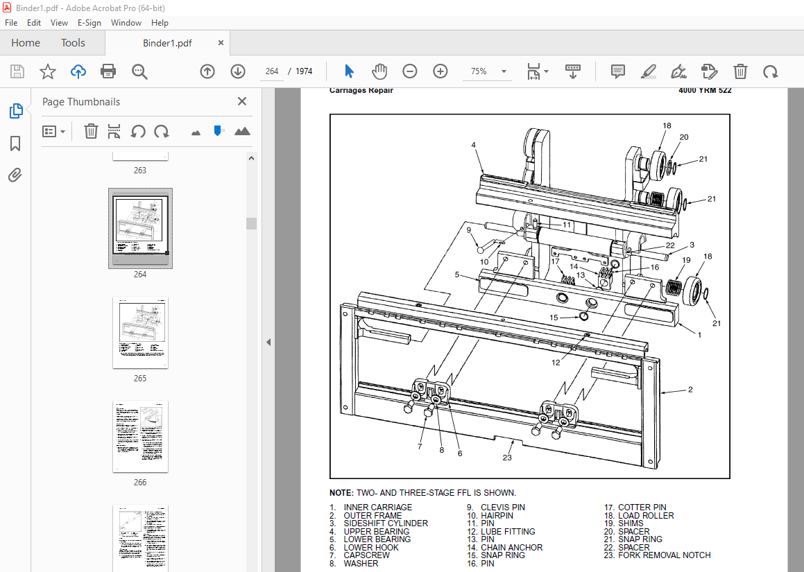
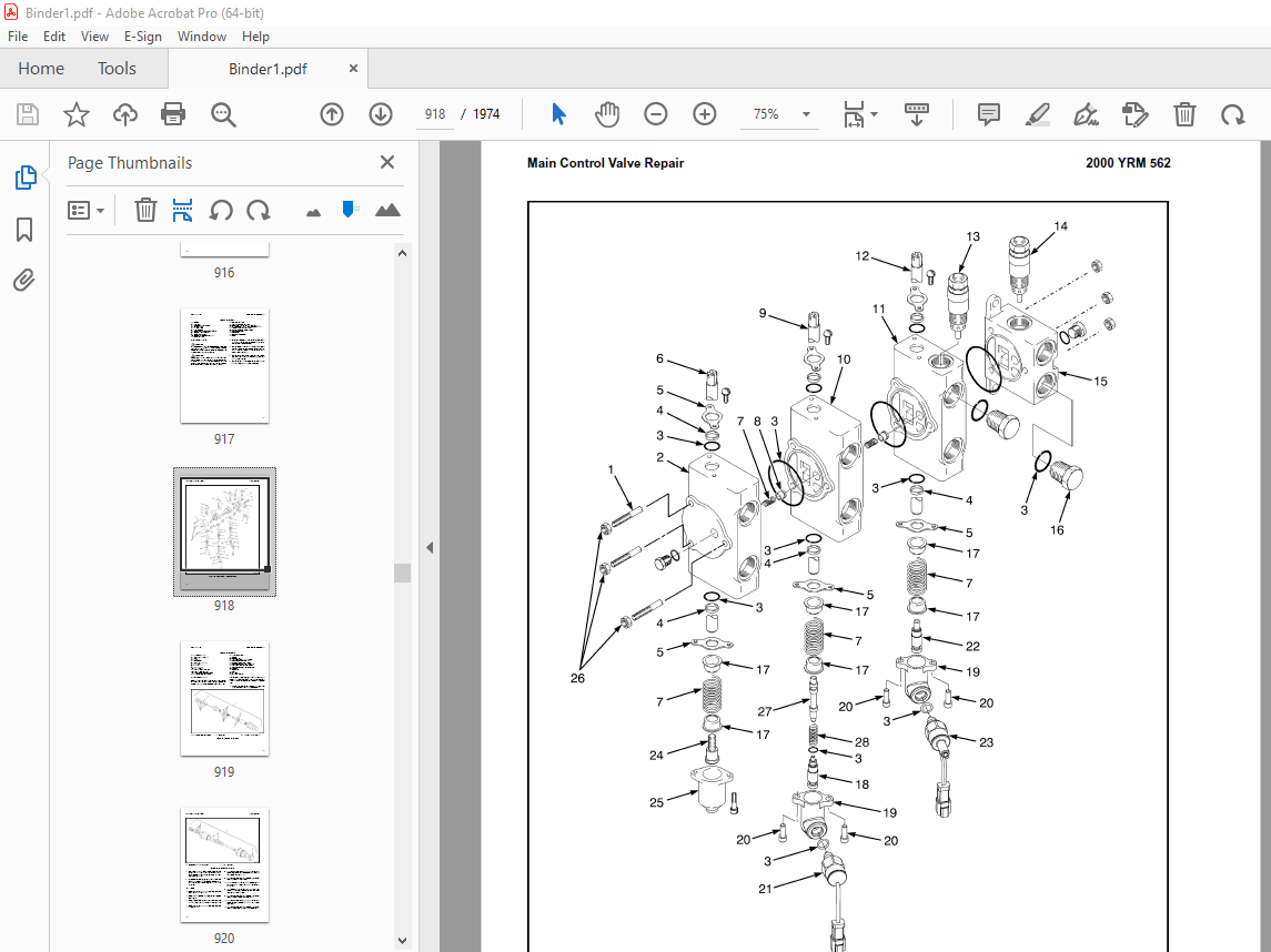
TABLE OF CONTENTS:
Yale Forklift B814 (ERC16-20AAF, ERP16-20AAF) Service Manual – PDF DOWNLOAD
524150790-2100YRM0103-(03-2007)-UK-EN (2) 1
toc 1
Tilt Cylinders 1
Safety Precautions Maintenance and Repair 2
General 5
Description 5
Tilt Cylinder Repair 5
Remove 5
Disassemble 5
Clean 5
Assemble 6
Tilt Cylinders With O-Ring or Single-Lip Seals 6
Tilt Cylinders 7
Install 8
Tilt Cylinder Leak Check 10
Tilt Cylinder Stroke and Mast Tilt Angle Adjustment 11
Torque Specifications 11
Piston Rod Nut 11
Retainer 11
Troubleshooting 12
tables 1
Table 1 Movement Rates (Maximum) for Tilt Cylinders 10
524150790-2100YRM0103-(03-2007)-UK-EN 17
toc 17
Tilt Cylinders 17
Safety Precautions Maintenance and Repair 18
General 21
Description 21
Tilt Cylinder Repair 21
Remove 21
Disassemble 21
Clean 21
Assemble 22
Tilt Cylinders With O-Ring or Single-Lip Seals 22
Tilt Cylinders 23
Install 24
Tilt Cylinder Leak Check 26
Tilt Cylinder Stroke and Mast Tilt Angle Adjustment 27
Torque Specifications 27
Piston Rod Nut 27
Retainer 27
Troubleshooting 28
tables 17
Table 1 Movement Rates (Maximum) for Tilt Cylinders 26
524150797-8000YRM0231-(02-2023)-UK-EN 33
General 39
Threaded Fasteners 39
Nomenclature, Threads 39
Strength Identification 40
Cotter (Split) Pins 41
Fastener Torque Tables 46
Conversion Table 48
524150797-8000YRM0231-(03-2020)-UK-EN 55
General 59
Threaded Fasteners 59
Nomenclature, Threads 59
Strength Identification 60
Cotter (Split) Pins 61
Fastener Torque Tables 66
Conversion Table 68
524158039-0620YRM0294-(09-2016)-UK-EN 75
General 79
Brush and Commutator Inspection 80
Hydraulic Pump Motor and Traction Motor 80
Steering Pump Motor 83
Normal Commutator Surface 83
Commutator Problems 83
Brush Replacement 88
Stoning the Commutator 91
Motors Repair 92
Disassemble 93
Traction Motor and Hydraulic Pump Motor 93
Steering Pump Motor 94
Assemble 98
Traction Motor and Hydraulic Pump Motor 98
Steering Pump Motor 100
Brush Alignment, Traction and Hydraulic Motors 102
Tests for Damaged Field and Armature 103
Test for an Open Circuit in One Armature Winding 103
Test for Short Circuit in One Armature Winding 103
Test for Short Circuit to Armature Shaft 104
Test for Open Circuit in Field Coil 104
Test for Short Circuit in Field Coil 105
Test for Short Circuit Between Field and Motor Case 105
Brush Holder Test 105
Troubleshooting 106
524158040-2240YRM0001-(01-2023)-UK-EN 111
General 117
Battery Type 117
Lead-Acid Batteries 117
Lithium-Ion Batteries 118
Specific Gravity 118
Chemical Reaction in a Cell 118
Electrical Terms 120
Battery Selection 121
Battery Voltage 122
Battery as a Counterweight 122
Battery Ratings 122
Kilowatt-Hours 122
Battery Maintenance 123
Safety Procedures 123
Maintenance Records 123
New Battery 123
Cleaning Battery 124
Adding Water to Battery 126
Hydrometer 126
Battery Temperature 127
Charging Battery 128
Types of Battery Charges 129
Methods of Charging 130
Troubleshooting Charger 131
Knowing When Battery Is Fully Charged 131
Where to Charge Batteries 131
Equipment Needed 131
Battery Connectors 132
Battery Care 132
Troubleshooting 134
524158040-2240YRM0001-(03-2020)-UK-EN 139
General 143
Battery Type 143
Lead-Acid Batteries 143
Lithium-Ion Batteries 144
Specific Gravity 144
Chemical Reaction in a Cell 144
Electrical Terms 146
Battery Selection 146
Battery Voltage 147
Battery as a Counterweight 148
Battery Ratings 148
Kilowatt-Hours 148
Battery Maintenance 148
Safety Procedures 148
Maintenance Records 149
New Battery 149
Cleaning Battery 149
Adding Water to Battery 151
Hydrometer 152
Battery Temperature 153
Charging Battery 154
Types of Battery Charges 154
Methods of Charging 156
Troubleshooting Charger 156
Knowing When Battery Is Fully Charged 157
Where to Charge Batteries 157
Equipment Needed 157
Battery Connectors 158
Battery Care 158
Troubleshooting 160
524158753-1600YRM0720-(11-2006)-UK-EN (2) 165
toc 165
Steering Housing and Control Unit 165
Safety Precautions Maintenance and Repair 166
General 169
Description 169
Operation 170
Steering Wheel and Column Assembly Repair 171
Assembly Components, Remove 171
Steering Control Unit, Disassemble 176
Steering Control Unit, Clean 176
Steering Control Unit, Assemble 176
Assembly Components, Install 178
System Air Removal 180
Troubleshooting 180
524158753-1600YRM0720-(11-2006)-UK-EN 185
toc 185
Steering Housing and Control Unit 185
Safety Precautions Maintenance and Repair 186
General 189
Description 189
Operation 190
Steering Wheel and Column Assembly Repair 191
Assembly Components, Remove 191
Steering Control Unit, Disassemble 196
Steering Control Unit, Clean 196
Steering Control Unit, Assemble 196
Assembly Components, Install 198
System Air Removal 200
Troubleshooting 200
524158890-4000YRM0521-(03-2006)-UK-EN (2) 205
toc 205
Mast 205
Safety Precautions Maintenance and Repair 206
General 209
Description and Operation 209
Carriages 209
Mast Mounts 211
Two-Stage Mast, Limited Free-Lift (LFL) 212
Description and Operation 212
Two-Stage Mast, Full Free-Lift (FFL) 214
Description and Operation 214
Three-Stage Mast, Full Free-Lift (FFL) 216
Description and Operation 216
Four-Stage Mast 218
Description and Operation 218
Cylinder Cushion During Lifting Sequence 222
Cylinder Cushion During Lowering Sequence 223
524158890-4000YRM0521-(03-2006)-UK-EN 227
toc 227
Mast 227
Safety Precautions Maintenance and Repair 228
General 231
Description and Operation 231
Carriages 231
Mast Mounts 233
Two-Stage Mast, Limited Free-Lift (LFL) 234
Description and Operation 234
Two-Stage Mast, Full Free-Lift (FFL) 236
Description and Operation 236
Three-Stage Mast, Full Free-Lift (FFL) 238
Description and Operation 238
Four-Stage Mast 240
Description and Operation 240
Cylinder Cushion During Lifting Sequence 244
Cylinder Cushion During Lowering Sequence 245
524158891-4000YRM0522-(07-2010)-UK-EN (2) 249
toc 249
Mast 249
Safety Precautions Maintenance and Repair 250
General 253
Safety Procedures When Working Near Mast 254
Fork Repair 256
Remove 256
Install 256
Carriages Repair 258
Standard Carriage, Remove 258
Hang-On Sideshift Carriage, Remove 259
Standard Carriage and Hang-On Sideshift Carriage, Repair 260
Standard Carriage, Install 261
Hang-On Sideshift Carriage, Install 262
Integral Sideshift Carriage 262
Remove 262
Clean and Inspect 266
Repair 267
Install 268
Mast Repair 269
Remove 269
Two-Stage LFL and Two-Stage FFL Masts, Disassemble 271
Three-Stage FFL Mast 279
Disassemble 279
Mast and Chains, Clean and Inspect 282
Two-Stage LFL and Two-Stage FFL Mast, Assemble 283
Three-Stage FFL Mast, Assemble 284
Install 285
Lift Cylinders Repair 287
Main Lift Cylinders, Remove 287
Free-Lift Cylinder, Remove 287
Cylinders, Disassemble 288
Two-Stage Full Free-Lift Mast, Right-Hand Main Lift Cylinder 288
Two-Stage Full Free-Lift Mast, Left-Hand Main Lift Cylinder 290
Two-Stage Limited Free-Lift Mast and Three-Stage Full Free-Lift 290
Two-Stage Limited Free-Lift Mast and Three-Stage Full Free-Lift 291
Two-Stage Full Free-Lift Mast and Three-Stage Full Free-Lift Mas 292
Clean and Inspect 293
Cylinders, Assemble 293
Two-Stage Full Free-Lift Mast, Right-Hand Main Lift Cylinder 293
Two-Stage Full Free-Lift Mast, Left-Hand Main Lift Cylinder 294
Two-Stage Limited Free-Lift Mast and Three-Stage Full Free-Lift 295
Two-Stage Limited Free-Lift Mast and Three-Stage Full Free-Lift 295
Two-Stage Full Free-Lift Mast and Three-Stage Full Free-Lift Mas 296
Main Lift Cylinders, Install 297
Free-Lift Cylinder, Install 297
Header Hose Arrangements 298
Two-Stage LFL Mast, New Hose Install 298
Two-Stage LFL Mast, Adjust Hoses After Installation 303
Two-Stage FFL Mast, New Hose Install 303
Two-Stage FFL Mast, Adjust Hoses After Installation 311
Three-Stage FFL Mast, New Hose Install 311
Three-Stage FFL Mast, Adjust Hoses After Installation 322
Header Hose Arrangement 323
Two-Stage LFL Mast, New Hose Install 323
Two-Stage LFL Mast, Adjust Hoses After Installation 328
Two-Stage FFL Mast, New Hose Install 328
Two-Stage FFL Mast, Adjust Hoses After Installation 334
Three-Stage FFL Mast, New Hose Install 334
Three-Stage FFL Mast, Adjust Hoses After Install 343
Lift and Tilt System Leak Check 344
Lift Cylinders Leak Check 344
Tilt Cylinders Leak Check 344
Tilt Cylinders Adjustment 345
Lift Chains Adjustment 347
Mast Adjustment 349
Carriage Adjustment 351
Troubleshooting 352
tables 249
Table 1 Hook-Type Carriage Chain Adjustment 347
Table 2 Pin-Type Carriage Chain Adjustment 348
524158891-4000YRM0522-(07-2010)-UK-EN 355
toc 355
Mast 355
Safety Precautions Maintenance and Repair 356
General 359
Safety Procedures When Working Near Mast 360
Fork Repair 362
Remove 362
Install 362
Carriages Repair 364
Standard Carriage, Remove 364
Hang-On Sideshift Carriage, Remove 365
Standard Carriage and Hang-On Sideshift Carriage, Repair 366
Standard Carriage, Install 367
Hang-On Sideshift Carriage, Install 368
Integral Sideshift Carriage 368
Remove 368
Clean and Inspect 372
Repair 373
Install 374
Mast Repair 375
Remove 375
Two-Stage LFL and Two-Stage FFL Masts, Disassemble 377
Three-Stage FFL Mast 385
Disassemble 385
Mast and Chains, Clean and Inspect 388
Two-Stage LFL and Two-Stage FFL Mast, Assemble 389
Three-Stage FFL Mast, Assemble 390
Install 391
Lift Cylinders Repair 393
Main Lift Cylinders, Remove 393
Free-Lift Cylinder, Remove 393
Cylinders, Disassemble 394
Two-Stage Full Free-Lift Mast, Right-Hand Main Lift Cylinder 394
Two-Stage Full Free-Lift Mast, Left-Hand Main Lift Cylinder 396
Two-Stage Limited Free-Lift Mast and Three-Stage Full Free-Lift 396
Two-Stage Limited Free-Lift Mast and Three-Stage Full Free-Lift 397
Two-Stage Full Free-Lift Mast and Three-Stage Full Free-Lift Mas 398
Clean and Inspect 399
Cylinders, Assemble 399
Two-Stage Full Free-Lift Mast, Right-Hand Main Lift Cylinder 399
Two-Stage Full Free-Lift Mast, Left-Hand Main Lift Cylinder 400
Two-Stage Limited Free-Lift Mast and Three-Stage Full Free-Lift 401
Two-Stage Limited Free-Lift Mast and Three-Stage Full Free-Lift 401
Two-Stage Full Free-Lift Mast and Three-Stage Full Free-Lift Mas 402
Main Lift Cylinders, Install 403
Free-Lift Cylinder, Install 403
Header Hose Arrangements 404
Two-Stage LFL Mast, New Hose Install 404
Two-Stage LFL Mast, Adjust Hoses After Installation 409
Two-Stage FFL Mast, New Hose Install 409
Two-Stage FFL Mast, Adjust Hoses After Installation 417
Three-Stage FFL Mast, New Hose Install 417
Three-Stage FFL Mast, Adjust Hoses After Installation 428
Header Hose Arrangement 429
Two-Stage LFL Mast, New Hose Install 429
Two-Stage LFL Mast, Adjust Hoses After Installation 434
Two-Stage FFL Mast, New Hose Install 434
Two-Stage FFL Mast, Adjust Hoses After Installation 440
Three-Stage FFL Mast, New Hose Install 440
Three-Stage FFL Mast, Adjust Hoses After Install 449
Lift and Tilt System Leak Check 450
Lift Cylinders Leak Check 450
Tilt Cylinders Leak Check 450
Tilt Cylinders Adjustment 451
Lift Chains Adjustment 453
Mast Adjustment 455
Carriage Adjustment 457
Troubleshooting 458
tables 355
Table 1 Hook-Type Carriage Chain Adjustment 453
Table 2 Pin-Type Carriage Chain Adjustment 454
524179936-0100YRM0617-(03-2006)-UK-EN (2) 461
toc 461
Frame 461
Safety Precautions Maintenance and Repair 462
General 465
Description 465
Main Frame 465
Other Frame Weldments 475
Overhead Guard 476
Overhead Guard Replacement 481
Remove 481
Install 482
Battery and Operator Restraint System, Hood and Seat Brake, and 482
Battery Restraint System 482
Hood and Seat Brake 484
Hood With E-Hydraulics 485
Operator Restraint System and Seat Assembly 486
Automatic Locking Retractor (ALR) 486
Emergency Locking Retractor (ELR) 486
Counterweight Replacement 487
Remove 487
Install 489
Traction Motor Replacement 490
Remove 490
Install 492
Hydraulic Tank Repair 493
Inspect 493
Clean 494
Steam Method 494
Chemical Solution Method 494
Additional Preparations for Repair 495
Small Leaks, Repair 495
Large Leaks, Repair 495
Preparations for Usage After Repair 495
Painting Instructions 495
Safety Label Replacement 497
Battery Specifications 499
tables 461
Table 1 Counterweights 488
524179936-0100YRM0617-(03-2006)-UK-EN 503
toc 503
Frame 503
Safety Precautions Maintenance and Repair 504
General 507
Description 507
Main Frame 507
Other Frame Weldments 517
Overhead Guard 518
Overhead Guard Replacement 523
Remove 523
Install 524
Battery and Operator Restraint System, Hood and Seat Brake, and 524
Battery Restraint System 524
Hood and Seat Brake 526
Hood With E-Hydraulics 527
Operator Restraint System and Seat Assembly 528
Automatic Locking Retractor (ALR) 528
Emergency Locking Retractor (ELR) 528
Counterweight Replacement 529
Remove 529
Install 531
Traction Motor Replacement 532
Remove 532
Install 534
Hydraulic Tank Repair 535
Inspect 535
Clean 536
Steam Method 536
Chemical Solution Method 536
Additional Preparations for Repair 537
Small Leaks, Repair 537
Large Leaks, Repair 537
Preparations for Usage After Repair 537
Painting Instructions 537
Safety Label Replacement 539
Battery Specifications 541
tables 503
Table 1 Counterweights 530
524179939-1400YRM0618-(03-2006)-UK-EN (2) 545
toc 545
Drive Axle, Speed Reducer, and Differential 545
Safety Precautions Maintenance and Repair 546
General 549
Description 549
Drive Unit Assembly Repair 549
Remove Complete Drive Unit Assembly as a Unit 549
Traction Motor, Remove 550
Drive Unit and Speed Reducer, Remove 552
Drive Axle, Disassemble 553
Differential and Speed Reducer, Disassemble 553
Clean 556
Inspect 556
Assembly of Drive Unit 556
Find Correct Shim Set for Hypoid Gear 556
Pinion, Assemble and Install 557
Differential and Ring Gear, Assemble and Install 558
Input Gear for Speed Reducer, Assemble 562
Drive Axle and Hub Assembly, Assemble 563
Installation of Drive Unit 564
Drive Unit, Install 564
Traction Motor, Install 565
Torque Specifications 566
Troubleshooting 567
tables 545
Table 1 Shims Adjustment for Pinion 557
Table 2 Ring and Pinion Tooth Contact Adjustment 561
524179939-1400YRM0618-(03-2006)-UK-EN 571
toc 571
Drive Axle, Speed Reducer, and Differential 571
Safety Precautions Maintenance and Repair 572
General 575
Description 575
Drive Unit Assembly Repair 575
Remove Complete Drive Unit Assembly as a Unit 575
Traction Motor, Remove 576
Drive Unit and Speed Reducer, Remove 578
Drive Axle, Disassemble 579
Differential and Speed Reducer, Disassemble 579
Clean 582
Inspect 582
Assembly of Drive Unit 582
Find Correct Shim Set for Hypoid Gear 582
Pinion, Assemble and Install 583
Differential and Ring Gear, Assemble and Install 584
Input Gear for Speed Reducer, Assemble 588
Drive Axle and Hub Assembly, Assemble 589
Installation of Drive Unit 590
Drive Unit, Install 590
Traction Motor, Install 591
Torque Specifications 592
Troubleshooting 593
tables 571
Table 1 Shims Adjustment for Pinion 583
Table 2 Ring and Pinion Tooth Contact Adjustment 587
524179940-1600YRM0619-(03-2006)-UK-EN (2) 597
toc 597
Steering Axle 597
Safety Precautions Maintenance and Repair 598
General 601
Description 601
Steering Axle Assembly Repair 602
Remove 602
Install 602
Wheels and Hubs Repair 603
Remove and Disassemble 603
Clean 603
Assemble and Install 603
Spindles, Bearings, and Links Repair 607
Remove and Disassemble; Lift Truck Models ERC/P16-20AAF (A814/B8 607
Clean 607
Assemble and Install; Lift Truck Models ERC/P16-20AAF (A814/B814 607
Remove and Disassemble; Lift Truck Models ERC030-040AF and ERC03 609
Clean 609
Inspect 609
Assemble and Install; Lift Truck Models ERC030-040AF and ERC030- 609
Steering Cylinder Repair 611
Remove and Disassemble 611
Clean and Inspect 611
Assemble and Install 611
Torque Specifications 612
Troubleshooting 613
524179940-1600YRM0619-(03-2006)-UK-EN 617
toc 617
Steering Axle 617
Safety Precautions Maintenance and Repair 618
General 621
Description 621
Steering Axle Assembly Repair 622
Remove 622
Install 622
Wheels and Hubs Repair 623
Remove and Disassemble 623
Clean 623
Assemble and Install 623
Spindles, Bearings, and Links Repair 627
Remove and Disassemble; Lift Truck Models ERC/P16-20AAF (A814/B8 627
Clean 627
Assemble and Install; Lift Truck Models ERC/P16-20AAF (A814/B814 627
Remove and Disassemble; Lift Truck Models ERC030-040AF and ERC03 629
Clean 629
Inspect 629
Assemble and Install; Lift Truck Models ERC030-040AF and ERC030- 629
Steering Cylinder Repair 631
Remove and Disassemble 631
Clean and Inspect 631
Assemble and Install 631
Torque Specifications 632
Troubleshooting 633
524179944-1800YRM0620-(03-2008)-UK-EN (2) 637
toc 637
Brake System 637
Safety Precautions Maintenance and Repair 638
General 641
Description and Operation 641
Service Brakes 641
Master Cylinder 641
Parking Brake 643
Service Brakes Repair 643
Remove and Disassemble 643
Clean 646
Inspect 646
Assemble and Install 647
Master Cylinder Repair 650
Remove 650
Disassemble 651
Clean and Inspect 653
Assemble 653
Install 656
Parking Brake Repair 656
Remove and Dissemble 656
Assemble and Install 656
Parking Brake Switch Replacement 660
Brake System Air Removal 660
Service Brakes Adjustment 661
Brake Pedal Adjustment 661
Master Cylinder Adjustment 662
Parking Brake Adjustment 662
Parking Brake Switch Adjustment 662
Parking Brake Not Applied Switch Test 662
Seat Brake Assembly 662
Seat Brake, Adjust – Lift Truck Models ERC/P16-20AAF (ERC030-040 662
Brake Switch, Adjust – Lift Truck Models ERC/P16-20AAF (ERC030-0 663
Electric Seat Brake Without Handle, Adjust for Lift Truck Model 664
Electric Seat Brake With Handle for Lift Truck Model ERC/P16-20A 665
Remove 665
Clean 665
Inspect 665
Install 667
Adjustments 667
Solenoid Adjustment 667
Traction cutoff Switch Adjustment 667
Cable Adjustment 668
Torque Specifications 670
Troubleshooting 670
524179944-1800YRM0620-(03-2008)-UK-EN 677
toc 677
Brake System 677
Safety Precautions Maintenance and Repair 678
General 681
Description and Operation 681
Service Brakes 681
Master Cylinder 681
Parking Brake 683
Service Brakes Repair 683
Remove and Disassemble 683
Clean 686
Inspect 686
Assemble and Install 687
Master Cylinder Repair 690
Remove 690
Disassemble 691
Clean and Inspect 693
Assemble 693
Install 696
Parking Brake Repair 696
Remove and Dissemble 696
Assemble and Install 696
Parking Brake Switch Replacement 700
Brake System Air Removal 700
Service Brakes Adjustment 701
Brake Pedal Adjustment 701
Master Cylinder Adjustment 702
Parking Brake Adjustment 702
Parking Brake Switch Adjustment 702
Parking Brake Not Applied Switch Test 702
Seat Brake Assembly 702
Seat Brake, Adjust – Lift Truck Models ERC/P16-20AAF (ERC030-040 702
Brake Switch, Adjust – Lift Truck Models ERC/P16-20AAF (ERC030-0 703
Electric Seat Brake Without Handle, Adjust for Lift Truck Model 704
Electric Seat Brake With Handle for Lift Truck Model ERC/P16-20A 705
Remove 705
Clean 705
Inspect 705
Install 707
Adjustments 707
Solenoid Adjustment 707
Traction cutoff Switch Adjustment 707
Cable Adjustment 708
Torque Specifications 710
Troubleshooting 710
524179945-1900YRM0559-(04-2009)-UK-EN (2) 717
toc 717
Hydraulic System 717
Safety Precautions Maintenance and Repair 718
General 721
Description 721
Hydraulic System 721
Operation 729
Hydraulic System 729
Hydraulic Gear Pump 735
Steering Pump 735
Hydraulic Tank Repair 743
Tank, Remove [ERC/P16-20AAF (ERC030-040AF, AG/BG) (A814); ERC/P1 743
Tank, Remove [ERP20-30ALF (B216) and ERP20-30ALF (ERP040-060DH) 745
Tank, Remove [ERP20-32ALF (ERP040-065DH) (E216)] 746
Hydraulic Tank [ERC35-55HG (ERC70-120HH) (B839/C839)] 746
Inspect 747
Small Leaks, Repair 748
Large Leaks, Repair 748
Clean 748
Steam Method 748
Chemical Solution Method 749
Additional Methods for Tank Repair 749
Tank, Install [ERC/P16-20AAF (ERC030-040AF, AG/BG) (A814); ERC/P 749
Tank, Install [ERP20-30ALF (B216) and ERP20-30ALF (ERP040-060DH) 750
Tank, Install [ERP20-32ALF (ERP040-065DH) (E216)] 750
Filter Replacement 751
All Lift Trucks Except [ERC35-55HG (ERC70-120HH) (B839/C839); ER 751
Remove 751
Install 752
Lift Truck Models [ERC35-55HG (ERC70-120HH) (B839/C839)] 752
Remove 752
Install 752
Lift truck Models [ERC20-32AGF (ERC040-065GH) (A908) and ERC/P16 753
Remove 753
Install 753
Lift Truck Models [ERP20-32ALF (ERP040-065DH) (E216)] 755
Remove 755
Install 755
Hydraulic Pump Repair 758
Hydraulic Pump, Remove [ERC/P16-20AAF (ERC030-040AF, AG/BG) (A81 758
Hydraulic Pump, Disassemble ERC/P16-20AAF (ERC030-040AF, AG/BG) 758
Inspect 760
Clean 760
Pump Seal Replace and Pump Assemble 760
Assemble Pump on Motor 760
Hydraulic Pump and Motor, Install [ERC/P16-20AAF (ERC030-040AF, 762
Hydraulic Pump, Remove [ERP20-30ALF (B216); ERP20-30ALF (ERP040- 763
Hydraulic Pump, Disassemble [ERC35-55HG (ERC70-120HH) (B839/C839 764
Hydraulic Pump, Inspect [ERC35-55HG (ERC70-120HH) (B839/C839) an 766
Hydraulic Pump, Clean [ERC35-55HG (ERC70-120HH) (B839/C839) and 766
Hydraulic Pump, Assemble [ERC35-55HG (ERC70-120HH) (B839/C839) a 766
Hydraulic Pump and Motor, Install [ERP20-30ALF (B216); ERP20-30A 766
Main Control Valve Repair 768
Steering Pump Repair 768
Pump, Remove and Disassemble [ERC/P16-20AAF (ERC030-040AF, ERC03 768
Pump, Remove and Disassemble [ERP20-30ALF (B216); ERP20-30ALF (E 770
Pump, Assemble and Install 772
Steering Control Unit Replacement 773
Remove 773
Install 773
Steering Cylinder Repair 779
Main Control Valve Check and Adjust 779
Steering Relief Valve Check and Adjust 780
Specifications 780
Relief Valve Pressures* 780
Hydraulic Tank Capacity (dipstick full mark) 781
Hydraulic Pump Capacities – All Models Except ERC35-55HG (ERC70- 781
Hydraulic Pump Capacities – Models ERC35-55HG (ERC70-120HH) (B83 781
Troubleshooting 781
Steering 781
Steering Housing and Steering Control Unit 782
Hydraulic System 783
524179945-1900YRM0559-(04-2009)-UK-EN 789
toc 789
Hydraulic System 789
Safety Precautions Maintenance and Repair 790
General 793
Description 793
Hydraulic System 793
Operation 801
Hydraulic System 801
Hydraulic Gear Pump 807
Steering Pump 807
Hydraulic Tank Repair 815
Tank, Remove [ERC/P16-20AAF (ERC030-040AF, AG/BG) (A814); ERC/P1 815
Tank, Remove [ERP20-30ALF (B216) and ERP20-30ALF (ERP040-060DH) 817
Tank, Remove [ERP20-32ALF (ERP040-065DH) (E216)] 818
Hydraulic Tank [ERC35-55HG (ERC70-120HH) (B839/C839)] 818
Inspect 819
Small Leaks, Repair 820
Large Leaks, Repair 820
Clean 820
Steam Method 820
Chemical Solution Method 821
Additional Methods for Tank Repair 821
Tank, Install [ERC/P16-20AAF (ERC030-040AF, AG/BG) (A814); ERC/P 821
Tank, Install [ERP20-30ALF (B216) and ERP20-30ALF (ERP040-060DH) 822
Tank, Install [ERP20-32ALF (ERP040-065DH) (E216)] 822
Filter Replacement 823
All Lift Trucks Except [ERC35-55HG (ERC70-120HH) (B839/C839); ER 823
Remove 823
Install 824
Lift Truck Models [ERC35-55HG (ERC70-120HH) (B839/C839)] 824
Remove 824
Install 824
Lift truck Models [ERC20-32AGF (ERC040-065GH) (A908) and ERC/P16 825
Remove 825
Install 825
Lift Truck Models [ERP20-32ALF (ERP040-065DH) (E216)] 827
Remove 827
Install 827
Hydraulic Pump Repair 830
Hydraulic Pump, Remove [ERC/P16-20AAF (ERC030-040AF, AG/BG) (A81 830
Hydraulic Pump, Disassemble ERC/P16-20AAF (ERC030-040AF, AG/BG) 830
Inspect 832
Clean 832
Pump Seal Replace and Pump Assemble 832
Assemble Pump on Motor 832
Hydraulic Pump and Motor, Install [ERC/P16-20AAF (ERC030-040AF, 834
Hydraulic Pump, Remove [ERP20-30ALF (B216); ERP20-30ALF (ERP040- 835
Hydraulic Pump, Disassemble [ERC35-55HG (ERC70-120HH) (B839/C839 836
Hydraulic Pump, Inspect [ERC35-55HG (ERC70-120HH) (B839/C839) an 838
Hydraulic Pump, Clean [ERC35-55HG (ERC70-120HH) (B839/C839) and 838
Hydraulic Pump, Assemble [ERC35-55HG (ERC70-120HH) (B839/C839) a 838
Hydraulic Pump and Motor, Install [ERP20-30ALF (B216); ERP20-30A 838
Main Control Valve Repair 840
Steering Pump Repair 840
Pump, Remove and Disassemble [ERC/P16-20AAF (ERC030-040AF, ERC03 840
Pump, Remove and Disassemble [ERP20-30ALF (B216); ERP20-30ALF (E 842
Pump, Assemble and Install 844
Steering Control Unit Replacement 845
Remove 845
Install 845
Steering Cylinder Repair 851
Main Control Valve Check and Adjust 851
Steering Relief Valve Check and Adjust 852
Specifications 852
Relief Valve Pressures* 852
Hydraulic Tank Capacity (dipstick full mark) 853
Hydraulic Pump Capacities – All Models Except ERC35-55HG (ERC70- 853
Hydraulic Pump Capacities – Models ERC35-55HG (ERC70-120HH) (B83 853
Troubleshooting 853
Steering 853
Steering Housing and Steering Control Unit 854
Hydraulic System 855
524179946-2000YRM0562-(02-2009)-UK-EN (2) 861
toc 861
Manual hydraulic Control Valve 861
Safety Precautions Maintenance and Repair 862
General 865
Description 865
Operation 868
ERC/P16-20AAF (ERC030-040AF, AG/BG) (A814); ERC/P16-20AAF (ERC03 868
ERP20-30ALF (B216), ERP20-30ALF (ERP040-060DH) (D216) and ERP20- 868
Lift Section 870
Tilt Section 870
Tilt Backward 870
Tilt Forward 870
Relief Valve 872
Main Control Valve Repair 873
Main Control Valve Without OPS Solenoid 873
Remove 873
Disassemble 873
Clean and Inspect 877
Assemble 877
Install [ERC/P16-20AAF (ERC030-040AF, AG/BG) (A814); ERC/P16-20A 878
Install [ERP20-30ALF (B216), ERP20-30ALF (ERP040-060DH) (D216) a 878
Main Control Valve With OPS Solenoid 879
Remove 879
Disassemble 879
Clean and Inspect 881
Relief Valve Repair 883
Assemble 884
Install 885
Control Lever Linkage Repair 885
Remove [ERC/P16-20AAF (ERC030-040AF, AG/BG) (A814),ERC/P16-20AAF 885
Disassemble [ERC/P16-20AAF (ERC030-040AF, AG/BG) (A814),ERC/P16- 885
Assemble and Install [ERC/P16-20AAF (ERC030-040AF, AG/BG) (A814) 887
Control Valve Linkage Repair 887
Remove and Disassemble [ERC/P16-20AAF (ERC030-040AF, AG/BG) (A81 887
Assemble and Install [ERC/P16-20AAF (ERC030-040AF, AG/BG) (A814) 888
Control Lever Linkage Repair 888
Remove [ERP20-30ALF (B216), ERP20-30ALF (ERP040-060DH) (D216) an 888
Disassemble [ERP20-30ALF (B216), ERP20-30ALF (ERP040-060DH) (D21 890
Assemble and Install [ERP20-30ALF (B216), ERP20-30ALF (ERP040-06 890
Pressure Relief Valve Check and Adjustment 891
Primary Relief Valve 891
Secondary Relief Valve 892
Troubleshooting 893
524179946-2000YRM0562-(02-2009)-UK-EN 897
toc 897
Manual hydraulic Control Valve 897
Safety Precautions Maintenance and Repair 898
General 901
Description 901
Operation 904
ERC/P16-20AAF (ERC030-040AF, AG/BG) (A814); ERC/P16-20AAF (ERC03 904
ERP20-30ALF (B216), ERP20-30ALF (ERP040-060DH) (D216) and ERP20- 904
Lift Section 906
Tilt Section 906
Tilt Backward 906
Tilt Forward 906
Relief Valve 908
Main Control Valve Repair 909
Main Control Valve Without OPS Solenoid 909
Remove 909
Disassemble 909
Clean and Inspect 913
Assemble 913
Install [ERC/P16-20AAF (ERC030-040AF, AG/BG) (A814); ERC/P16-20A 914
Install [ERP20-30ALF (B216), ERP20-30ALF (ERP040-060DH) (D216) a 914
Main Control Valve With OPS Solenoid 915
Remove 915
Disassemble 915
Clean and Inspect 917
Relief Valve Repair 919
Assemble 920
Install 921
Control Lever Linkage Repair 921
Remove [ERC/P16-20AAF (ERC030-040AF, AG/BG) (A814),ERC/P16-20AAF 921
Disassemble [ERC/P16-20AAF (ERC030-040AF, AG/BG) (A814),ERC/P16- 921
Assemble and Install [ERC/P16-20AAF (ERC030-040AF, AG/BG) (A814) 923
Control Valve Linkage Repair 923
Remove and Disassemble [ERC/P16-20AAF (ERC030-040AF, AG/BG) (A81 923
Assemble and Install [ERC/P16-20AAF (ERC030-040AF, AG/BG) (A814) 924
Control Lever Linkage Repair 924
Remove [ERP20-30ALF (B216), ERP20-30ALF (ERP040-060DH) (D216) an 924
Disassemble [ERP20-30ALF (B216), ERP20-30ALF (ERP040-060DH) (D21 926
Assemble and Install [ERP20-30ALF (B216), ERP20-30ALF (ERP040-06 926
Pressure Relief Valve Check and Adjustment 927
Primary Relief Valve 927
Secondary Relief Valve 928
Troubleshooting 929
524183081-1600YRM1054-(11-2006)-UK-EN (2) 933
toc 933
Steering System for AC Electric Lift Trucks 933
Safety Precautions Maintenance and Repair 934
General 937
Description 938
Steering Wheel and Column Assembly Repair 939
General 939
Assembly Components, Remove 941
Assembly Components, Install 942
Power Steering Motor and Pump 943
Description 943
Remove 943
Disassemble 946
Install 946
Power Steering Pump, Repair 946
Seal, Replace 947
Steering System Air Removal 948
Steering Pressure Check 948
Steering Motor Circuits Check 949
Troubleshooting 950
524183081-1600YRM1054-(11-2006)-UK-EN 955
toc 955
Steering System for AC Electric Lift Trucks 955
Safety Precautions Maintenance and Repair 956
General 959
Description 960
Steering Wheel and Column Assembly Repair 961
General 961
Assembly Components, Remove 963
Assembly Components, Install 964
Power Steering Motor and Pump 965
Description 965
Remove 965
Disassemble 968
Install 968
Power Steering Pump, Repair 968
Seal, Replace 969
Steering System Air Removal 970
Steering Pressure Check 970
Steering Motor Circuits Check 971
Troubleshooting 972
524183082-2200YRM1055-(10-2009)-UK-EN (2) 977
toc 977
Electrical System (Trucks With AC Controllers) 977
Safety Precautions Maintenance and Repair 978
General 981
Description 982
Features of the Display Panels 982
Other Control Components 983
Display Panel and Key Switch Replacement 984
Display Panel, Replace 984
Key Switch, Replace 986
Controller Replacement 986
Traction and Pump Motor Controller Replacement 986
Master Controller, Replace 992
Master Controller, Remove ERP20-30ALF (ERP040-060DH) (D216), ERP 992
Master Controller, Install ERP20-30ALF (ERP040-060DH) (D216), ER 992
Master Controller, Remove ERC/P16-20AAF (ERC030-040AH) (B814/C81 994
Master Controller, Install ERC/P16-20AAF (ERC030-040AH) (B814/C8 994
Master Controller, Remove ERC35-55HG (ERC070-120HH) (B839/C839) 996
Master Controller, Install ERC35-55HG (ERC070-120HH) (B839/C839) 996
Control Components Replacement 997
General 997
Start Switch, Replace 997
Brake Light Switch, Replace 998
Seat Switch, Replace 998
Parking Brake Switch, Replace 999
Foot Directional Control Pedal Direction Switches, Replace 1001
Steering Column Direction Control Switches, Replace 1004
Remove 1004
Install 1004
Brake Fluid Switch, Replace 1006
Brush Wear and Over Temperature Sensors (DC Pump Motor Only) 1006
Rocker Switches for Lights, Replace 1006
Accelerator Position Sensor, Replace 1007
On-Demand Steering Sensor, Replace 1008
Lights, Converter, Relay, and Reverse Alarm 1008
Brake, Tail, and Reverse Light Assembly, Replace 1009
Incandescent Assembly 1009
LED Assembly – Remove 1011
LED Assembly – Install 1011
Strobe Light Assembly, Replace 1014
Wire Harness Repair 1015
Del-City Crimp-Solder-Shrink Splice 1015
Front, Rear Driving Light or Spot Light Assemblies, Replace 1016
Converter, Replace 1016
Remove, Lift Truck Models ERP20-30ALF (ERP040-060DH) (D216), ERP 1016
Install, Lift Truck Models ERP20-30ALF (ERP040-060DH) (D216), ER 1018
Remove, Lift Truck Models ERC20-32AGF (ERC040-065GH) (A908) and 1018
Install, Lift Truck Models ERC20-32AGF (ERC040-065GH) (A908) and 1018
Remove, Lift Truck Models ERC35-55HG (ERC70-120HH) (B839/C839) 1020
Install, Lift Truck Models ERC35-55HG (ERC70-120HH) (B839/C839) 1020
Reverse Relay, Replace 1021
Lift Truck Models ERC20-32AGF (ERC040-065GH) (A908), ERC/P16-20A 1021
Lift Truck Models ERC35-55HG (ERC70-120HH) (B839/C839) 1021
Backup Alarm, Replace 1023
Horn and Horn Button, Replace 1023
Horn Replacement for Lift Trucks ERP20-30ALF (ERP040-060DH) (D21 1023
Horn Replacement for Lift Trucks ERC35-55HG (ERC70-120HH) (B839/ 1025
Horn Switch and Cover, Replace 1026
Hydraulic Pump Switches 1027
Fan Power Supply, Replace 1027
Remove, Lift Truck Models ERC35-55HG (ERC70-120HH) (B839/C839) 1027
Install, Lift Truck Models ERC35-55HG (ERC70-120HH) (B839/C839) 1027
Remove, Lift Truck Models ERP20-30ALF (ERP040-060DH) (D216) and 1028
Install, Lift Truck Models ERP20-30ALF (ERP040-060DH) (D216) and 1029
Remove, Lift Truck Models ERC20-32AGF (ERC040-065GH) (A908) 1029
Install, Lift Truck Models ERC20-32AGF (ERC040-065GH) (A908) 1029
Control and Power Fuse Check 1030
Fuse Locations 1030
Brake Light Switch Adjustment 1036
Seat Switch Check 1037
Seat Brake Adjustment 1037
Parking Brake Switch Adjustment 1038
Direction Switches Check 1038
Foot Directional Control Pedal 1038
Steering Column 1039
Foot Directional Control Pedal or Accelerator Pedal Adjustment 1039
Accelerator Position Sensor Adjustment and Start Switch Adjustme 1040
Acceleration Position Sensor, Adjust 1040
Start Switch, Adjust 1042
tables 977
Table 1 Wire Splice Size 1015
524183082-2200YRM1055-(10-2009)-UK-EN 1045
toc 1045
Electrical System (Trucks With AC Controllers) 1045
Safety Precautions Maintenance and Repair 1046
General 1049
Description 1050
Features of the Display Panels 1050
Other Control Components 1051
Display Panel and Key Switch Replacement 1052
Display Panel, Replace 1052
Key Switch, Replace 1054
Controller Replacement 1054
Traction and Pump Motor Controller Replacement 1054
Master Controller, Replace 1060
Master Controller, Remove ERP20-30ALF (ERP040-060DH) (D216), ERP 1060
Master Controller, Install ERP20-30ALF (ERP040-060DH) (D216), ER 1060
Master Controller, Remove ERC/P16-20AAF (ERC030-040AH) (B814/C81 1062
Master Controller, Install ERC/P16-20AAF (ERC030-040AH) (B814/C8 1062
Master Controller, Remove ERC35-55HG (ERC070-120HH) (B839/C839) 1064
Master Controller, Install ERC35-55HG (ERC070-120HH) (B839/C839) 1064
Control Components Replacement 1065
General 1065
Start Switch, Replace 1065
Brake Light Switch, Replace 1066
Seat Switch, Replace 1066
Parking Brake Switch, Replace 1067
Foot Directional Control Pedal Direction Switches, Replace 1069
Steering Column Direction Control Switches, Replace 1072
Remove 1072
Install 1072
Brake Fluid Switch, Replace 1074
Brush Wear and Over Temperature Sensors (DC Pump Motor Only) 1074
Rocker Switches for Lights, Replace 1074
Accelerator Position Sensor, Replace 1075
On-Demand Steering Sensor, Replace 1076
Lights, Converter, Relay, and Reverse Alarm 1076
Brake, Tail, and Reverse Light Assembly, Replace 1077
Incandescent Assembly 1077
LED Assembly – Remove 1079
LED Assembly – Install 1079
Strobe Light Assembly, Replace 1082
Wire Harness Repair 1083
Del-City Crimp-Solder-Shrink Splice 1083
Front, Rear Driving Light or Spot Light Assemblies, Replace 1084
Converter, Replace 1084
Remove, Lift Truck Models ERP20-30ALF (ERP040-060DH) (D216), ERP 1084
Install, Lift Truck Models ERP20-30ALF (ERP040-060DH) (D216), ER 1086
Remove, Lift Truck Models ERC20-32AGF (ERC040-065GH) (A908) and 1086
Install, Lift Truck Models ERC20-32AGF (ERC040-065GH) (A908) and 1086
Remove, Lift Truck Models ERC35-55HG (ERC70-120HH) (B839/C839) 1088
Install, Lift Truck Models ERC35-55HG (ERC70-120HH) (B839/C839) 1088
Reverse Relay, Replace 1089
Lift Truck Models ERC20-32AGF (ERC040-065GH) (A908), ERC/P16-20A 1089
Lift Truck Models ERC35-55HG (ERC70-120HH) (B839/C839) 1089
Backup Alarm, Replace 1091
Horn and Horn Button, Replace 1091
Horn Replacement for Lift Trucks ERP20-30ALF (ERP040-060DH) (D21 1091
Horn Replacement for Lift Trucks ERC35-55HG (ERC70-120HH) (B839/ 1093
Horn Switch and Cover, Replace 1094
Hydraulic Pump Switches 1095
Fan Power Supply, Replace 1095
Remove, Lift Truck Models ERC35-55HG (ERC70-120HH) (B839/C839) 1095
Install, Lift Truck Models ERC35-55HG (ERC70-120HH) (B839/C839) 1095
Remove, Lift Truck Models ERP20-30ALF (ERP040-060DH) (D216) and 1096
Install, Lift Truck Models ERP20-30ALF (ERP040-060DH) (D216) and 1097
Remove, Lift Truck Models ERC20-32AGF (ERC040-065GH) (A908) 1097
Install, Lift Truck Models ERC20-32AGF (ERC040-065GH) (A908) 1097
Control and Power Fuse Check 1098
Fuse Locations 1098
Brake Light Switch Adjustment 1104
Seat Switch Check 1105
Seat Brake Adjustment 1105
Parking Brake Switch Adjustment 1106
Direction Switches Check 1106
Foot Directional Control Pedal 1106
Steering Column 1107
Foot Directional Control Pedal or Accelerator Pedal Adjustment 1107
Accelerator Position Sensor Adjustment and Start Switch Adjustme 1108
Acceleration Position Sensor, Adjust 1108
Start Switch, Adjust 1110
tables 1045
Table 1 Wire Splice Size 1083
524183083-2200YRM1056-(03-2009)-UK-EN (2) 1113
toc 1113
AC Motor Controllers/Display Panel 1113
Safety Precautions Maintenance and Repair 1114
Description 1117
General 1117
AC Motors 1117
Motor Controllers 1117
Master Controller 1117
Dash Display 1117
Controller Area Network Bus (CANbus) 1117
Master Controller Checks and Adjustments 1118
Function Settings 1119
General 1119
Function Numbers 1119
Function Descriptions 1122
General 1122
Function Number 1 BATTERY VOLTAGE 1122
Function Number 2 EXTENDED SHIFT 1122
Function Number 3 ACCELERATION 1 1122
Function Number 4 ACCELERATION 2 1122
Function Number 5 TOP SPEED LIMIT 1122
Function Number 6 REGEN BRAKING 1122
Function Number 7 AUTO DECELERATION 1123
Function Number 8 BDI ADJUSTMENT 1123
Function Number 9 LIFT INTERRUPT 1123
Function Number 10 POWER STEERING TIME DELAY 1123
Function Number 11 SERVICE REMINDER 1123
Function Number 12 CUSTOM 1123
Function Number 13 PUMP SPEED 1 1123
Function Number 14 PUMP SPEED 2 1124
Function Number 15 PUMP SPEED 3 1124
Function Number 16 PUMP ACCELERATION 1124
Troubleshooting 1124
General 1124
Controller Status Light Emitting Diodes (LEDs) 1125
Master Controller 1125
AC Motor Controllers 1125
Status Codes 1131
AC Motor Controllers Status Code Charts 1133
Troubleshooting When Dash and/or Lift Truck is not Operational 1154
Typical Symptoms 1154
Truck Runs but Dash Display is not Operational, or Only Displays 1154
Truck Does Not Run and Dash is Not Operational or Only Displays 1155
Hydraulics Operate Normally, Traction Does Not Operate Correctly 1156
Traction Operates Normally, Hydraulics do Not Operate Correctly, 1156
AC Transistor Motor Controller Replacement 1156
General 1156
General Maintenance Instructions 1162
Special Precautions 1162
Fuses 1163
Fan Test 1163
Contactors 1163
Repair 1163
Thermal Sensors 1167
Motor Controller, Replace 1167
Display Panel 1168
General 1168
Premium Display Panel 1168
Standard Display Panel 1168
Display Functions and Features 1169
Key-On Initialization 1169
Standard Display 1170
Premium Display 1170
Lift Truck Inspection Function 1171
Access to Service Functions 1171
Service Functions 1171
Service Functions 1172
Performance Modes 1174
Battery Discharge Indicator (BDI) 1174
Hourmeter 1175
Dash Display Service Menu Navigation 1181
General 1181
Moving Through Menu Selections 1181
Editing and Adding Information 1181
tables 1113
Table 1 Factory Parameters for ERP20-30ALF (ERP040-060DH) (D216 1119
Table 2 Factory Setting for ERC020-032AGF (ERC40-65GH) (A908) 1120
Table 3 Factory Setting for ERC/P16-20AAF (ERC030-040AH) (B814/ 1120
Table 4 Factory Parameters for ERC35-55HG (ERC70-120HH) (B839/C 1121
Table 5 List of Status Codes 1131
Table 6 42-Pin Connections/Descriptions for Master Controller 1164
Table 7 Pin Connections/Descriptions for 72/80 (Gen IV) Volt Mo 1166
Table 8 Pin Connections/Descriptions for 36/48 and 72v/80v (Gen 1166
524183083-2200YRM1056-(03-2009)-UK-EN 1185
toc 1185
AC Motor Controllers/Display Panel 1185
Safety Precautions Maintenance and Repair 1186
Description 1189
General 1189
AC Motors 1189
Motor Controllers 1189
Master Controller 1189
Dash Display 1189
Controller Area Network Bus (CANbus) 1189
Master Controller Checks and Adjustments 1190
Function Settings 1191
General 1191
Function Numbers 1191
Function Descriptions 1194
General 1194
Function Number 1 BATTERY VOLTAGE 1194
Function Number 2 EXTENDED SHIFT 1194
Function Number 3 ACCELERATION 1 1194
Function Number 4 ACCELERATION 2 1194
Function Number 5 TOP SPEED LIMIT 1194
Function Number 6 REGEN BRAKING 1194
Function Number 7 AUTO DECELERATION 1195
Function Number 8 BDI ADJUSTMENT 1195
Function Number 9 LIFT INTERRUPT 1195
Function Number 10 POWER STEERING TIME DELAY 1195
Function Number 11 SERVICE REMINDER 1195
Function Number 12 CUSTOM 1195
Function Number 13 PUMP SPEED 1 1195
Function Number 14 PUMP SPEED 2 1196
Function Number 15 PUMP SPEED 3 1196
Function Number 16 PUMP ACCELERATION 1196
Troubleshooting 1196
General 1196
Controller Status Light Emitting Diodes (LEDs) 1197
Master Controller 1197
AC Motor Controllers 1197
Status Codes 1203
AC Motor Controllers Status Code Charts 1205
Troubleshooting When Dash and/or Lift Truck is not Operational 1226
Typical Symptoms 1226
Truck Runs but Dash Display is not Operational, or Only Displays 1226
Truck Does Not Run and Dash is Not Operational or Only Displays 1227
Hydraulics Operate Normally, Traction Does Not Operate Correctly 1228
Traction Operates Normally, Hydraulics do Not Operate Correctly, 1228
AC Transistor Motor Controller Replacement 1228
General 1228
General Maintenance Instructions 1234
Special Precautions 1234
Fuses 1235
Fan Test 1235
Contactors 1235
Repair 1235
Thermal Sensors 1239
Motor Controller, Replace 1239
Display Panel 1240
General 1240
Premium Display Panel 1240
Standard Display Panel 1240
Display Functions and Features 1241
Key-On Initialization 1241
Standard Display 1242
Premium Display 1242
Lift Truck Inspection Function 1243
Access to Service Functions 1243
Service Functions 1243
Service Functions 1244
Performance Modes 1246
Battery Discharge Indicator (BDI) 1246
Hourmeter 1247
Dash Display Service Menu Navigation 1253
General 1253
Moving Through Menu Selections 1253
Editing and Adding Information 1253
tables 1185
Table 1 Factory Parameters for ERP20-30ALF (ERP040-060DH) (D216 1191
Table 2 Factory Setting for ERC020-032AGF (ERC40-65GH) (A908) 1192
Table 3 Factory Setting for ERC/P16-20AAF (ERC030-040AH) (B814/ 1192
Table 4 Factory Parameters for ERC35-55HG (ERC70-120HH) (B839/C 1193
Table 5 List of Status Codes 1203
Table 6 42-Pin Connections/Descriptions for Master Controller 1236
Table 7 Pin Connections/Descriptions for 72/80 (Gen IV) Volt Mo 1238
Table 8 Pin Connections/Descriptions for 36/48 and 72v/80v (Gen 1238
524183085-2200YRM1058-(04-2011)-UK-EN (2) 1257
toc 1257
Troubleshooting and Adjustments Using the AC Controls Program (E 1257
Safety Precautions Maintenance and Repair 1258
General 1261
Computer Requirements 1261
Software, Install 1261
Language Selection 1261
Demo Mode 1262
Connect PC to Lift Truck 1266
Starting AC Controls Program 1268
Lift Truck Control Setup 1273
Change Lift Truck Serial Number or Hourmeter 1273
Setting Factory Default Values or Changing Lift Truck Parameters 1274
Create New Custom Lift Truck Configuration 1280
Lift Truck Configuration Properties 1283
Import New Lift Truck Configuration From Disk 1286
Delete Custom Lift Truck Configuration or Password File 1288
Dash Display 1291
Custom Display Languages 1291
Download Display Language 1293
Clear Operator Log 1293
Password Functions 1296
Enable/Disable Password and Lift Truck Inspection Functions 1296
Truck Inspection Checklist 1296
Password 1296
Password Properties 1296
Create New Password File 1301
Download Passwords 1302
Upload Passwords 1304
Reports Menu 1306
Devices Report 1306
Custom Report 1306
Password Report 1306
Operator Report 1313
Current Settings Report 1316
Status Code Report 1320
Status Codes Log 1323
Troubleshooting 1325
Diagnostics 1325
Help Menu 1328
General 1328
Contents 1328
Technical Support 1328
About Electric Truck AC Controls Program 1328
524183085-2200YRM1058-(04-2011)-UK-EN 1335
toc 1335
Troubleshooting and Adjustments Using the AC Controls Program (E 1335
Safety Precautions Maintenance and Repair 1336
General 1339
Computer Requirements 1339
Software, Install 1339
Language Selection 1339
Demo Mode 1340
Connect PC to Lift Truck 1344
Starting AC Controls Program 1346
Lift Truck Control Setup 1351
Change Lift Truck Serial Number or Hourmeter 1351
Setting Factory Default Values or Changing Lift Truck Parameters 1352
Create New Custom Lift Truck Configuration 1358
Lift Truck Configuration Properties 1361
Import New Lift Truck Configuration From Disk 1364
Delete Custom Lift Truck Configuration or Password File 1366
Dash Display 1369
Custom Display Languages 1369
Download Display Language 1371
Clear Operator Log 1371
Password Functions 1374
Enable/Disable Password and Lift Truck Inspection Functions 1374
Truck Inspection Checklist 1374
Password 1374
Password Properties 1374
Create New Password File 1379
Download Passwords 1380
Upload Passwords 1382
Reports Menu 1384
Devices Report 1384
Custom Report 1384
Password Report 1384
Operator Report 1391
Current Settings Report 1394
Status Code Report 1398
Status Codes Log 1401
Troubleshooting 1403
Diagnostics 1403
Help Menu 1406
General 1406
Contents 1406
Technical Support 1406
About Electric Truck AC Controls Program 1406
524183086-8000YRM1059-(08-2012)-UK-EN (2) 1413
toc 1413
Electrical Diagrams 1413
Safety Precautions Maintenance and Repair 1414
524183086-8000YRM1059-(08-2012)-UK-EN 1489
toc 1489
Electrical Diagrams 1489
Safety Precautions Maintenance and Repair 1490
524183087-8000YRM1060-(02-2010)-UK-EN (2) 1565
toc 1565
Periodic Maintenance 1565
Safety Precautions Maintenance and Repair 1566
General 1571
Serial Number Data 1571
How to Move Disabled Lift Truck 1571
How to Tow Lift Truck 1571
How to Put Lift Truck on Blocks 1572
How to Raise Drive Tires 1572
How to Raise Steering Tires 1572
How to Clean a Lift Truck 1572
Maintenance Schedule 1574
Maintenance Procedures Every 8 Hours or Daily 1581
How to Make Checks With Key OFF 1581
Tires and Wheels 1581
Forks 1582
Inspect 1582
Mast and Lift Chains, Inspect 1583
Safety Labels 1583
Steering Column Latch 1583
Operator Restraint System 1584
Automatic Locking Retractor (ALR) 1584
Emergency Locking Retractor (ELR) 1584
Battery Restraint System ERC20-32AGF (ERC040-065GH) (A908) and E 1585
Battery Restraint System ERP20-30ALF (ERP040-060DH) (D216) Lift 1586
Battery 1586
Attachment 1587
Hydraulic System 1587
How to Make Checks With Key ON 1588
Horn, Lights, and Alarm 1588
Steering System 1588
Service Brakes 1588
Parking Brake 1588
Control Levers and Pedals 1589
Direction and Speed Control Pedals 1589
Lift System Operation 1589
Oil Leaks 1589
First Service After First 100 Hours of Operation 1589
Change Filter for Hydraulic Oil 1589
Maintenance Procedures Every 250 Hours or 6 Weeks 1591
Steering King Pins ERC/P16-20AAF (B814/C814) Trucks Only 1591
Steering Tie Rods and Spindles 1591
Maintenance Procedures Every 500 Hours or 3 Months 1591
Differential and Speed Reducer ERC20-32AGF (ERC040-065GH) (A908) 1591
Wheel Nut Torques 1592
Header Hose Checks 1592
Mast Lubrication 1592
Forks 1596
Remove 1596
Inspect 1596
Install 1596
Adjust 1597
Brake Fluid ERC/P16-20AAF (ERC030-040AH) (B814/C814) and ERC20-3 1597
Parking Brake Adjustment 1597
Seat Brake Operations Check 1598
Maintenance Procedures Every 1000 Hours or 6 Months 1598
Lift Chains 1598
Wear Check 1598
Lift Chain Lubrication 1599
Forks 1599
Check Upper and Lower Bearings, Integral Sideshift Carriage 1599
Steering King Pins ERC20-32AGF (ERC040-065GH) (A908) Lift Truck 1600
Steering Tie Rods ERP20-30ALF (ERP040-060DH) (D216) Lift Truck M 1600
Steering Axle Spindles 1600
King Pins ERP20-30ALF (ERP040-060DH) (D216) 1600
Hydraulic Tank Breather 1600
ERP20-30ALF (ERP040-060DH) (D216) 1600
ERC20-32AGF (ERC040-065GH) (A908) 1601
ERC/P16-20AAF (ERC030-040AH) (B814/C814) 1601
Differential and Speed Reducer ERP20-30ALF (ERP040-060DH) (D216) 1601
Brake Fluid ERP20-30ALF (ERP040-060DH) (D216) Lift Truck Models 1602
Other Lubrication 1602
Electrical Inspection 1602
Contactors 1602
Motor Brushes (DC Pump) 1602
Motor Brushes, General 1602
Maintenance Procedures Every 2000 Hours or Yearly 1606
Hydraulic System 1606
Change Filter for Hydraulic Oil 1606
Change Hydraulic Oil 1607
Differential and Speed Reducer 1607
Brake Fluid Replacement 1608
Service Brakes 1608
Steering Tie Rods and Spindle Lift Truck Models ERC030-040AH (B8 1608
Wheel Bearings 1609
Steer Wheels, Lubrication 1609
Drive Wheels, Lubrication 1609
Lift Chains 1609
Forks 1609
Replace Upper and Lower Bearings, Integral Sideshift Carriage 1609
Other Lubrication 1609
Battery Maintenance 1610
How to Charge Battery 1610
How to Change Battery for ERP20-30ALF (ERP040-060DH) (D216) and 1611
General 1611
How to Change Battery for ERC20-32AGF (ERC040-065GH) (A908) and 1613
General 1613
Lift and Tilt System Leak Check 1616
Lift Cylinders Leak Check 1616
Tilt Cylinders Leak Check 1617
Safety Procedures When Working Near Mast 1617
WHEN WORKING NEAR THE MAST ALWAYS: 1617
Lift Chain Adjustments 1620
Welding Repairs 1621
Overhead Guard Changes 1621
Wheels and Tire Maintenance 1622
Solid Rubber Tires ERC20-32AGF (ERC040-065GH) (A908) and ERC/P16 1622
Remove Wheels From Lift Truck 1622
Remove and Install Tire on Wheel 1622
Pneumatic Tires and Wheels ERP20-30ALF (ERP040-060DH) (D216) 1623
Remove Wheels From Lift Truck 1623
Remove Wheel From Pneumatic Tire 1624
Install Three- or Four-Piece Wheel in Pneumatic Tire 1625
Add Air to Tires 1626
Wheels, Install 1626
Solid Rubber Tires on Pneumatic Wheels 1627
Remove Wheels From Lift Truck 1627
Remove Solid Rubber Tire From Pneumatic Wheel 1627
Install Solid Rubber Tire on Pneumatic Wheel 1629
Wheels, Install 1630
Snap-On Tire, Change 1630
Remove Snap-On Solid Tire From Wheel 1631
Install Snap-On Solid Tire on Wheel 1632
Adhesives and Sealants 1633
tables 1565
Table 1 Maintenance Schedule 1576
524183087-8000YRM1060-(02-2010)-UK-EN 1637
toc 1637
Periodic Maintenance 1637
Safety Precautions Maintenance and Repair 1638
General 1643
Serial Number Data 1643
How to Move Disabled Lift Truck 1643
How to Tow Lift Truck 1643
How to Put Lift Truck on Blocks 1644
How to Raise Drive Tires 1644
How to Raise Steering Tires 1644
How to Clean a Lift Truck 1644
Maintenance Schedule 1646
Maintenance Procedures Every 8 Hours or Daily 1653
How to Make Checks With Key OFF 1653
Tires and Wheels 1653
Forks 1654
Inspect 1654
Mast and Lift Chains, Inspect 1655
Safety Labels 1655
Steering Column Latch 1655
Operator Restraint System 1656
Automatic Locking Retractor (ALR) 1656
Emergency Locking Retractor (ELR) 1656
Battery Restraint System ERC20-32AGF (ERC040-065GH) (A908) and E 1657
Battery Restraint System ERP20-30ALF (ERP040-060DH) (D216) Lift 1658
Battery 1658
Attachment 1659
Hydraulic System 1659
How to Make Checks With Key ON 1660
Horn, Lights, and Alarm 1660
Steering System 1660
Service Brakes 1660
Parking Brake 1660
Control Levers and Pedals 1661
Direction and Speed Control Pedals 1661
Lift System Operation 1661
Oil Leaks 1661
First Service After First 100 Hours of Operation 1661
Change Filter for Hydraulic Oil 1661
Maintenance Procedures Every 250 Hours or 6 Weeks 1663
Steering King Pins ERC/P16-20AAF (B814/C814) Trucks Only 1663
Steering Tie Rods and Spindles 1663
Maintenance Procedures Every 500 Hours or 3 Months 1663
Differential and Speed Reducer ERC20-32AGF (ERC040-065GH) (A908) 1663
Wheel Nut Torques 1664
Header Hose Checks 1664
Mast Lubrication 1664
Forks 1668
Remove 1668
Inspect 1668
Install 1668
Adjust 1669
Brake Fluid ERC/P16-20AAF (ERC030-040AH) (B814/C814) and ERC20-3 1669
Parking Brake Adjustment 1669
Seat Brake Operations Check 1670
Maintenance Procedures Every 1000 Hours or 6 Months 1670
Lift Chains 1670
Wear Check 1670
Lift Chain Lubrication 1671
Forks 1671
Check Upper and Lower Bearings, Integral Sideshift Carriage 1671
Steering King Pins ERC20-32AGF (ERC040-065GH) (A908) Lift Truck 1672
Steering Tie Rods ERP20-30ALF (ERP040-060DH) (D216) Lift Truck M 1672
Steering Axle Spindles 1672
King Pins ERP20-30ALF (ERP040-060DH) (D216) 1672
Hydraulic Tank Breather 1672
ERP20-30ALF (ERP040-060DH) (D216) 1672
ERC20-32AGF (ERC040-065GH) (A908) 1673
ERC/P16-20AAF (ERC030-040AH) (B814/C814) 1673
Differential and Speed Reducer ERP20-30ALF (ERP040-060DH) (D216) 1673
Brake Fluid ERP20-30ALF (ERP040-060DH) (D216) Lift Truck Models 1674
Other Lubrication 1674
Electrical Inspection 1674
Contactors 1674
Motor Brushes (DC Pump) 1674
Motor Brushes, General 1674
Maintenance Procedures Every 2000 Hours or Yearly 1678
Hydraulic System 1678
Change Filter for Hydraulic Oil 1678
Change Hydraulic Oil 1679
Differential and Speed Reducer 1679
Brake Fluid Replacement 1680
Service Brakes 1680
Steering Tie Rods and Spindle Lift Truck Models ERC030-040AH (B8 1680
Wheel Bearings 1681
Steer Wheels, Lubrication 1681
Drive Wheels, Lubrication 1681
Lift Chains 1681
Forks 1681
Replace Upper and Lower Bearings, Integral Sideshift Carriage 1681
Other Lubrication 1681
Battery Maintenance 1682
How to Charge Battery 1682
How to Change Battery for ERP20-30ALF (ERP040-060DH) (D216) and 1683
General 1683
How to Change Battery for ERC20-32AGF (ERC040-065GH) (A908) and 1685
General 1685
Lift and Tilt System Leak Check 1688
Lift Cylinders Leak Check 1688
Tilt Cylinders Leak Check 1689
Safety Procedures When Working Near Mast 1689
WHEN WORKING NEAR THE MAST ALWAYS: 1689
Lift Chain Adjustments 1692
Welding Repairs 1693
Overhead Guard Changes 1693
Wheels and Tire Maintenance 1694
Solid Rubber Tires ERC20-32AGF (ERC040-065GH) (A908) and ERC/P16 1694
Remove Wheels From Lift Truck 1694
Remove and Install Tire on Wheel 1694
Pneumatic Tires and Wheels ERP20-30ALF (ERP040-060DH) (D216) 1695
Remove Wheels From Lift Truck 1695
Remove Wheel From Pneumatic Tire 1696
Install Three- or Four-Piece Wheel in Pneumatic Tire 1697
Add Air to Tires 1698
Wheels, Install 1698
Solid Rubber Tires on Pneumatic Wheels 1699
Remove Wheels From Lift Truck 1699
Remove Solid Rubber Tire From Pneumatic Wheel 1699
Install Solid Rubber Tire on Pneumatic Wheel 1701
Wheels, Install 1702
Snap-On Tire, Change 1702
Remove Snap-On Solid Tire From Wheel 1703
Install Snap-On Solid Tire on Wheel 1704
Adhesives and Sealants 1705
tables 1637
Table 1 Maintenance Schedule 1648
524205680-0620YRM1098-(03-2010)-UK-EN (2) 1709
toc 1709
AC Motor Repair 1709
Safety Precautions Maintenance and Repair 1710
General 1713
AC Motor Repair 1713
Disassemble 1713
Assemble 1717
Troubleshooting 1719
524205680-0620YRM1098-(03-2010)-UK-EN 1723
toc 1723
AC Motor Repair 1723
Safety Precautions Maintenance and Repair 1724
General 1727
AC Motor Repair 1727
Disassemble 1727
Assemble 1731
Troubleshooting 1733
524213865-8000YRM1113-(02-2009)-UK-EN (2) 1737
toc 1737
Capacities and Specifications 1737
Safety Precautions Maintenance and Repair 1738
Wheels and Tires 1741
Counterweights 1741
Hydraulic System 1741
Capacities 1742
Battery Specifications 1743
Battery Height Specifications (Hoods and Battery Types) 1744
Maximum Carriage and Tilt Creep Rates 1745
Mast Speeds 1745
ERC030AH, ERC040AH, Mast Speeds (36 and 48 Volt) Americas 1745
ERC/P16-20AAF Mast Speeds (48 Volt) Europe 1746
Torque Specifications 1747
Frame 1747
Mast 1747
Drive Axle, Speed Reducer, and Differential 1748
Steering Axle 1748
Brake 1748
E-Hydraulic Control Valve 1748
Adhesives and Sealants 1749
tables 1737
Table 1 Manual Control Valve 1741
Table 2 E-Hydraulic Control Valve 1742
524213865-8000YRM1113-(02-2009)-UK-EN 1753
toc 1753
Capacities and Specifications 1753
Safety Precautions Maintenance and Repair 1754
Wheels and Tires 1757
Counterweights 1757
Hydraulic System 1757
Capacities 1758
Battery Specifications 1759
Battery Height Specifications (Hoods and Battery Types) 1760
Maximum Carriage and Tilt Creep Rates 1761
Mast Speeds 1761
ERC030AH, ERC040AH, Mast Speeds (36 and 48 Volt) Americas 1761
ERC/P16-20AAF Mast Speeds (48 Volt) Europe 1762
Torque Specifications 1763
Frame 1763
Mast 1763
Drive Axle, Speed Reducer, and Differential 1764
Steering Axle 1764
Brake 1764
E-Hydraulic Control Valve 1764
Adhesives and Sealants 1765
tables 1753
Table 1 Manual Control Valve 1757
Table 2 E-Hydraulic Control Valve 1758
524223768-2100YRM1139-(02-2014)-UK-EN 1769
524223776-4000YRM1148-(09-2015)-UK-EN 1817
General 1821
Safety Procedures When Working Near Mast 1822
Fork Replacement 1824
Remove, Lift Trucks Not Equipped With Fork Positioner Or Equipped With Fork Positioner Before August, 2012 1824
Remove, Lift Trucks Manufactured After August, 2012 And Equipped With Fork Positioner 1826
Install, Lift Trucks Not Equipped With Fork Positioner Or Equipped With Fork Positioner Before August, 2012 1827
Install, Lift Trucks Manufactured After August, 2012 And Equipped With Fork Positioner 1827
Checks, Lift Trucks Not Equipped With Fork Positioner Or Equipped With Fork Positioner Before August, 2012 1828
Checks, Lift Trucks Manufactured After August, 2012 And Equipped With Fork Positioner 1829
Carriages Repair 1830
Standard Carriage 1830
Remove 1830
Repair 1831
Install 1831
Standard Carriage, Remove 1832
Hang-On Sideshift Carriage, Remove 1833
Standard Carriage and Hang-On Sideshift Carriage, Repair 1834
Standard Carriage, Install 1835
Hang-On Sideshift Carriage, Install 1835
Integral Sideshift Carriage 1836
Remove 1836
Clean and Inspect 1839
Repair 1840
Install 1840
Fork Positioner 1841
Remove 1841
Clean and Inspect 1846
Disassemble and Assemble 1846
Install 1846
Fork Positioner Hydraulic Hose Adjustment 1847
Disconnecting Attachment Hydraulic Quick Disconnect Hoses 1849
Connecting Attachment Hydraulic Quick Disconnect Hoses 1849
Mast Repair 1850
Mast, Remove 1850
Two-Stage LFL and Two-Stage FFL Masts 1853
Disassemble 1853
Clean and Inspect 1863
Three-Stage FFL Mast 1864
Disassemble 1864
Clean and Inspect 1872
Two-Stage LFL and Two-Stage FFL Mast 1874
Assemble 1874
Three-Stage FFL Mast 1877
Assemble 1877
Four-Stage FFL Mast – Manufactured Before July, 2009 1879
Disassemble 1879
Clean and Inspect 1884
Assemble 1886
Four-Stage FFL Mast – Manufactured After July, 2009 1887
Disassemble 1887
Clean and Inspect 1894
Assemble 1897
Mast, Install 1898
Header Hose Arrangement 1901
Two-Stage LFL 1901
Two-Stage FFL 1909
Three-Stage FFL 1924
Standard 1924
Optional Equipment Lift Truck GLP/GDP20-35VX (GP/GLP/GDP040-070VX) (B875) 1941
Four-Stage FFL Mast – Manufactured Before July, 2009 1949
Four-Stage FFL Mast – Manufactured After July, 2009 1958
Adjustment 1965
Lift Chains Adjustment 1965
Carriage Adjustments 1968
Mast Adjustments 1968
Load Roller Adjustment 1968
Mast Side Kicking Adjustment 1971
More products